Perlick BBR96 Service Manual
Commercial back bar refrigeration
Hide thumbs
Also See for BBR96:
- Service manual (81 pages) ,
- Installation & operation manual (55 pages)
Table of Contents
Advertisement
Quick Links
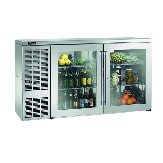
Commercial Back Bar Refrigeration
BBS60
(glass door option shown)
Product Series Covered in this Manual:
Self-Contained
BBS
BBSN
PTS
DZS
SDBS
SDPS
BBSLP
DDC
DDS
Service Manual
Self-Contained and Remote units
using hydrocarbon refrigerant R290
(glass door and solid stainless steel door options shown)
BBR
BBRN
PTR
SDBR
SDPR
BBRLP
download a pdf copy
Remote
Scan here to
of this manual.
BBR96
Form No. Z2606
01.24.2019
Advertisement
Table of Contents

Subscribe to Our Youtube Channel
Related Manuals for Perlick BBR96


Summary of Contents for Perlick BBR96
- Page 1 Service Manual Commercial Back Bar Refrigeration Self-Contained and Remote units using hydrocarbon refrigerant R290 BBS60 (glass door option shown) BBR96 (glass door and solid stainless steel door options shown) Product Series Covered in this Manual: Self-Contained Remote BBSN BBRN SDBR...
- Page 2 Back Bar Operation Installation Manual Table of Contents 1.0 GENERAL INFORMATION ..................Use of Service Manual ..................Model Families ....................2.0 SAFETY INFORMATION ..................Refrigerant HC-R290 ................... Servicing with with HC-R290 ................Service Manual Safety Labels ................3.0 TROUBLESHOOTING GUIDE – REFRIGERATION SYSTEM ......... 4.0 TROUBLESHOOTING GUIDE –...
- Page 3 Back Bar Operation Installation Manual 8.0 SERVICE INSTRUCTIONS - DOORS, DRAWERS, AND SHELVING ...... Proper Door and Drawer Usage ................Reverse Door Swing ..................Replace Door Hinge ................... Sliding Door Models ..................8.4.1 Removing/Installing Sliding Doors ............8.4.2 Adjusting Door Spring Tension ............8.4.3 Torpedo Spring Adjustment ...............
-
Page 4: Table Of Contents
Check for Obstructions .................. Figure 6-9. Fan Mounting Hardware ................Figure 7-1. BBR24, BBRN40 Wiring Diagram ..............Figure 7-2. BBR48, BBR72, BBR96, BBRN60, BBRN80 Wiring Diagram ....... Figure 7-3. BBRLP Wiring Diagram .................. Figure 7-4. BBS/BBSN Wiring Diagram ................Figure 7-5. - Page 5 Back Bar Operation Installation Manual Table of Tables Table 6-1. System Operating Pressures ................Table 6-2. Compressor Data ..................Table 7-1. Electrical Specifications ................. Table 7-2. Load Operation Modes .................. Table 7-3. Controller Where-Used Table ................. Table 7-4. Factory Temperature Settings ................ Table 7-5.
-
Page 6: Figure 1-1. Information Plate For Self-Contained Units
If you have any questions or require additional assistance, contact Perlick Customer Service during regular hours of operation. 1.2 Model Families This manual contains specific instructions for servicing the Perlick Back Bar commercial refrigeration products, which include the following families: SELF-CONTAINED REMOTE BBSN... -
Page 7: Safety Information
Back Bar Operation Installation Manual 2.0 Safety Information 2.1 Refrigerant HC-R290 • The explosion limits are as follows: All self-contained models covered in this service manual are manufactured using refrigerant HC-290 Lower Limit: 1.7% by vol. (37 g/m3) (Propane). Upper Limit: 9.5% by vol. (177 g/m3) 2.2 Servicing with R-290 Ignition Temperature: 470 °C General... - Page 8 Back Bar Operation Installation Manual Return to Table of Contents...
- Page 9 Back Bar Operation Installation Manual Pre-service Safety Check • Ensure the area is free of open flame or burning materials, including cigarettes, candles, or similar It is strongly recommended that all service materials. technicians receive training on the specific • Do not operate appliances that utilize open equipment, procedures, and handling of flammable flames, igniters, or have hot surfaces (for refrigerants before conducting product service. example: electric or gas ranges, electric or gas •...
- Page 10 Back Bar Operation Installation Manual Important Additional Safeguards • If the combustible gas leak detector signals a release of vented refrigerant, the technician If an electrical fault exists that could compromise the should immediately ventilate the room, evacuate refrigerant, repair the electrical fault first. the area, notify the homeowner or customer and wait until the detection device reads a safe level Before performing service, discharge all capacitors in before conducting the following steps.
- Page 11 Back Bar Operation Installation Manual Refrigerant Removal • Compressors may still contain residual refrigerant in the oil after refrigerant is removed. Take these • In all cases, the removal of the refrigerant should precautions: be performed in a well-ventilated area. DO NOT use external heat sources to remove the •...
- Page 12 Back Bar Operation Installation Manual Storage of Flammable Transport of Flammable Refrigerant Cylinders Refrigerant Cylinders • • Ensure that the storage facility has a fire Ensure that a Dry-Powder Fire Extinguisher rated suppression system approved for use with for Class B fires is available on the vehicle. flammable refrigerants. At a minimum, a Dry- • Transport of flammable refrigerant cylinders must Powder Fire Extinguisher rated for Class B fires be in accordance with federal, provincial, state must be located near the storage area and the and local requirements.
- Page 13 Take particular note of the DANGER, WARNING and CAUTION information in this manual. The information is important for the safe and efficient service, operation and care of the Perlick unit. HAZARD!! Indicates hazardous situation that will result in death or serious injury if not avoided.
- Page 14 Use this diagnostic guide to identify issues and to locate applicable instructions within this service manual. This diagnostic guide can be used for any of Perlick’s Back Bar Refrigeration Products. ELECTROCUTION HAZARD!! Never attempt to repair or perform maintenance on the unit until the Main electrical power has been disconnected.
- Page 15 Back Bar Operation Installation Manual PROBLEM CAUSE SOLUTION Probe is not connected to the control. Reconnect probe. See Section 7.5.4. Refrigerator is too warm. Air Infiltration (continued) Sealing compound does not form a Refer to Section 1.1. complete seal. Door gasket is damaged or out of place. Refer to Sections 1.1 and 8.6.
- Page 16 Back Bar Operation Installation Manual PROBLEM CAUSE SOLUTION Condensate pan overflowing. Remove excess water. Check for the following: • Air infiltration. See Section 6.1. • Doors close completely and seals are intact. See Section 8.6. • Ice buildup. See Section 6.5. • Unit is running properly. Repair if needed.
- Page 17 Back Bar Operation Installation Manual 4.0 Troubleshooting Guide – Electrical System Unplugging the condensing unit plug from the molded receptacle shown in the photo IS NOT sufficient to avoid electrical shock hazard. Disconnect power to the main unit by unplugging the main power cord from the wall receptacle or disable power to entire electrical circuit.
- Page 18 Back Bar Operation Installation Manual PROBLEM CAUSE SOLUTION Control not functioning Restore power to unit. No power to unit. Refer to information plate. Section 1.0 Table 7-1 Incorrectly wired harness. Verify wiring per wiring diagram, Section 7.2. Reconnect wires if needed. Replace controller No call for cooling.
- Page 19 Back Bar Operation Installation Manual PROBLEM CAUSE SOLUTION Eliwell Control: LED Coils (continued) Controller display is flashing “AH1” Condensing coil is not clean. Clean with soft brush and vacuum. (continued) Fins are bent or damaged. Straighten fins. Probe Probe is not connected to control. Reconnect probe.
- Page 20 Back Bar Operation Installation Manual PROBLEM CAUSE SOLUTION Dixell Control: LED Power Controller display is Incorrectly wired harness and/or internal Verify wiring per wiring diagram, flashing “HA”. Maximum wiring connections. Section 7.2. Reconnect wires if needed. temperature alarm. Fans (continued) Evaporator fan is not running. Refer to Evaporator fan is not running Coils...
- Page 21 Back Bar Operation Installation Manual 5.0 Troubleshooting Guide – Doors, Drawers and Shelving PROBLEM CAUSE SOLUTION Key won’t come out after Key not in proper position. Rotate key to the proper position and door is locked. remove. Refer to Section 8.4.3.
-
Page 22: Figure 6-1. Sealing Compound At Wiring Pass-Through
Back Bar Operation Installation Manual 6.0 Refrigeration System Repair Instructions 6.1 Air Infiltration STEP 3. Silicone Seal (RTV type) Check for complete silicone seal of: Unplugging the condensing unit plug from • Joint where rear wall meets ceiling the molded receptacle shown in the photo IS NOT sufficient to avoid electrical shock •... -
Page 23: Figure 6-4. Remove Condensing Unit Bracket
Back Bar Operation Installation Manual 6.2 Slide Out the Refrigeration Deck STEP 1. Remove grille by removing 1 Phillips head screw at the top center grille and 2 at the bottom edge. STEP 2. Remove square bracket around the front of condensing unit by removing 6 Phillips screws and 2 hex head bolts. -
Page 24: Table 6-1. System Operating Pressures
Back Bar Operation Installation Manual 6.4 System Operating Pressures 6.4.4 Service Valves Recording Pressure Note: To check operating pressures, you must gain access to the process tubes and install When installing gauges: piercing valves. See Section 6.4.4. 1. Initially purge manifold set with refrigerant type used in unit. -
Page 25: Figure 6-7. Removing Evaporator Fan Panel
Back Bar Operation Installation Manual 6.5 De-Ice Blocked Evaporator Coil – Self-Contained Models STEP 1. STEP 6. Remove shelves and pilaster from refrigerator Reverse steps 1 through 3 to close the evaporator section nearest the evaporator coil. fan panel. STEP 2. 6.6 Air Flow Obstructions Remove Evaporator Fan panel by removing 7 The unit must have free air flow to front grille to... -
Page 26: Ambient Temperature
ELECTROCUTION HAZARD!! Never attempt to repair or perform maintenance on the unit until the Main electrical power has been disconnected. Perlick’s warranty does not cover cleaning of condenser. The condenser is located directly behind the front grille. See Figure 6-4. -
Page 27: Table 6-2. Compressor Data
Back Bar Operation Installation Manual 6.9 Compressors and Condensing Unit Table 6-2. Compressor Data RUN WINDING START WINDING MODEL / RESISTANCE Ω AT RESISTANCE Ω AT 77°F FAMILY WIRING RUN/START 77°F BBS36 1/10 RSCR 7.80 7.10 14.90 BBS60 RSCR 6.72 5.08 11.80 BBS84... -
Page 28: Figure 6-9. Fan Mounting Hardware
Back Bar Operation Installation Manual 6.10 Replace Condenser Fan Motor STEP 1. STEP 2. Remove Refrigeration Deck. See Section 6.2. Cut 2 zip ties holding wire harness to top of the refrigeration module. STEP 2. STEP 3. Unplug the fan power cord from beneath electrical box on compressor. -
Page 29: Leak Detection
Before installing gauges, vent hoses and manifold in Section 6.2. with refrigerant type used in unit. This avoids intro- duction of air into system. Compressor should only be replaced with Perlick OEM parts. Continue to next page… Always replace drier when replacing compressor. - Page 30 Back Bar Operation Installation Manual STEP 4. 6.15 Replace compressor starting device – Self-contained models Install piercing valves on high and low side process tube. STEP 1. Completely slide out refrigeration deck. See NOTE: Never leave piercing valves installed on pro- Section 6.2.
-
Page 31: Table 7-1. Electrical Specifications
Cord Connected DDS84 DDS108 DDC68 DDC92 DZS36 DZS60 PTS36 PTS60 PTS84 SDBS60 SDBS108 SDPS60 BBR24 Remote BBR48 BBR72 BBR96 BBRLP48 BBRLP72 BBRLP96 BBRN40 BBRN60 120 VAC/60 Hz/1 Ph Hard Wired BBRN80 PTR48 PTR72 SDBR48 SDBR96 SDPR48 Return to Table of Contents... -
Page 32: Figure 7-1. Bbr24, Bbrn40 Wiring Diagram
Back Bar Operation Installation Manual 7.2 Wiring Diagrams Figure 7-1. BBR24, BBRN40 Wiring Diagram BBR24/BBRN40 57342A-99-120-RevA Return to Table of Contents... -
Page 33: Figure 7-2. Bbr48, Bbr72, Bbr96, Bbrn60, Bbrn80 Wiring Diagram
Back Bar Operation Installation Manual Figure 7-2. BBR48, BBR72, BBR96, BBRN60, BBRN80 Wiring Diagram BBR48/BBRN60/BBR72/ BBRN80/BBR96 57342A-98-120-RevA Return to Table of Contents... -
Page 34: Figure 7-3. Bbrlp Wiring Diagram
Back Bar Operation Installation Manual Figure 7-3. BBRLP48, BBRLP72, BBRLP96 Wiring Diagram. BBRLP 95322A-120-RevA Return to Table of Contents... -
Page 35: Figure 7-4. Bbs/Bbsn Wiring Diagram
Back Bar Operation Installation Manual Figure 7-4. BBS36, BBS60, BBS84, BBS108, BBSN32, BBSN52, BBSN72, BBSN92 Wiring Diagram BBS/BBSN 57342C-97-120 Return to Table of Contents... -
Page 36: Figure 7-5. Bbslp Wiring Diagram
Back Bar Operation Installation Manual Figure 7-5. BBSLP Wiring Diagram BBSLP 95321C-120 Return to Table of Contents... -
Page 37: Figure 7-6. Dds/Ddc Wiring Diagram
Back Bar Operation Installation Manual Figure 7-6. DDS/DDC Wiring Diagram DDS/DDC 57342C-100-120 Return to Table of Contents... -
Page 38: Figure 7-7. Dzs36 Wiring Diagram
Back Bar Operation Installation Manual Figure 7-7. DZS36 Wiring Diagram DZS36 57342B-108 Return to Table of Contents... -
Page 39: Figure 7-8. Dzs60 Wiring Diagram
Back Bar Operation Installation Manual Figure 7-8. DZS60 Wiring Diagram DZS60 57342B-107 Return to Table of Contents... -
Page 40: Figure 7-9. Ptr Wiring Diagram
Back Bar Operation Installation Manual Figure 7-9. PTR Wiring Diagram 57342A-102-120-RevA Return to Table of Contents... -
Page 41: Figure 7-10. Pts Wiring Diagram
Back Bar Operation Installation Manual Figure 7-10. PTS Wiring Diagram 57342C-101-120 Return to Table of Contents... -
Page 42: Figure 7-11. Sdbr48/Sdbr96 Wiring Diagram
Back Bar Operation Installation Manual Figure 7-11. SDBR48/SDBR96 Wiring Diagram SDBR48-SDBR96 57342A-106-120-RevA Return to Table of Contents... -
Page 43: Figure 7-12. Sdbs Wiring Diagram
Back Bar Operation Installation Manual Figure 7-12. SDBS Wiring Diagram SDBS 57342C-105-120 Return to Table of Contents... -
Page 44: Figure 7-13. Sdpr Wiring Diagram
Back Bar Operation Installation Manual Figure 7-13. SDPR Wiring Diagram SDPR 57342A-104-120-RevA Return to Table of Contents... -
Page 45: Figure 7-14. Sdps Wiring Diagram
Back Bar Operation Installation Manual Figure 7-14. SDPS Wiring Diagram SDPS 57342C-103-120 Return to Table of Contents... -
Page 46: Table 7-2. Load Operation Modes
Back Bar Operation Installation Manual 7.3 Load Operation Modes Table 7-2. Load Operation Modes LOAD COOLING MODE OFF MODE DEFROST MODE Compressor Energized De-Energized De-Energized Condenser Fan Energized De-Energized De-Energized Evaporator Fan Energized Energized Energized Mullion Heaters Energized Energized Energized Eliwell Controller Display No icon illuminated Dixell Controller Display... -
Page 47: Table 7-4. Factory Temperature Settings
7.5.1 Dixell Controller: Reset Factory Parameter press the button for time H02: AP1 label will appear; Settings • Contact Perlick. • Scroll through the various applications (AP1- AP2-AP3) using the keys; 7.5.2 Eliwell Controller: Reset Factory • Select the desired application using the... - Page 48 Back Bar Operation Installation Manual 7.5.3 Replacing Control Module 7.5.3.1 Removing Dixell Controller Tools required STEP 1. Remove the grille by removing 3 Phillips head screws, one at the top center and two at the STEP 4. bottom edge. Cut 2 zip ties holding wire harness to top of the refrigeration module.
- Page 49 Back Bar Operation Installation Manual STEP 9. STEP 6. Remove green probe connector from controller. Disconnect mullion heater wire leads from the main wiring harness. STEP 10. Remove controller assembly from the unit. STEP 7. Disconnect DC driver leads from the main wiring STEP 11.
-
Page 50: Figure 7-15. Attach Probe To Bracket
Back Bar Operation Installation Manual STEP 14. STEP 2. Remove screw holding probe “mass” to the probe Attach probe and mass onto probe bracket with bracket and remove the probe. screw. STEP 3. Use pliers if needed to secure probe notch to sheet metal probe bracket. -
Page 51: Figure 7-16. Temperature Probe And Bracket
Back Bar Operation Installation Manual Temperature Probe 7.5.4 Each refrigerated zone has one 10K TEMPERATURE TEMPERATURE RESISTANCE (°C) (°F) (OHMS) ohm NTC probe, which senses com- partment temperature. Sensing probe 4911 is located behind evaporator fan panel. 4160 3536 To replace temperature probe, refer to Temperature section 7.5.3. -
Page 52: Figure 7-17. Interior Led Light
Back Bar Operation Installation Manual If not within range printed on the part, replace the part. STEP 3. Disconnect DC driver leads from the main wiring harness. Figure 7-17. Interior LED Light 7.7 Replace DC Driver/Inverter STEP 1. Locate DC Driver/Inverter on ceiling of refrigeration compartment. -
Page 53: Figure 8-1. Door Removal
Table 8-1. Door Hinges HINGE KIT - PART NUMBER DESCRIPTION 67439R Right Hinging 67439L Left Hinging Figure 8-1. Door Removal STEP 2. Tools required Pull door to the side and then lower the door. Perlick Hinge Kit Return to Table of Contents... -
Page 54: Figure 8-2. Hinge Removal
Back Bar Operation Installation Manual STEP 3. STEP 5. Remove top and bottom hinge brackets. Retain Using screws removed in step 3, install top and screws for later use. See Figure 8-2. bottom hinge brackets from kit. See Figure 8-3. Figure 8-3. -
Page 55: Figure 8-5. Removing Front Panel
Back Bar Operation Installation Manual STEP 7. STEP 9. Remove front panel from door assembly by Insert V-block into door bottom hinge bracket removing inner mounting screws (4 per side) from and attach with e-clip. See Figure 8-6. Note the perimeter of door assembly. -
Page 56: Figure 8-8. Installing V-Block
Back Bar Operation Installation Manual STEP 11. STEP 13. Place lower V-block into lower cabinet hinge with Insert and tighten lower hinge pin to complete notch parallel to cabinet. See Figure 8-8. assembly. 8.3 Replace Door Hinge See Section 8.2 for hinge replacement instructions. -
Page 57: Figure 8-11. Door Track
Back Bar Operation Installation Manual 8.4.2 Adjusting Door Spring Tension STEP 4. Feed into next notch to tighten/loosen. Tools required STEP 5. Tighten screw. Tension spring is in upper track of each door. 8.5 Drawer & Shelf Slides 8.5.1 Shelving Adjustment Screw Completely empty shelf or drawer before removing. -
Page 58: Figure 8-13. Removing/Installing Drawer
Back Bar Operation Installation Manual 8.5.2 Drawer Divider Adjustment STEP 4. Place drawer on to the extenders, making sure wheels engage the slots on each side. Completely empty shelf or drawer before removing. STEP 5. Push drawer all the way in, then pull drawer out STEP 1. -
Page 59: Figure 8-14. Custom Panel
Back Bar Operation Installation Manual 8.7 Replace Door Handle 8.9 Custom Overlay Panels Tools required Tools required 3/8” Remove front panel from door assembly by STEP 1. removing inner mounting screws (4 per side) Remove door gasket. See Section 8.6. from perimeter of door assembly. -
Page 60: Replacement Parts
Back Bar Operation Installation Manual 9.0 Replacement Parts For parts ordering call (844) 411-8050. 9.1 Refrigeration Module (BBS, BBSN, PTS, SDBS, SDPS, DDS, DDC Model Series) Return to Table of Contents... - Page 61 Back Bar Operation Installation Manual BBS, BBSN, PTS, SDBS, SDPS, DDS, DDC MODELS 3&4- ITEM 1-DOOR 2-DOOR DESCRIPTION DOOR NUMBER QTY. QTY. QTY. Condensing Unit, 1/6 H.P. 115V Condensing Unit, 1/5 H.P., 115V Condensing Unit, 1/4 H.P. 115V Screw, Phillips Truss Head Machine Screw, Thread Cutter, Hex Washer Head Screw, Phillips Truss Head Sheet Metal Screw, Phillips Pan Head Sheet Metal...
- Page 62 Back Bar Operation Installation Manual 9.2 Refrigeration Module (BBSLP Model Series) Return to Table of Contents...
- Page 63 Back Bar Operation Installation Manual BBSLP MODELS 3&4- ITEM 1-DOOR 2-DOOR DESCRIPTION DOOR NUMBER QTY. QTY. QTY. Condensing Unit, 1/6 H.P. 115V Condensing Unit, 1/5 H.P., 115V Condensing Unit, 1/4 H.P. 115V Screw, Phillips Truss Head Machine Screw, Thread Cutter, Hex Washer Head Screw, Phillips Truss Head Sheet Metal Screw, Phillips Pan Head Sheet Metal Screw, Phillips Head...
- Page 64 Back Bar Operation Installation Manual BBSLP MODELS 3&4- ITEM 1-DOOR 2-DOOR DESCRIPTION DOOR NUMBER QTY. QTY. QTY. Bracket, Ratcheting Strain Relief Strain Relief Harness, Fan Motors, Low height Harness, 12VDC Splitter Cover, 60W Driver, Low height Return to Table of Contents...
- Page 65 Back Bar Operation Installation Manual 9.3 Refrigeration Module (DZS Model Series) Return to Table of Contents...
- Page 66 Back Bar Operation Installation Manual DZS MODELS 3&4- 2-DOOR ITEM DESCRIPTION QTY. DOOR QTY. NUMBER QTY. Condensing Unit, 1/6 H.P. 115V Condensing Unit, 1/5 H.P., 115V Screw, Phillips Truss Head Machine Screw, Thread Cutter, Hex Washer Head Screw, Phillips Truss Head Sheet Metal Screw, Phillips Pan Head Sheet Metal Screw, Phillips Head Screw, Sheet Metal...
- Page 67 Back Bar Operation Installation Manual DZS MODELS 3&4- 2-DOOR ITEM DESCRIPTION QTY. DOOR QTY. NUMBER QTY. Strain Relief Nylon, Standoff Controller Board, Damper, Dual Zone Screw, Sheet metal, 6 x 1/2", "a" Relay, Pump Harness Controller Board, Input Damper Control, Red Display Return to Table of Contents...
- Page 68 Back Bar Operation Installation Manual 9.4 Refrigeration Module (DDS-IR Model Series) Return to Table of Contents...
- Page 69 Back Bar Operation Installation Manual DDS-IR MODELS 3&4- 2-DOOR ITEM DESCRIPTION DOOR NUMBER QTY. QTY. Condensing Unit, 1/5 H.P., 115V Condensing Unit, 1/4 H.P. 115V Screw, Phillips Truss Head Machine Screw, Thread Cutter, Hex Washer Head Screw, Phillips Truss Head Sheet Metal Screw, Phillips Pan Head Sheet Metal Screw, Phillips Head Screw, Sheet Metal...
- Page 70 Back Bar Operation Installation Manual 9.5 Fan Motor Assembly Parts (Self-Contained Model Series) SELF-CONTAINED MODELS ITEM DESCRIPTION QTY. NUMBER Motor, Fan Panel, Fan Mounting Panel, Inner Grille Screw, Motor Mounting Screw, Grille Mounting Guard, Product Screw, Guard Mounting Return to Table of Contents...
- Page 71 Back Bar Operation Installation Manual 9.6 Low Profile Evaporator Parts (BBSLP Model Series) LOW PROFILE MODELS ITEM DESCRIPTION QTY. NUMBER Fan, Evaporator Panel, Fan Mounting Screw, Fan Mounting Grille Screw, Grille Mounting Handle, Guard Screw, Guard Handle Mounting Return to Table of Contents...
- Page 72 Back Bar Operation Installation Manual 9.7 Remote Evaporator Parts (BBR, BBRN, PTR, SDBR & BBRLP Model Series) REMOTE MODELS ITEM DESCRIPTION QTY. NUMBER Motor, Fan Panel, Fan Mounting Bracket, Fan Control, Temperature Pan, Evaporator Bushing, 1.75” I.D. Guard, Plastic Fan Return to Table of Contents...
- Page 73 Back Bar Operation Installation Manual REMOTE MODELS ITEM DESCRIPTION QTY. NUMBER Fan Panel, Evaporator (Right) Fan Panel, Evaporator (Left) Plug, Dome Motor, Fan Blade, Fan Evaporator Assembly Coil, 21” Fin Tube, Evaporator Outlet Tube, Evaporator Inlet Clamp, Control Bulb Silicone Return to Table of Contents...
- Page 74 Back Bar Operation Installation Manual NOTES Return to Table of Contents...
- Page 75 Back Bar Operation Installation Manual NOTES Return to Table of Contents...
- Page 76 • • • 8300 West Good Hope Road Milwaukee, WI 53223 • • w Toll Free 800.558.5592 Fax 414.353.7069 ww.perlick.com...
Need help?
Do you have a question about the BBR96 and is the answer not in the manual?
Questions and answers