Table of Contents
Advertisement
Quick Links
User's Manual
PCR-WE Series AC Power Supply
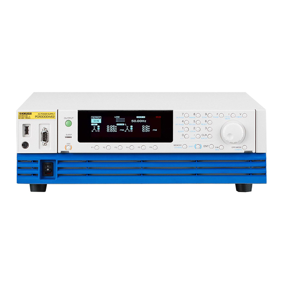
PCR1000WE
PCR2000WE
PCR-WE2 Series AC Power Supply
PCR3000WE2
PCR6000WE2/ PCR6000WE2R
PCR12000WE2/ PCR12000WE2R
PCR18000WE2/ PCR18000WE2R
PCR24000WE2/ PCR24000WE2R
PCR30000WE2/ PCR30000WE2R
PCR36000WE2/ PCR36000WE2R
Part No. IB032791
Sep 2018
Contents 7
Component Names 10
Installation 16
Basic Functions 37
Advanced Functions 84
Sequence Function 111
External Control 150
Parallel Operation 176
System Settings 186
Maintenance 196
Specifications 199
Appendix 220
Advertisement
Table of Contents

Related Manuals for Kikusui PCR-WE series


Summary of Contents for Kikusui PCR-WE series
- Page 1 Part No. IB032791 Sep 2018 User’s Manual Contents 7 Component Names 10 PCR-WE Series AC Power Supply PCR1000WE Installation 16 PCR2000WE Basic Functions 37 PCR-WE2 Series AC Power Supply PCR3000WE2 Advanced Functions 84 PCR6000WE2/ PCR6000WE2R PCR12000WE2/ PCR12000WE2R Sequence Function 111...
-
Page 2: About Manuals
Both unit specifications and manual contents are subject to their instructors. The manuals assume that the reader has change without notice. knowledge about power supplies. © Copyright 2018 Kikusui Electronics Corporation Manual construction • User’s manual (this manual) This document is intended for first-time users of this product. -
Page 3: Notations Used In This Document
Notations Used in This Document Checking the Package Contents • In this manual, the PCR-WE Series AC Power Supply is Check that all accessories are included and that the main also referred to as the “PCR-WE.” The PCR-WE2 Series unit and accessories have not been damaged during trans- AC Power Supply is also referred to as the “PCR-WE2.”... -
Page 4: Safety Precautions
Safety Precautions Moving the Product When installing this product, be sure to observe the pre- When moving or transporting this product to the installation cautions provided in the Safety information manual. location, be sure to observe the “Precautions When Choosing the Installation Location” in the Safety informa- tion manual. -
Page 5: Product Overview
The PCR-WE2 consists of three power modules. Product Overview Model 1P out- 1P3W / 3P output U phase V phase W phase PCR-WE/PCR-WE2 lineup PCR3000WE2 3 kVA 1 kVA 1 kVA 1 kVA PCR6000WE2 6 kVA 2 kVA 2 kVA 2 kVA Model Rated output... - Page 6 USB, LAN, and RS232C interfaces. If an system simulator, you do not need a regenerative load. optional interface board is used, the PCR-WE Series This helps to suppress the level of exhaust heat and can be controlled remotely through a GPIB interface.
-
Page 7: Table Of Contents
Contents About Manuals ...........2 Displaying single-phase three-wire output and three- phase output (PCR-WE2 only) ......42 Notations Used in This Document ......3 Specifying values ..........44 Checking the Package Contents ......3 Adjusting the screen brightness ......45 Safety Precautions ..........4 Viewing the firmware version ....... - Page 8 Wiring the hard sensing and soft sensing functions .. Switching steps at specific phase angles....136 Suddenly changing the phase......139 Wiring the regulation adjustment function .....91 Single-phase three-wire output and three-phase out- Compensation function setup procedure ....92 put basics............141 Ending the use of the compensation function ..95 Phase setting for multi-phase output ....142 Phase sweep ............146 Using Power Line Abnormality Simulations..
- Page 9 Updating ............195 GPIB interface board (IB07-PCR-WE) ....232 Base hold angles (OP03-KRC) ......233 Parallel operation cables (PC01-PCR-WE, LC01- PCR-LE) ............. 233 Maintenance Troubleshooting ..........234 Alarms and Trouble ........237 Cleaning the Dust Filter ........196 Overview ............237 Backup Battery Replacement ......198 Remedy ..............
-
Page 10: Component Names
Component Names Front panel PCR1000WE PCR2000WE PCR3000WE2 PCR6000WE2 PCR12000WE2 PCR18000WE2 PCR24000WE2 PCR30000WE2 PCR36000WE2 (PCR6000WE2 example) Name Function USB port (host) Connects to an external keyboard. Saves to setup memory. p.79 Used for updating. p.195 REMOTE connector Connector for the optional line impedance network or dip simulator. RS232C port RS232C port for remote control. - Page 11 Control panel 15 16 Name Function OUTPUT Turn the output on and off. p.56 Display Displays the settings, measured values, and other information. p.61 Numeric keypad Enters values directly. p.44 CLR key Clears the input entered with the numeric keypad. ON PHASE key Sets the output-on phase.
- Page 12 Display and Icons LOAD RESP.M OUTPUT 99.00 6.87 28.1 RANGE Freq 50.00Hz FREQ FMAX FMIN Name Function Status, measured-value, and setting dis- Displays the product’s present status, measured values, and p.39 play area settings. Entry area Area for entering various values and system settings. Function key name area Displays the present functions above the function keys (F1 to F6).
- Page 13 icons Description LAN status, red: not connected, orange: connecting, green: communication possible, — blinking: identify status Load level meter p.63 Output-off phase setting p.59 Output-on phase setting p.59 Output on p.56 Output off p.56 “OFF” blinks when soft stop is in use. p.105 Output off, voltage surge suppression function on p.58...
- Page 14 Rear Panel PCR1000WE/ PCR2000WE/ PCR3000WE2 (PCR1000WE example) PCR6000WE2/ PCR12000WE2 (PCR6000WE2 example) User’s Manual PCR-WE/PCR-WE2...
- Page 15 PCR18000WE2/ PCR24000WE2/ PCR30000WE2/ PCR36000WE2 (PCR30000WE2 example) Name Function AC INPUT terminal block Power inlet with a cover. p.16 OUTPUT terminal block Output terminal block with a cover p.27 ANALOG IN connector Analog control connector p.151 DIGITAL I/O connector Digital control connector. p.161 USB port (device) USB port for remote control.
-
Page 16: Installation
Installation Connecting the Power Cord This product is designed as an equipment of IEC Overvoltage Category II (energy-consuming equipment supplied from a fixed installation). Risk of electric shock. WARNING • This product is IEC Safety Class I equipment (equipment with a protective conductor terminal). - Page 17 Installation | Connecting the Power Cord If you will not use one of the optional input power cords, prepare a power cord that meets the following specifications. Cable Nominal cross- Maximum input Input terminal current sectional area PCR1000WE Single-phase Single core, 3 pcs. 5.5 mm or more 17 A 200 V input PCR2000WE...
- Page 18 Installation | Connecting the Power Cord Switchboard breaker requirements • Rated current: The circuit breaker of which the rated current is more than the following current is disabled for safety. PCR1000WE:30 A (100 V system, 15 A (200 V system) PCR2000WE: 50 A (100 V system), 30 A (200 V system) PCR3000WE2: 75 A (100 V system), 40 A (200 V system) PCR6000WE2: 50 A (three-phase three-wire input model), 30 A (three-phase four-wire input model)
-
Page 19: Connecting The Pcr1000We/Pcr2000We/Pcr3000We2
Installation | Connecting the Power Cord Connecting the PCR1000WE/PCR2000WE/PCR3000WE2 Turn off the switchboard’s circuit breaker. Check that the AC power line meets the nominal input rating of the product. Acceptable input voltage (any nominal supply voltage in the following ranges): Single-phase 100 V input: 100 Vac to 120 Vac Single-phase 200 V input: 200 Vac to 240 Vac Frequency: 50 Hz or 60 Hz... - Page 20 Installation | Connecting the Power Cord Connecting the PCR6000WE2/PCR12000WE2 Check that the AC power line meets the nominal input rating of the product. Acceptable input voltage (any nominal supply voltage in the following ranges): Three-phase 200 V input: 200 Vac to 240 Vac (line voltage) Three-phase 400 V input: 380 Vac to 480 Vac (phase voltage) Frequency: 50 Hz or 60 Hz Turn the POWER switch off ( ).
- Page 21 Installation | Connecting the Power Cord Unfasten the two M4 screws from the bottom terminal block cover, and remove the cover. Bottom terminal block cover Change the direction of the bottom terminal block cover, and attach it. This will keep the crimping terminals from being exposed. Bottom terminal block cover Turn off the switchboard’s circuit breaker.
-
Page 22: Connecting The Pcr18000We2/Pcr24000We2/ Pcr30000We2/Pcr36000We2
Installation | Connecting the Power Cord Connecting the PCR18000WE2/PCR24000WE2/ PCR30000WE2/PCR36000WE2 Check that the AC power line meets the nominal input rating of the product. Acceptable input voltage (any nominal supply voltage in the following ranges): Three-phase 200 V input: 200 Vac to 240 Vac (line voltage) Three-phase 400 V input: 380 Vac to 480 Vac (phase voltage) Frequency: 50 Hz or 60 Hz Turn the POWER switch off ( ). - Page 23 Installation | Connecting the Power Cord Connect the power cord according to the indication on the switchboard. For the three-phase 200 V input model (excluding the PCR36000WE2), remove the two M3 screws, change the orientation of the INPUT terminal cover, and fasten with the screws you just removed.
-
Page 24: Turning The Power On
Installation Turning the Power On When you turn on the POWER switch for the first time after purchase, do it without any load connected in order to check the status of the product. Preventing the shutdown function from activating Connect the included external control (DIGITAL I/O) connector to the DIGITAL I/O connector to release the shutdown function (p.165 p.169... -
Page 25: Turning The Power Switch On
Installation | Turning the Power On Turning the POWER switch on Check that nothing is connected to the OUTPUT terminal block on the rear panel. Check that the power cord is connected correctly. Check whether the supplied external control connector is connected to the DIGITAL I/O connector on the rear panel. -
Page 26: Setting The Condition That The Product Will Be In When The Power Switch Is Turned On
Installation | Turning the Power On Setting the condition that the product will be in when the POWER switch is turned on In the factory default condition, when you turn the POWER switch on, the product starts in the same state as it was in the last time it was turned off (the output set to off). -
Page 27: Connecting The Load
Installation Connecting the Load The maximum current that this product can generate varies depending on the model. It also varies depending on the output voltage and frequency. Ensure that the output power capacity is sufficient for the load capacity. The maximum output currents (for rms output voltage of 1 V to 100 V or 2 V to 200 V and frequency greater than 40 Hz or DC) for the different models are shown in the following table. -
Page 28: Connecting To The Output Terminal Block
Installation | Connecting the Load Connecting to the OUTPUT terminal block We recommend that you run the load wires alongside each other and tie them together at several points with cable ties. Connect between the output terminal and load with the shortest wires possible. Preparing wires Use noncombustible wires that have diameters that correspond to the output current to connect to the load. -
Page 29: Connecting The Pcr1000We/Pcr2000We
Installation | Connecting the Load Connecting the PCR1000WE/PCR2000WE Turn the POWER switch off ( ). Turn off the switchboard’s circuit breaker. Unfasten the two M3 screws from the OUTPUT terminal cover, and remove the cover. Securely connect the load cables to the OUTPUT terminal block. If the load has a ground (GND) terminal, be sure to connect it to the (ground) terminal of the product’s OUTPUT terminal block. -
Page 30: Connecting The Pcr3000We2
Installation | Connecting the Load Connecting the PCR3000WE2 For single-phase output Risk of electric shock. Be sure to connect the three N cables. There is a risk of WARNING touching the unused terminals through the gap of the OUTPUT terminal cover. Turn the POWER switch off ( ). - Page 31 Installation | Connecting the Load For three-phase output and single-phase three-wire output Turn the POWER switch off ( ). Turn off the switchboard’s circuit breaker. Unfasten the two M3 screws from the OUTPUT terminal cover, and remove the cover. If a short bar is attached across the U, V, and W terminals, remove it. Remove Securely connect the load cables to the OUTPUT terminal block.
- Page 32 OUTPUT terminal block. Be sure to use a wire whose diameter is greater than or equal to the diameter of the wires used to connect the load. For single-phase output, if you are using a bus bar or the like to make the connection, contact your Kikusui agent or distributor. Three-phase output...
- Page 33 Installation | Connecting the Load Adjust the OUTPUT terminal cover so that the unused terminals are not exposed. Single-phase three-wire output Three-phase output Single-phase output Fasten the terminal cover you removed in step 3 with the three screws. Example of single-phase User’s Manual PCR-WE/PCR-WE2...
-
Page 34: Connecting The Pcr18000We2/Pcr24000We2/ Pcr30000We2/Pcr36000We2
Installation | Connecting the Load Connecting the PCR18000WE2/PCR24000WE2/ PCR30000WE2/PCR36000WE2 Risk of electric shock. WARNING • Attach the OUTPUT terminal cover so that the terminals are not exposed according to the output system. • To use single-phase output, be sure to connect three cables each for L and N. There is a risk of touching the unused terminals through the gap of the OUTPUT terminal cover. - Page 35 OUTPUT terminal block. Be sure to use a wire whose diameter is greater than or equal to the diameter of the wires used to connect the load. For single-phase output, if you are using a bus bar or the like to make the connection, contact your Kikusui agent or distributor. Three-phase output...
- Page 36 Installation | Connecting the Load To use three-phase output or single-phase three-wire output, attach the OUTPUT (N) terminal cover so that the unused terminals are not exposed. Single-phase three-wire output Three-phase output This completes the connections. User’s Manual PCR-WE/PCR-WE2...
-
Page 37: Basic Functions
Basic Functions Panel Operation Basics This section explains the status indicators of the product and the basic operation of the product from the front panel. Control panel You can pull out the control panel and tilt it to one of the two available settings. You cannot detach the control panel from the PCR1000WE/PCR2000WE/PCR3000WE2 because the tilt angle is fixed. - Page 38 Basic Functions | Panel Operation Basics Attaching the control panel The control panel detachment buttons are not used when you attach the control panel to the PCR-WE. Simply press on the control panel until you hear a click. • Factory default Align the upper groove and the lower groove on the control panel with the upper pin and lower pin on the PCR-WE, respectively, and then push the control panel back into the PCR-WE.
-
Page 39: Parts Of The Screen
Basic Functions | Panel Operation Basics Parts of the screen The screen consists of the following three parts. LOAD RESP.M OUTPUT 99.00 Status, measured-value, and setting display area 6.87 28.1 RANGE Freq 50.00Hz Entry area FREQ FMAX FMIN Function key name area ... -
Page 40: Explanation Of Function Keys In This Manual
Basic Functions | Panel Operation Basics Explanation of function keys in this manual The function keys in this manual are explained in a tabular form as shown below. Item Title Description Conditions that are not allowed The item name that is The title that is An explanation of When the PCR-WE is being used... -
Page 41: Busy Status
Basic Functions | Panel Operation Basics Busy status Busy status refers to the condition in which the product’s output cannot be turned on or it’s settings cannot be changed because of the ongoing hardware or firmware process. When the product is in the busy status, “Busy...”... -
Page 42: Displaying Single-Phase Three-Wire Output And Three-Phase Output (Pcr-We2 Only)
Basic Functions | Panel Operation Basics Displaying single-phase three-wire output and three-phase output (PCR-WE2 only) Changing the phase display You can display all phases or only a single phase. All-phase Single-phase display (example of U-phase display) Press PHASE (SHIFT+F) to set the phase to display. Parameter Title Description... - Page 43 Basic Functions | Panel Operation Basics Phase voltage and line voltage In three-phase AC output, when the phase difference between U, V, and W is 120° and the output voltages are equal, Line voltage = √ 3 × phase-voltage Phase voltage = line voltage / √ 3 Phase voltage Line voltage Specifying unbalance...
-
Page 44: Specifying Values
Basic Functions | Panel Operation Basics Specifying values To specify values, use the numeric keypad or the rotary knob. When the cursor is displayed in the entry area, you can use the numeric keypad or the rotary knob to specify a value. Numeric keypad operations If you use the numeric keypad to enter a value, the value that you entered is displayed in the entry area. -
Page 45: Adjusting The Screen Brightness
Basic Functions | Panel Operation Basics Digit function The digit function enables you to use the rotary knob to change only the specified digit and the higher digits when you are setting the voltage or frequency. This function is useful when you are changing the voltage or frequency in steps. -
Page 46: Viewing The Firmware Version
Basic Functions | Panel Operation Basics Viewing the firmware version To view the product’s firmware version, press CONFIG (SHIFT+OPR MODE) > MODEL ID (F5). When parallel operation is in use, the model information of the slave unit is also displayed. When an option board is installed, its information is also displayed. -
Page 47: Selecting The Output Method
Basic Functions Selecting the Output Method Select the output method (single-phase output, single-phase three-wire output, or three-phase output). (PCR-WE2 only) Current will not flow through unused terminals. The OUTPUT terminal connection needs to be changed according to the output method setting. When making a change, be sure to turn off the POWER switch. -
Page 48: Setting The Output Voltage
Basic Functions Setting the Output Voltage Set the output voltage range and output voltage. Setting the output voltage range This product has the following output voltage ranges: L and H. (The factory default setting is L.) Output voltage range setup procedure When you select the L range, RANGE OUTPUT... -
Page 49: About Setting The Output Voltage
Basic Functions | Setting the Output Voltage About setting the output voltage You can set the output voltage regardless of whether the output is on or off. The measured value is always displayed. Set the voltage limit to prevent the product from generating a voltage that is greater than is necessary (p.67). - Page 50 Basic Functions | Setting the Output Voltage When the output is on If the output is on, the measured value and the setting are displayed. You can adjust the output voltage while viewing the output voltage setting and the measured value. If you are using the rotary knob to set the value, you may increase or decrease the value too much because the display response is slow.
-
Page 51: Output Voltage Setup Procedure For Single-Phase Output
Basic Functions | Setting the Output Voltage Output voltage setup procedure for single-phase output Press V > ACVOLT (F1) to set the AC voltage. Press V > DCVOLT (F2) to set the DC voltage. The DC voltage can be set only when the peak value of the AC+DC waveform is between -445.5 V and 445.5 V for the H range or -222.8 V and 222.8 V for the L range. - Page 52 Basic Functions | Setting the Output Voltage Setting the DC voltage Specifying the output voltage with phase voltages Press V > DC PH VOLT (F3) to set the DC voltage to assign to the U phase. The V phase is automatically set to the same amplitude as the U phase but with reverse polarity.
-
Page 53: Output Voltage Setup Procedure For Three-Phase Output
Basic Functions | Setting the Output Voltage Output voltage setup procedure for three-phase output Setting the AC voltage Specifying the output voltage with phase voltages To set all the phases at the same time, press V > AC PH VOLT (F1). To set the U phase, press V >... -
Page 54: Setting The Voltage Offset
Basic Functions | Setting the Output Voltage Setting the DC voltage To set all the phases at the same time, press V > DC PH VOLT (F3). To set the U phase, press V > 1/4 (F6) > 2/4 (F6) > U DCVOLT (F1). To set the V phase, press V > 1/4 (F6) >... -
Page 55: Setting The Frequency
Basic Functions Setting the Frequency You can set the frequency regardless of whether the output is on or off. Set the frequency limit to prevent the product from generating a frequency that is greater than is necessary (p.68). On the 500 Hz limit model, the upper limit is limited to 500 Hz only for three-phase output. ... -
Page 56: Turning The Output On/Off
Basic Functions Turning the Output On/Off Risk of electric shock. WARNING Do not touch the OUTPUT terminal block or the sensing terminals. If a capacitor, battery, or similar item is connected as the load, a voltage remains until the load’s energy is discharged, even when the output is off. Do not touch parts that are connected to the OUTPUT terminal block or sensing terminals. -
Page 57: Impedance When The Output Is Off
Basic Functions | Turning the Output On/Off Impedance when the output is off The internal circuits and the output of the PCR-WE are not separated by a mechanical switch or relay. The PCR-WE turns the output off by electrically increasing the output impedance. This enables you to turn the output on and off without chattering. -
Page 58: Voltage Surge Suppression When The Output Is Turned Off
Basic Functions | Turning the Output On/Off Voltage surge suppression when the output is turned off You can set the voltage surge suppression that is activated when the output is turned off. When the output is off, the output of this product is at high impedance. If voltage surge suppression is set to ON (factory default setting), immediately after the output is turned off, the output voltage is set to 0 V (low output impedance), and then the impedance is changed to high. -
Page 59: Output On/Off Phase Control
Basic Functions | Turning the Output On/Off Output on/off phase control You can set the output-on phase and output-off phase separately for AC output. For single-phase three-wire output and three-phase output, set the U-phase. Output on Output off Output-on phase setup procedure When you are controlling the output-on phase, set the phase angle as well. -
Page 60: Ac Coupling
Basic Functions | Turning the Output On/Off AC coupling This product uses an internal DC amplifier to achieve the functions of DC output and power line abnormality simulation. The AC signal (AC REF) generated internally is input directly into the DC amplifier. The product can reliably amplify the power of the AC REF signal and output the signal, but the DC voltage component included in the AC REF signal is also amplified and output (a DC offset voltage is superimposed on the AC output voltage). -
Page 61: Measurement Display
Basic Functions Measurement Display You can monitor the present output value. When the output is off, this is nearly 0. You can change the phase to display for single-phase three-wire output and three-phase output. (p.42) Displaying the voltage The measured voltage is displayed in the status, measured-value, and setting display area. You can select whether to display the rms, peak, or average voltage. - Page 62 Basic Functions | Measurement Display Holding the peak voltage If the measurement display is set to peak voltage, the peak voltage can be held. Press V-MEAS (SHIFT+V) > 1/2 (F6) > VPK TIM (F5) to set the hold time. Parameter Title Description Factory default...
-
Page 63: Load Level Meter
Basic Functions | Measurement Display Load level meter The load level meter displays the ratio of the output current (which is detected as the current flowing through the load) to the rated current on a bar graph. This can be used to determine the approximate output current supply capability. -
Page 64: Displaying The Current, Power, And Power Factor
Basic Functions | Measurement Display Displaying the current, power, and power factor You can select which value to display normally in the status, measured-value, and setting display area from rms current, peak current, average current, power, apparent power, and power factor. To switch the display, press I/P/S/λ-MEAS (SHIFT+I) to select the item that you want to display. - Page 65 Basic Functions | Measurement Display Holding the peak current The peak current is displayed as an absolute value of the maximum instantaneous current measured. Even if a negative DC voltage is being generated, the peak current is displayed as a positive value. If the measurement display is set to peak current, the peak current can be held.
-
Page 66: Limit Function And Protection Function
Basic Functions Limit Function and Protection Function This product has the following limit functions and protection functions. • Limit function Limits can be placed on the PCR-WE output voltage setting and frequency setting. They prevent damage to the load caused by mistaken operations and limit the current that flows through the load. •... -
Page 67: Setting Limits
Basic Functions Setting Limits Limits can be placed on the PCR-WE output voltage setting and frequency setting. They prevent damage to the load caused by mistaken operations and limit the current that flows through the load. You can set limits in advance according to the load conditions. You can set limits regardless of whether the output is on or off. -
Page 68: Upper And Lower Frequency Limits
Basic Functions | Setting Limits Upper and lower frequency limits Limits can be placed on the product’s output frequency. They prevent damage to the load caused by mistaken operations. You can set limits in advance according to the load conditions. After you set the frequency limits, you will no longer be able to specify frequency values that are outside of the range that you have set. - Page 69 Basic Functions | Setting Limits • Positive peak current limit and negative peak current limit You can set positive and negative peak current limits. This function instantly limits the peak output current. When the current is being limited by the peak current limit, “IPK.LIM” is displayed. Setting the peak current limits does not change the load level meter's full scale.
- Page 70 Basic Functions | Setting Limits Action that is performed when the current limit is exceeded You can set the action to perform (whether the output is turned off) when the current exceeds the current limit. You can set the amount of time that must elapse before the output is turned off when the current limit is exceeded.
- Page 71 Basic Functions | Setting Limits If ENABLE (turn off the output) is selected To clear the alarm, press ALM CLR (SHIFT+CLR). Risk of malfunction. If an overload occurs, be sure to remove the cause of the problem, and CAUTION then press OUTPUT.
-
Page 72: Using Protection Functions
If an alarm still occurs even after you have corrected all the causes of alarms, the product may be malfunctioning. Stop using it immediately, and contact your Kikusui agent or distributor. Tell the agent or distributor the displayed alarm number. - Page 73 Basic Functions | Using Protection Functions Overload protection If the output current exceeds the rated current or the current limit (and the action to perform when the limit is exceed is set to turn off the output) (p.70), the overload protection is activated, and an alarm (ALM-06: OVERLOAD) is generated.
-
Page 74: Using The Memory
Basic Functions Using the Memory The product’s settings can be saved to memory (internal memory or USB memory device). Items that can be saved Internal memory The product has a preset memory and setup memory. • Preset memory The following items can be saved to the internal preset memory (A, B, C). Because you can easily recall saved settings, this feature is useful when you want to switch between three different settings (sudden voltage change or sudden frequency change). -
Page 75: Using Internal Preset Memory
Basic Functions | Using the Memory Using internal preset memory The frequency, AC voltage, DC voltage, and waveform bank number can be stored to and recalled from the internal preset memory (up to three sets in A, B, and C). This is useful when you are testing drastic changes in voltage or frequency. - Page 76 Basic Functions | Using the Memory Recalling from preset memory Recalling is not possible in the following situations. The settings to be recalled are outside the range of the present limit function or protection function. The output voltage range is L, and the voltage setting to be recalled exceeds the L range. The peak value of the AC+DC waveform is outside the output voltage range.
-
Page 77: Setting The Date And Time (Time Zone)
Basic Functions | Using the Memory Setting the date and time (time zone) The date and time are used to assign the time of creation of the files saved to the setup memory or USB memory device. If you change the time zone, the year, month, and day change accordingly. If the product is connected to LAN and can access the Internet, the year, month, and day will be updated automatically when you set the time zone. -
Page 78: Using The Internal Setup Memory
Basic Functions | Using the Memory Using the internal setup memory Up to 10 sets of panel settings can be saved to the internal setup memory and recalled. (p.191) Saving or recalling is not possible when the output is on or while power line abnormality simulation or sequences are running. -
Page 79: Using A Usb Memory Device
Basic Functions | Using the Memory Using a USB memory device The following items can be saved to a USB memory device. Panel settings (items that can be saved to the setup memory) Power line abnormality simulation settings Sequence data Selected waveform bank data All items that can be saved (present output method, panel settings, power line abnormality simulation settings, sequence data, all waveform bank data) - Page 80 Basic Functions | Using the Memory Folders where the files are saved and file names The following folders are created in the root folder of the USB memory device, and the data is saved. You cannot delete or rename folders from the product. Use a PC to perform these operations. Use alphanumeric characters for the folder names.
- Page 81 Basic Functions | Using the Memory Saving to a USB memory device Set the date and time before saving to the a USB memory device (p.77). Set up the configuration you want to save. Connect a USB memory device to the USB port on the front panel. Press OTHERS (SHIFT+MEMORY) >...
- Page 82 Basic Functions | Using the Memory Recalling panel settings, power line abnormality simulation, or sequence data from a USB memory device Connect a USB memory device to the USB port on the front panel. Press OTHERS (SHIFT+MEMORY) > 1/2 (F6) > FILE (F5) > LOAD (F1). Select the item that you want to recall.
- Page 83 Basic Functions | Using the Memory Recalling waveform bank data or all contents that can be saved Connect a USB memory device to the USB port on the front panel. Press OTHERS (SHIFT+MEMORY) > 1/2 (F6) > FILE (F5) > LOAD (F1). Select the item that you want to recall.
-
Page 84: Advanced Functions
Advanced Functions Using the Sync Function The sync function synchronizes the frequency and phase of the product’s output voltage to a 50 Hz or 60 Hz input power supply or external sync input signal (EXT SYNCHRO). This is useful in situations such as when the display of an external measuring instrument is not stable. To finely control the synchronization phase of the input voltage on three-phase input models, set the synchronization delay phase angle. - Page 85 Advanced Functions | Using the Sync Function Turning the sync function on and off If the input voltage frequency is outside of the rated range or if the input power supply voltage distortion and the noise are extremely large, synchronization is not possible. SYNC NG or EXT SYNC NG will be displayed.
-
Page 86: Using The Compensation (Voltage Compensation) Function
Advanced Functions Using the Compensation (Voltage compensation) Function The compensation function compensates for voltage drops in the load cables when the load is connected to the product over a long distance. This product has three types of compensation functions: hard sensing, soft sensing, and regulation adjustment. - Page 87 Advanced Functions | Using the Compensation (Voltage compensation) Function • Regulation adjustment This function calculates the voltage drops that are caused by the output current and increases the output voltage just by the calculated voltage drops. Use this function when there is a great distance between the PCR-WE and the load and you want to stabilize the voltage across the load.
-
Page 88: Wiring The Hard Sensing And Soft Sensing Functions
Advanced Functions | Using the Compensation (Voltage compensation) Function Wiring the hard sensing and soft sensing functions We recommend that you run the load wires alongside each other and tie them together at several points with cable ties. Connect between the output terminal and load with the shortest wires possible. Hard sensing can compensate up to approximately 1.5 V for a single line. - Page 89 Advanced Functions | Using the Compensation (Voltage compensation) Function Turn the POWER switch off. Turn off the load’s power switch. If the load’s power switch cannot be turned off, provide a dedicated terminal block for sensing. Do not connect the load to the dedicated terminal block for sensing. Connect the cables by referring to the following sensing wiring diagrams.
- Page 90 Advanced Functions | Using the Compensation (Voltage compensation) Function Use the included cable tie to gently tie the cables as shown below. The cable tie can be reused. Do not cut the extraneous portion of the tie. Sensing cables You can pull out the band by holding here with a pair of tweezers.
-
Page 91: Wiring The Regulation Adjustment Function
Advanced Functions | Using the Compensation (Voltage compensation) Function Checking the sensing cables When you are using the hard sensing function or soft sensing function, after you finish wiring the sensing cables, check that there are no wiring errors. Turn the load's power switch off before you perform this check. -
Page 92: Compensation Function Setup Procedure
Advanced Functions | Using the Compensation (Voltage compensation) Function Compensation function setup procedure Set the voltage and the frequency that you want to stabilize at the sensing point. For DC output, set only the voltage. The hard sensing function is used. Hard sensing cannot be used if the output impedance is turned on. - Page 93 Advanced Functions | Using the Compensation (Voltage compensation) Function The soft sensing function is used. Soft sensing cannot be set in the following situations. Output impedance is turned on. The action to perform when the current limit is exceeded is set to DISABLE. Soft start and soft stop are on.
- Page 94 Advanced Functions | Using the Compensation (Voltage compensation) Function The regulation adjustment function is used. Regulation adjustment is not possible in the following situations. Output impedance is turned on. The action to perform when the current limit is exceeded is set to DISABLE. A waveform bank number other than zero is specified.
-
Page 95: Ending The Use Of The Compensation Function
Advanced Functions | Using the Compensation (Voltage compensation) Function Ending the use of the compensation function Press OTHER (SHIFT+MEMORY) > 1/2 (F6) > COMPEN (F2) > OFF (F1) to end the use of the compensation function. User’s Manual PCR-WE/PCR-WE2... -
Page 96: Using Power Line Abnormality Simulations
Advanced Functions Using Power Line Abnormality Simulations You can simulate power supply line errors by stopping the PCR-WE output (to simulate power failures) and decreasing and increasing the voltage (to simulate voltage dips and pops). You can use this to test switching power supplies and other electronic devices. Power outage Voltage drop (dip) Voltage increase (pop) - Page 97 Advanced Functions | Using Power Line Abnormality Simulations Voltage regulation start polarity You can set the zero crossing (the time at which the voltage becomes zero) that will be the reference for T1 to positive zero crossing or negative zero crossing by switching the voltage regulation start polarity (POL).
-
Page 98: Power Line Abnormality Simulation Setup Procedure
Advanced Functions | Using Power Line Abnormality Simulations Power line abnormality simulation setup procedure You cannot set limits when the sync function is on. You can set this function regardless of whether the output is on or off. Set the steady-state voltage and frequency. Press SIM >... -
Page 99: Executing And Stopping Power Line Abnormality Simulations
Advanced Functions | Using Power Line Abnormality Simulations Executing and stopping power line abnormality simulations You cannot execute power line abnormality simulation in the following situations. • The action to perform when the current limit is exceeded is set to DISABLE. •... -
Page 100: Using The Harmonic Analysis Function
You can perform harmonic analysis on the output voltage and output current. A simplified measurement method is used, so this method does not conform to standards such as IEC. For standard-compliant measurements, use the Kikusui Harmonic/Flicker Analyzer KHA3000. The analyzed harmonic varies depending on the output frequency. -
Page 101: Generating Special Waveforms (Waveform Bank)
Advanced Functions Generating Special Waveforms (Waveform bank) Peak clipped waveforms and flat curve waveforms can be output. You can use remote control to configure user-defined waveforms. For details, see the Communication Interface Manual on the included CD-R. This product creates reference waveforms for output voltage by performing D/A conversion on the data that is stored in its internal memory. -
Page 102: Setting The Waveform Bank
Advanced Functions | Generating Special Waveforms (Waveform bank) Setting the waveform bank You cannot set the waveform bank when the sync function is running or when the external analog input function (EXTDC, VPROG) is in use. The PCR-WE cannot use waveforms created with the PCR-LE. Press OTHERS (SHIFT+MEMORY) >... -
Page 103: Generating Special Waveforms
Advanced Functions | Generating Special Waveforms (Waveform bank) Generating special waveforms You can generate special waveforms regardless of whether the output is on or off. When you set the compensation function to regulation adjustment or soft sensing, you cannot change the waveform bank number while the soft start is being performed, soft stop is being performed, or when the product is being controlled with an external analog signal and the signal source is set to external signal (EXT) only. -
Page 104: Setting The Output Impedance
If you require official IEC standard test data, use the Kikusui Line Impedance Network (LIN Series). The output impedance can be turned on only when the compensation function is off. -
Page 105: Configuring Soft Start And Soft Stop
Advanced Functions Configuring Soft Start and Soft Stop The output voltage can be gradually increased when the output is turned on to control the load device’s inrush current (soft start). The output voltage can be gradually decreased when the output is turned off to control the inductive kickback that occurs when the current is cut off (soft stop). -
Page 106: Configuring Soft Stop
Advanced Functions | Configuring Soft Start and Soft Stop Configuring soft stop Press OTHERS (SHIFT+MEMORY) > 1/2 (F6) > FALL TIM (F1) to configure soft stop. If you select ON, “FALL TIM” will be displayed. Parameter Title Description Conditions that are not allowed ON (F2) Fall Time Sets the fall time (0.1 s to 3.0 s) -
Page 107: Selecting The Response
Advanced Functions Selecting the Response You can set the response speed of the internal amplifier (to one of the following three levels) according to the load conditions and how you will use the PCR-WE. You can prevent the output from becoming unstable or from oscillating depending on the load circuits (especially in the case of capacitive loads) and the wiring conditions. -
Page 108: Using The Power Management Functions
Advanced Functions Using the Power Management Functions The PCR-WE has the following two power management functions: a sleep function and a power-saving function Sleep function You can set the PCR-WE so that it enters sleep mode after a certain amount of time passes with its power on but no output being generated (the output is off). -
Page 109: Power-Saving Function
Advanced Functions | Using the Power Management Functions Power-saving function This product consists of power modules that cover the rated output capacity. If you are using the product at less than the rated output capacity, the product can operate using only the necessary power modules. -
Page 110: Power Module Management Function
Advanced Functions | Using the Power Management Functions Power module management function This product consists of power modules that cover the rated output capacity. If you do not want to use a failed power module, you can specify the module by module ID and pause it. You can view failed power modules by pressing ALM CHK (F5) when an alarm (ALM-08-01) is activated. -
Page 111: Sequence Function
Sequence Function Sequence Overview A sequence is a series of settings—values such as the output voltage, frequency, and time—that are saved in advance and are then recalled and automatically carried out in order at a later time. Sequences are groups of executable units called steps. When a sequence is executed (run), its steps are executed in order, starting with the specified starting step. - Page 112 Sequence Function | Sequence Overview When a sequence is completed, the product’s settings are those of the last step. If the output is on in the last step of the sequence, the output will remain on when the sequence is completed. The step editing screen is shown on page 8 (page 9 for single-phase three-wire output and three-phase output).
- Page 113 Sequence Function | Sequence Overview Step’s signal change (ramp) To change (sweep) the frequency or voltage linearly over the specified time, select “RAMP ON.” To change the value as a step, select "RAMP OFF." If you specify "RAMP ON" in step 0, the signal will change linearly from the current voltage or frequency. FREQ When the ramp is off When the ramp is on...
- Page 114 Sequence Function | Sequence Overview Starting phase angle and ending phase angle Steps are managed in terms of time. If you set the starting phase angle, steps will start from the specified phase angle. Phase wait time is the duration from the point when the step time of the last step has elapsed to the point where the phase angle reaches the starting phase angle.
- Page 115 Sequence Function | Sequence Overview Display and signal output during the phase wait time During the phase wait time, the screen shows the next step number. The elapsed time remains at zero until the next step starts. The status signal is output while the waveform of the step that is enabled is being output. Step n-1 Step n Panel display...
-
Page 116: Editing Steps
Sequence Function Editing Steps The step editing screen is shown on page 7 (page 9 for single-phase three-wire output and three-phase output). Press SEQ (SHIFT+SIM) > EDIT (F5) to display the step editing screen. You cannot edit steps when the sync function is on. Common items The step or parameter that you are configuring is indicated with a different background color. -
Page 117: Frequency And Ac Voltage
Sequence Function | Editing Steps [1] Frequency and AC voltage Use this screen to set the frequency and the AC voltage. The step signal change can also be set for the frequency and the AC voltage. If the peak AC+DC output voltage exceeds the product’s rated output voltage, the output voltage waveform (the peak section) may be distorted (clipped). -
Page 118: Execution Time, Waveform Bank
Sequence Function | Editing Steps [2] Execution time, waveform bank Use this screen to set the step execution time, the waveform bank, and the output. If you are setting the waveform bank to use for each phase for three-phase output, press WB NO (F3) to first set all the phases at the same time, and then press V WB NO (F4) or W WB NO (F5) to set the V phase and W phase, respectively. -
Page 119: Dc Voltage, Output
Sequence Function | Editing Steps [3] DC voltage, output Use this screen to set the DC voltage. The step signal change can also be set for the DC voltage. If the peak AC+DC output voltage exceeds the product’s rated output voltage, the output voltage waveform (the peak section) may be distorted (clipped). -
Page 120: Status Output, Trigger Output, Trigger Input (Pause)
Sequence Function | Editing Steps [4] Status output, trigger output, trigger input (pause) Risk of electric shock. Use the DIGITAL I/O connector with an isolation voltage of WARNING 42 Vpeak or less. Use this screen to set the status signal output, trigger signal output, and trigger signal input wait. Set the signal polarity with the external control function. - Page 121 Sequence Function | Editing Steps Step n-1 Step n Panel display The sequence pauses until a trigger signal is received. Step n-1 Step n Trigger input Step n: ON Trigger signal input Status signal Step n: ON Status signal Step n-1: ON Step n: ON User’s Manual PCR-WE/PCR-WE2...
-
Page 122: Jump Function
Sequence Function | Editing Steps [5] Jump function Use this screen to set whether to skip over steps or repeat steps. Parameter Title Description TYPE(F2) NORM(F4) Step Type After this step is completed, the subsequent step will be executed. JUMP(F5) After this step is completed, the specified step will be executed. -
Page 123: Starting Phase Angle, Ending Phase Angle, Sudden Phase Change
Sequence Function | Editing Steps [6] Starting phase angle, ending phase angle, sudden phase change Use this screen to set the starting phase angle, ending phase angle, and sudden phase change. Parameter Title Description S.PHASE(F2) FREE(F5) Start Phase Does not set the starting phase angle FIXED(F4) Sets the starting phase angle (0.0 deg to 360.0 deg, 0=360) E.PHASE(F3) -
Page 124: Output Impedance (For Single-Phase Output)
Sequence Function | Editing Steps [7] Output impedance (for single-phase output) Use this screen to set the output impedance. Parameter Title Description OUT IMP.(F2) OFF(F4) Out Z Disables the output impedance ON(F5) Enables the output impedance RESIST(F3) Resistance Sets the output impedance (resistance component). REACT(F4) Reactive Sets the output impedance (reactance component). -
Page 125: Phase Difference For Three-Phase Output
Sequence Function | Editing Steps [9] Phase difference for three-phase output Use this screen to set the U-phase offset phase angle and the phase differences of the V phase and W phase relative to the U phase. Also set the step’s signal change. Set this when only one or two phases are to change suddenly or when performing a phase sweep. - Page 126 Sequence Function | Editing Steps U phase offset setting. If you set the U phase offset, the U phase will be offset from the reference phase. As a result, the U-V/U-W phase difference settings will be offset from the actual phase difference. Offset phase Reference phase Phase difference...
-
Page 127: Setting Sequence Conditions
Sequence Function Setting Sequence Conditions The items that you set here are shared between all steps. Setting the starting step number and the ending step number On the sequence screen, press COND (F4) to set the starting step number and the ending step number (starting step number <... -
Page 128: Executing, Pausing, And Stopping Sequences
Sequence Function Executing, Pausing, and Stopping Sequences After you have finished setting the steps and the sequence conditions, you can execute the sequence. Press SEQ (SHIFT + SIM) > RUN (F1) to run the sequence. You cannot run a sequence in the following situations. •... -
Page 129: Sequence Creation Tutorial
Sequence Function Sequence Creation Tutorial The following information will be explained. • Sequence creation basics (p.131) Describes basic sequence settings (voltage, frequency, and ramp). • Voltage sweep and frequency sweep (p.134) Describes how to sweep a waveform using the ramp function. •... - Page 130 Sequence Function | Sequence Creation Tutorial • Phase sweep (p.146) Describes how to set a sequence so that the phase is swept for multi-phase output. • Line voltage dip (p.148) Describes how to set a line voltage dip. User’s Manual PCR-WE/PCR-WE2...
-
Page 131: Sequence Creation Basics
Sequence Function | Sequence Creation Tutorial Sequence creation basics This section explains how to use a sequence to output the following waveform. STEP Steps ACVOLT [V] 10.0 10.0 AC voltage RAMP Voltage ramp (ACVOLT) FREQ [Hz] 50.0 50.0 50.0 50.0 50.0 50.0 40.0... - Page 132 Sequence Function | Sequence Creation Tutorial The default frequency is 50.0 Hz. Press ▲ repeatedly until you reach the frequency of step 006. (If steps 001 to 005 are not set to 50.0 Hz, start by setting the frequencies from step 001.) Then, use the rotary knob to specify 40.0 Hz.
- Page 133 Sequence Function | Sequence Creation Tutorial • There is a step where the trigger wait setting (TRIG.IN) and the sudden phase change setting (PHAS.CHG) are both turned on. • The output impedance setting is out of range. • The external analog input function (VPROG) is in use. •...
-
Page 134: Voltage Sweep And Frequency Sweep
Sequence Function | Sequence Creation Tutorial Voltage sweep and frequency sweep This section describes a sequence for outputting a continuous waveform that linearly changes from 0 V to 10 V. STEP000 STEP001 STEP003 STEP005 STEP007 STEP008 STEP002 STEP004 STEP006 Step ACVOLT [V] AC voltage 10.0 10.0... - Page 135 Sequence Function | Sequence Creation Tutorial For the procedure to set steps on this product, see “Sequence creation basics” (p.131). Likewise, frequency sweeps also need starting frequency steps. STEP001 STEP003 STEP005 STEP006 STEP000 STEP002 STEP004 Step ACVOLT [V] AC voltage 10.0 10.0 10.0...
-
Page 136: Switching Steps At Specific Phase Angles
Sequence Function | Sequence Creation Tutorial Switching steps at specific phase angles This section explains how to switch steps at specific phase angles to produce a continuous waveform. Steps are managed in terms of time. If the starting phase angle and ending phase angle are set to FREE (default setting), the next step will start when the step time elapses. - Page 137 Sequence Function | Sequence Creation Tutorial The phase angle of step 001 when its step time elapses is 90°. Because the starting phase angle of step 002 is 0°, the PCR-WE waits until the phase angle of step 001 becomes 0° before executing step 002. This duration is the phase wait time.
- Page 138 Sequence Function | Sequence Creation Tutorial In this example, the starting phase angle of step 001 is FREE, so there is no phase wait time. Theoretically, there should not be any phase wait time if the starting phase angle is set to 0°, but depending on the conditions, the waveform may be offset by on period.
-
Page 139: Suddenly Changing The Phase
Sequence Function | Sequence Creation Tutorial Suddenly changing the phase To suddenly change the phase, specify a sudden phase change after setting the starting and ending phase angles. This section explains an example of how to suddenly change the phase from 90° to 270° when the step changes from 002 to 003. - Page 140 Sequence Function | Sequence Creation Tutorial To use sudden phase change, be sure to set the ending phase angle of the previous step and the starting phase angle of the step in which you want the phase to suddenly change. If you specify sudden phase change with either phase angle set to FREE, the phase will not change with the correct angles.
-
Page 141: Single-Phase Three-Wire Output And Three-Phase Output Basics
Sequence Function | Sequence Creation Tutorial Single-phase three-wire output and three-phase output basics Single-phase three-wire output In single-phase three-wire output, the V-phase waveform is an inverted waveform of the U phase. U phase V phase Three-phase output The figure below shows the output of a three-step sequence where the U-V phase difference is 120° and the U-W phase difference is 240°... -
Page 142: Phase Setting For Multi-Phase Output
Sequence Function | Sequence Creation Tutorial Phase setting for multi-phase output This section explains how to set phase angles for multi-phase output. For details on the operation of starting and ending phase angles, see “Switching steps at specific phase angles” (p.136). For details on the operation of sudden phase changes, see “Suddenly changing the phase”... - Page 143 Sequence Function | Sequence Creation Tutorial Next, we will explain how to set the steps so that only the U phase suddenly changes. In the example below, the U phase is suddenly changed from 0° to 30° when step 001 begins. The waveforms of the V and W phases are continuous.
- Page 144 Sequence Function | Sequence Creation Tutorial Lastly, we will explain how to set the steps so that the V and W phases suddenly change. To suddenly change the V phase, set the U-V phase difference. To suddenly change the W phase, set the U-W phase difference.
- Page 145 Sequence Function | Sequence Creation Tutorial The example below shows a sudden phase change in which step 001 begins at 0° when step 000 ends with the V phase at 90°. The waveforms of the U and W phases are continuous. Because the U-V phase difference is 120°, the V phase is 90°...
-
Page 146: Phase Sweep
Sequence Function | Sequence Creation Tutorial Phase sweep First, we will explain the phase sweeping of the U phase. To sweep the U phase, you have to set the U phase offset. When a U phase offset is specified, the U-V phase difference, U-W phase difference, starting phase angle, and ending phase angle settings are relative to the U phase reference phase. - Page 147 Sequence Function | Sequence Creation Tutorial Below is an example of sweeping the V phase and an example of sweeping the U and V phases. Phase sweeping only the V phase Phase sweeping the U and V phases Reference phase Offset phase Reference phase Phase difference...
-
Page 148: Line Voltage Dip
Sequence Function | Sequence Creation Tutorial Line voltage dip The following example shows how to set line voltage dips (short two phases: 70% residual voltage). 116.6 V 91.6 V 10° UVW phase 116.6 V U phase voltage W phase voltage 91.6 V Step 000 Step 001... - Page 149 Sequence Function | Sequence Creation Tutorial We set the U and W phase voltages to 116.6 V and the voltage ramp to on. To sweep the U phase clockwise to 0°, we set the U phase (U phase offset) to 0° and set the ramp to LAG. To sweep the W phase counterclockwise to 240°, we set the W phase (U-W phase difference) to 240°...
-
Page 150: External Control
External Control The PCR-WE can be controlled and monitored from an external device. Control Functions that can be controlled/monitored Connector Analog control Amplify the input waveform ANALOG IN Change the voltage or frequency Digital control Control using external contacts DIGITAL I/O Monitor operating status ... -
Page 151: Control Using Analog Signals
External Control Control Using Analog Signals External analog signals can be used to perform the following controls. • Amplify the input waveform Input Output AC 220 Vrms Ex.: 1 VACrms Sine Sine GAIN x220 • Change the AC voltage, DC voltage, or frequency to output using a DC signal Input Sine Output... -
Page 152: Analog In Connector Pin Arrangement
External Control | Control Using Analog Signals ANALOG IN connector pin arrangement PCR1000WE PCR2000WE Manufacturer address: 1-1-3, Higashiyamata, Tsuzuki-ku, Yokohama, 224-0023, Japan PCR3000WE2 D-sub 9-pin (female) ANALOG IN WEIGHT OUTPUT 1-155V/2-310V ∼ 1.4-219V/2.8-438V connector pin SENSING D-sub 9-pin (female) PCR6000WE2 ANALOG IN PCR12000WE2... -
Page 153: Selecting The Parameter To Control
External Control | Control Using Analog Signals Selecting the parameter to control Press OTHERS (SHIFT+MEMORY) > EXT ANLG (F4) > INPUT (F1) to set the parameter to control with the external analog signal. Parameter Title Description OFF(F1) EXT Signal Disables the use of the external analog signal EXTDC(F2) Amplifies the input waveform VPROG(F3) -
Page 154: Amplifying The Input Waveform (Extdc Mode)
External Control | Control Using Analog Signals Amplifying the input waveform (EXTDC mode) You can use the PCR-WE as a power amplifier that simply amplifies the input waveform or use it to add an external signal to the PCR-WE signal source. For single-phase output and single-phase three-wire output, Ch. - Page 155 External Control | Control Using Analog Signals Setting the measurement time If the measurement time is not set, the voltage and current that are being output may be different from what are displayed on the panel. With a longer measurement time, the measurements become more stable, but it takes longer to update the display of the measured values.
- Page 156 External Control | Control Using Analog Signals Adjusting the gain You can set the gain between x5 to x220. If you want to output 150 Vac (L range), apply 1.5 Vac to the ANALOG IN connector, and set the gain around x100.
-
Page 157: Varying The Output Voltage Or Frequency Using Dc Signals (Vprog Mode)
External Control | Control Using Analog Signals Varying the output voltage or frequency using DC signals (VPROG mode) The following parameters can be varied using DC signals. • AC voltage In response to the external DC signal (0 Vdc to 10 Vdc) input, 0 Vac to 155 Vac (for L range) or 0 Vac to 310 Vac (for H range) is output. - Page 158 External Control | Control Using Analog Signals Selecting the controlled parameter for three-phase output Press OTHERS (SHIFT+MEMORY) > EXT ANLG (F4) > INPUT (F1) > EDIT (F5) > VPROG (F3) > MAP (F1) to select the channel configuration. Parameter Title Description ALL(F1) VProgram map Ch A: AC voltage, Ch B: DC voltage, Ch C: Frequency...
- Page 159 External Control | Control Using Analog Signals Finely adjusting the offset and gain You can finely adjust the voltage offset and gain. This is not applied to the frequency. Adjusting the offset You can adjust the offset. With the ANALOG IN connector shorted, adjust the offset so that the output voltage is as close to 0 Vdc as possible.
- Page 160 External Control | Control Using Analog Signals Limit function If an external signal is used, you will not be able to use the following functions. Soft start Power line abnormality simulations Sequence function Harmonic analysis function User’s Manual PCR-WE/PCR-WE2...
-
Page 161: Control Using Digital Signals
External Control Control Using Digital Signals External degital signals can be used to perform the following controls. • Controlling the PCR-WE through external contacts • Monitoring the operation status User’s Manual PCR-WE/PCR-WE2... -
Page 162: Digital I/O Connector Pin Arrangement And Mapping
External Control | Control Using Digital Signals DIGITAL I/O connector pin arrangement and mapping There are four channels (CTRL.1 to CTRL.4) that are controlled using external contacts, four channels (STAT.1 to STAT.4) that monitor the operating status, and two channels (DIO.1, DIO.2) that you can select whether to control using external contacts or monitor the operating status (Selectable I/O). - Page 163 External Control | Control Using Digital Signals Control signals that can be mapped to the pins The signals to be controlled can be mapped to the channels of the DIGITAL I/O connector. The following table shows the signals that can be mapped. CTRL.4 and STAT.4 cannot be mapped. For details, see “Controlling the PCR-WE through external contacts”...
- Page 164 External Control | Control Using Digital Signals Controlling with external contacts using CTRL channels To reduce the influence of noise on the output, connect a 2-core shielded wire or a twisted-pair wire, and keep the wire as short as possible. If the wiring is long, it becomes easy for noise to influence the operation of the PCR-WE.
-
Page 165: Controlling The Pcr-We Through External Contacts
External Control | Control Using Digital Signals Controlling the PCR-WE through external contacts There are four channels (CTRL.1 to CTRL.4) that can be controlled through external contacts. For CTRL.1 to CTRL.3, you can select (map) control signals. CTRL.4 is fixed to shutdown signal. There are two additional channels (DIO.1, DIO.2) that you can select whether to control using external contacts or monitor the operating status (p.173). - Page 166 External Control | Control Using Digital Signals Press CONFIG (SHIFT+OPR MODE) > EXT.DIO (F2) > CTRL.IN (F1). Select the channel (CTRL.1(F1)/ CTRL.2(F2)/ CTRL.3(F3)) you want to assign the parameter to. CTRL.4 is fixed (shutdown). You cannot set this value. Press ENABLE (F1) to enable external contact control on the assigned channel. If you want to disable it, press DISABLE (F2).
- Page 167 External Control | Control Using Digital Signals Turning output on and off (Output Control) If two or more units are floating, and you are using a single external contact to turn output on and off for all the units, use a relay or similar device for the external contact signal to isolate the signal transmitted to each unit.
- Page 168 External Control | Control Using Digital Signals External alarm input (External Alarm) Alarms can be generated through external contacts. “ALM-19 EXT ALARM” is displayed, and the output turns off. Changing the output method (Wiring Control) The output method can be changed through external contacts (excluding the PCR1000WE and PCR2000WE).
- Page 169 External Control | Control Using Digital Signals Shutdown CTRL.4 is used for shutdown. The output can be turned off by force through external contacts. This takes precedence over the feature that turns the output on and off through external contacts. The power module operation is also stopped. The logical polarity is fixed (positive).
-
Page 170: Monitoring The Operation Status
External Control | Control Using Digital Signals Monitoring the operation status You can externally monitor the following operation status of the product. There are four channels for monitoring (STAT.1 to STAT.4). For STAT.1 to STAT.3, you can select (map) control signals. STAT.4 is fixed to alarm status. There are two additional channels (DIO.1, DIO.2) that you can select whether to control using external contacts or monitor the operating status (p.173). - Page 171 External Control | Control Using Digital Signals Press CONFIG (SHIFT+OPR MODE) > EXT.DIO (F2) > STAT.OUT (F2). Select the channel (STAT.1(F1)/ STAT.2(F2)/ STAT.3(F3)) you want to assign the parameter to. STAT.4 is fixed (alarm status). You cannot set this value. Press ENABLE (F1) to enable monitoring on the assigned channel.
- Page 172 External Control | Control Using Digital Signals Output method status (Wiring Status, excluding the PCR1000WE and PCR2000WE) When you use two channels, you can check the output method. Wiring 1P Status is set to on for single-phase output. Wiring 1P3W Status is set to on for single-phase three-wire output. Wiring 3P Status is set to on for three-phase output.
-
Page 173: Selectable I/O
External Control | Control Using Digital Signals Selectable I/O There are two selectable I/O channels (DIO.1, DIO.2) that you can select whether to control using external contacts or monitor the operating status . You can select (map) control signals. When using external contacts for control, the same control signal cannot be assigned to multiple channels (CTRL.1 to CTRL.4, DIO.1, DIO.2). - Page 174 External Control | Control Using Digital Signals Press CONFIG (SHIFT+OPR MODE) > EXT.DIO (F2) > SEL DIO (F3). Select the channel (DIO.1(F1)/ DIO.2(F2)) you want to assign the parameter to. If you want to control through external contacts press INP.SIG (F1). If you want to monitor the operating status, press OUTP.SIG (F2).
-
Page 175: Selectable Signals When Inp.sig Is Selected
External Control | Control Using Digital Signals Selectable signals when INP.SIG is selected For details on topics other than the output reference phase input, sequence trigger input, and programmable signal in, see “Control Using Digital Signals” (p.161). Output reference phase signal (Sync Clock In) Apply a signal when you want to synchronize the sync function with an external signal. -
Page 176: Parallel Operation
Parallel Operation This product is capable of master-slave parallel operation, which allows all slave units to be controlled by a master unit (excluding the PCR1000WE, PCR2000WE, and PCR3000WE2, up to four units). If the input wiring system is the same, parallel operation is possible even among models with different power capaci- ties. -
Page 177: Configuring The Master And Slave Units
Parallel Operation Configuring the Master and Slave Units In parallel operation, the master unit controls all slave units. The master unit’s panel shows the measurements, and the slave units’ panels show their slave unit num- bers. PARALLEL Align the arrow to SLAVE the number you want to assign. -
Page 178: Installation And Connection
Parallel Operation Installation and Connection Installation Use the master unit to control all the slave units. It is convenient to place the master unit in an easy-to- operate location. Using the optional parallel operation connection cable (PC01-PCR-WE), connect the PCR-WEs. Arrange the PCR-WEs so that they are as close to each other as possible (so that tension is not applied to the con- necting cables). - Page 179 Parallel Operation | Installation and Connection Turn the POWER switch off. Securely connect the master unit’s PARALLEL OUT connector to the slave unit’s PARALLEL IN connector using a parallel operation connection cable. To perform parallel operation with three or more units, connect all PARALLEL connectors using connection cables in the same manner.
- Page 180 Parallel Operation | Installation and Connection Connection and configuration for synchronizing the power supply To synchronize the power supply, the optional power synchronize cable (LC01-PCR-LE) is required. You can configure the system so that when you turn on the master unit, all the slaves also turn on. Remove the terminal covers.
- Page 181 Parallel Operation | Installation and Connection Set the master unit’s POWER SELECTOR switch to MASTER. The POWER SELECTOR switch is on the front panel. Set the all slave units’ POWER SELECTOR switches to SLAVE. Turn on all slave units’ POWER switches. This completes power synchronize cable connections.
-
Page 182: Turning The Power On And Checking The Operation
Parallel Operation Turning the Power On and Checking the Operation Parallel operation is controlled from the master unit. The master unit displays the total output current of the system. Connecting the OUTPUT terminal block and relay terminals Refer to the following figure, and connect the OUTPUT terminal block and relay terminals. For details on connecting the load, see chapter 1. -
Page 183: Turning The Power On
Parallel Operation | Turning the Power On and Checking the Operation Turning the power on Power on If power supply syncing is enabled, turn on the master unit’s POWER switch. If power supply syncing is disabled, turn on the POWER switches on the master unit and all slave units within 10 seconds. -
Page 184: Connecting The Load
Parallel Operation Connecting the Load Connect the relay terminals and the load. Risk of electric shock. WARNING • Before you connect cables, be sure to turn the POWER switch off, and then remove the power plug from the outlet or turn off the switchboard. •... -
Page 185: Ending Parallel Operation
Parallel Operation Ending parallel operation To end parallel operation, turn off the power, and then remove the connection cables from the PARALLEL connectors and the power synchronize cables from the J1 and J2 connectors. Hold down the lock lever of the power synchronize cable, and pull it free of the unit. -
Page 186: System Settings
System Settings Setting the Watchdog Protection (WDP) This function turns off PCR-WE output when SCPI communication is not performed for a length of time that is equal to or exceeds the WDP setting. Press CONFIG (SHIFT+OPR MODE) > COM-I/F (F1) > 1/2 (F6) > WT DOG (F1) to set the watchdog pro- tection. -
Page 187: Displaying/Changing The Interface Settings
System Settings Displaying/Changing the Interface Settings For details on connections and configuration, see the Communication Interface Manual (in the included CD-ROM). Controlling the PCR-WE/WE2 from a PC You can control the PCR-WE/WE2 from a PC by using the Web browser interface. To use the Web browser interface, you need to connect the PCR-WE/WE2 to a PC through a LAN. -
Page 188: Displaying Scpi Errors
System Settings Displaying SCPI Errors You can check the content of the SCPI error when an SCPI error occurs during remote control. Up to 16 errors are displayed. If the 17th error occurs, the 16th error changes to “-350 Queue overflow,” and subsequent errors are not displayed. -
Page 189: Factory Default Settings And Reset Settings
System Settings Factory Default Settings and Reset Settings On this product, you can return all the settings to their factory default conditions or return just a portion of the settings to their factory default conditions. • Returning all settings to their factory defaults (sanitize) Press CONFIG (SHIFT+OPR MODE) >... -
Page 190: Factory Default Settings
System Settings | Factory Default Settings and Reset Settings Factory default settings system settings Settings are not returned to their factory default conditions even when the product is reset. The settings apply to all output methods. Parameter Factory default Three-phase output Output method Key lock... - Page 191 System Settings | Factory Default Settings and Reset Settings Panel settings Settings are returned to their factory default conditions even when the product is reset. There is a separate setting for each output method. Parameter Factory default 1000WE 2000WE 3000WE2 6000WE2 12000WE2...
- Page 192 System Settings | Factory Default Settings and Reset Settings Parameter Factory default 1000WE 2000WE 3000WE2 6000WE2 12000WE2 18000WE2 24000WE2 30000WE2 36000WE2 Panel display Phase — — All (Phase voltage display) Voltage Rms voltage Current, Rms current power, power factor Peak voltage hold time Peak current hold time Measurement Voltage...
- Page 193 System Settings | Factory Default Settings and Reset Settings Waveform bank Settings are not returned to their factory default conditions even when the product is reset. The settings apply to all output methods. Parameter Factory default Waveform type Sine User-defined waveform (set only from remote control) Sine Crest factor...
- Page 194 System Settings | Factory Default Settings and Reset Settings Sequence function Settings are not returned to their factory default conditions even when the product is reset. There is a sep- arate setting for each output method. • Sequence condition settings Parameter Factory default Starting step number...
-
Page 195: Updating
Updating You can update the PCR-WE firmware by using a USB memory device. If there is an update, you can obtain it from the download service on the Kikusui website (http://www.kiku- sui.co.jp/en/download/). Save the update files (Update.img, CHECKSUM.md5) in the root directory of the USB mem- ory device. -
Page 196: Cleaning The Dust Filter
Maintenance Cleaning the Dust Filter A dust filter is installed on the inside of the louver on the front panel. Periodically clean the filter to prevent clogging. • If the dust filter is clogged, the product’s internal cooling capabilities will be reduced. This may lead to malfunction or the reduction of the product's service life. - Page 197 Maintenance | Cleaning the Dust Filter Clean the dust filter. Use a vacuum cleaner to dispose of the dust and foreign particles that are attached to the dust fil- ter. If the filter is extremely dirty, clean it using water-diluted neutral detergent, and dry it com- pletely.
-
Page 198: Backup Battery Replacement
When the battery is exhausted, the time becomes inaccurate. For information about replacing the battery, contact your Kikusui agent or distributor. Calibration The product is calibrated before shipment. To maintain long-term performance, we recommend periodic calibration. To have your product calibrated, contact your Kikusui agent or distributor. User’s Manual PCR-WE/PCR-WE2... -
Page 199: Specifications
Specifications Main Unit Specifications Unless specified otherwise, the specifications are for the following settings and conditions. • The warm-up time is 30 minutes (with current flowing). • TYP: These are typical values that are representative of situations where the product operates in an environment with an ambient temperature of 23 °C. -
Page 200: Input (Ac Rms)
Specifications Input (AC rms) Single-phase output Single-phase/three-phase switchable model 1000WE 2000WE 3000WE2 6000WE2 12000WE2 18000WE2 24000WE2 30000WE2 36000WE2 Voltage 1P2W input 100 Vrms to 120 Vrms, — model (nominal) 200 Vrms to 240 Vrms 3P3W input — 200 Vrms to 240 Vrms (3 phase line voltage) model 3P4W input —... - Page 201 Specifications Regeneration function The models in the following table have a regeneration function. 6000WE2R 12000WE2R 18000WE2R 24000WE2R 30000WE2R 36000WE2R 6 kVA 12 kVA 18 kVA 24 kVA 30 kVA 36 kVA Maximum regenerated power Maximum reverse 1P2W 60 A/ 30 A 120 A/ 60 A 180 A/ 90 A 240 A/ 120 A 300 A/ 150 A 360 A/ 180 A power flow current...
-
Page 202: Output
Specifications Output Single-phase output Single-phase/three-phase switchable model 1000WE 2000WE 3000WE2 6000WE2 12000WE2 18000WE2 24000WE2 30000WE2 36000WE2 4 times the maximum output current Maximum peak current Current at 3 times the maximum Current at 1.4 times the maximum output current for 0.5 s Inrush current capacity output current for 0.07 s 82 % (TYP) -
Page 203: Output Voltage Stability (Phase Voltage)
Specifications DC voltage Single-phase output Single-phase/three-phase switchable model 1000WE 2000WE 3000WE2 6000WE2 12000WE2 18000WE2 24000WE2 30000WE2 36000WE2 DC voltage Rating -219 V to +219 V, -438 V to +438 V -222.5 V to +222.5 V, -445.0 V to +445.0 V Setting range Resolution 0.1 V... -
Page 204: Measurement
Specifications Measurement Single-phase output Single-phase/three-phase switchable model 1000WE 2000WE 3000WE2 6000WE2 12000WE2 18000WE2 24000WE2 30000WE2 36000WE2 Voltage Resolution 0.1 V Rms value DC, 40 Hz to 999.9 Hz: ±(0.3 % of reading +1 V) Accuracy 1 kHz to 5 kHz: ±(0.5 % of reading +1 V) Current Resolution 0.01 A... -
Page 205: Limit Values And Protection Functions
Specifications Limit values and protection functions Setting range Resolution Voltage Upper AC voltage limit 0.0 V to 315.0 V 0.1 V protection Lower AC voltage limit Upper DC voltage limit -445.5 V to 445.5 V 0.1 V Lower DC voltage limit Output overvoltage Rms value 14.0 V to 489.5 V... -
Page 206: Power Line Abnormality Simulations
Specifications Power line abnormality simulations Setting range Resolution Setting accuracy 0 deg to 359.9 deg 0.1 deg ±1 deg (≤1 kHz) TIME 0.0 ms to 999.9 ms 0.1 ms ±(1×10 +0.1 ms) 0 ms to 99990 ms 1 ms ±(1×10 +0.1 ms) 0.1 ms to 9999.0 ms 0.1 ms... -
Page 207: Output Impedance Setting
Specifications Output impedance setting Single-phase output Single-phase/three-phase switchable model 1000WE 2000WE 3000WE2 6000WE2 12000WE2 18000WE2 24000WE2 30000WE2 36000WE2 Resistance 0 Ω to 0 Ω to 0 Ω to 0 Ω to 0 Ω to 0 Ω to 0 Ω to 0 Ω... -
Page 208: Communication Interface
Specifications Communication interface Software protocol IEEE Std 488.2-1992 Command language Complies with SCPI Specification 1999.0 Complies with the USB 2.0 specifications; data rate: 480 Mbps (high speed), socket B type, self-powered Message terminator LF or EOM during reception, LF + EOM during transmission Device class Complies with the USBTMC-USB488 device class specifications IEEE802.3, 100Base-TX Ethernet... -
Page 209: Signal I/O
Specifications Signal I/O Insulation resistance Between primary and 500 Vdc, 10 MΩ or more terminals Between secondary and 500 Vdc, 10 MΩ or more terminals Between input and output Non-isolated (shared common circuit) terminals Withstanding voltage Between primary and t 1.5 kVac for 1 minute erminals Between secondary and... - Page 210 Specifications Digital I/O (DIGITAL IO connector) Terminal DSUB 9-pin connector (female), #4-40 inch screws Digital input (CTRL.1 to CTRL.4) Number of channels 4ch (1ch is fixed input) Input The maximum open-circuit voltage across input pins is approximately 12 V, and the maximum short-circuit current is approximately 6.4 mA. The internal circuit is pulled up to 12 V by a 1.7 kΩ...
- Page 211 Specifications Digital output (STAT.1 to STAT.4) Number of channels 4ch (1ch is fixed output) Output Photocoupler open collector output (30 Vdc, 8 mAmax) Selectable DISABLE No enabled functions output signals Output ON Status Output on status I Pk Limit Status Peak current limit status Overload Status Overload status...
- Page 212 Specifications Selectable I/O (DIO.1 to DIO.2) Number of channels Input L level input voltage 0 V to 0.8 V H level input voltage 2 V to 5 V Output L level output voltage 0 V to 0.55 V H level output voltage 3.8 V to 5 V Maximum low-level sink 12 mA...
-
Page 213: Parallel Operation (Pcr1000We/ Pcr2000We/ Pcr3000We2 Excluded)
Specifications Parallel operation (PCR1000WE/ PCR2000WE/ PCR3000WE2 excluded) Maximum number of units in parallel operation N: (number of units in parallel operation) ≤ 4 [Capacity of 1 PCR-WE]×N I/O power (current) capacity Output voltage Load regulation ≤ ±0.5 V stability With respect to 0 % to 100 % variation in the rating Variation according to output frequency ≤... -
Page 214: Response Selection Function
Specifications Response selection function High-speed response (FAST) mode Normal response (MED) mode High stability response (SLOW) mode Ecological function Sleep function Power-saving function Power module management function Soft start and soft stop functions Soft start Rise time setting range: 0.1 to 30 s Soft stop Fall time setting range: 0.1 to 3 s LIN, DSI connection I/O... -
Page 215: General
Specifications General Single-phase output Single-phase/three-phase switchable model 1000WE 2000WE 3000WE2 6000WE2 12000WE2 18000WE2 24000WE2 30000WE2 36000WE2 Insulation Between input and 500 Vdc, 10 MΩ or more resistance chassis, output and chassis, and input and out- Withstand- Between input and 1.5 kVac, 2.15 kVdc for 1 minute ing voltage chassis, output and chassis,... -
Page 216: Rated Output Current Characteristics (Derating)
Specifications Rated output current characteristics (derating) The rated output current depends on the output conditions (output voltage, output frequency). The rated output current under given output conditions is the value obtained by converting the smaller of the two val- ues: the output current ratio derived from fig. 1 (output voltage) or the output current ratio derived from fig. 2 (output frequency). -
Page 217: Outline Drawing
Specifications Outline Drawing Unit: mm (inches) PCR1000WE/ PCR2000WE/ PCR3000WE2 MAX20 (0.79) 655 (25.79) MAX710 (27.95) PCR6000WE2 MAX20 (0.79) 550 (21.65) MAX620 (24.41) User’s Manual PCR-WE/PCR-WE2... - Page 218 Specifications PCR12000WE2 MAX20 (0.79) 550 (21.65) MAX620 (24.41) PCR18000WE2/ PCR24000WE2 MAX20 (0.79) 550 (21.65) MAX660 (25.98) User’s Manual PCR-WE/PCR-WE2...
- Page 219 Specifications PCR30000WE2/ PCR36000WE2 550 (21.65) MAX20 (0.79) MAX660 (25.98) User’s Manual PCR-WE/PCR-WE2...
-
Page 220: Appendix
Appendix Terminology Rated output capacity The maximum output power capacity (in VA) that can be supplied continuously. For example, this is 6 kVA on the PCR6000WE2. Rated output current The maximum rms current (in A) that can be output continuously. The rated output current varies depending on the output conditions (the number of power modules in use, output voltage range, output voltage, output frequency). - Page 221 Appendix | Terminology Output voltage waveform distortion ratio The total harmonic distortion (in %) of the output voltage waveform when the output voltage is between 80 V and 155 V (for output L range) or between 160 V and 310 V (for output H range) and the load power factor is 1.
- Page 222 Appendix | Terminology Voltage dip This refers to situations in which the voltage in a commercial power line drops momentarily due to the effects of lightning and other similar phenomena. Generally, these voltage drops last for several tens of milliseconds to several hundreds of milliseconds, and the voltage drops by 20 % to 80 %.
-
Page 223: Power Regeneration Function (Pcr-We2R Only)
Appendix Power Regeneration Function (PCR-WE2R only) The PCR-WE2R has a power function that regenerates power, which could not be consumed with the normal inverter system, to the AC LINE. If you use the PCR-WE2R as a power system simulator, you do not need a regenerative resistive load. -
Page 224: Output And Load
Appendix Output and Load Rated output current for AC output The rated current is automatically derated (reduced) depending on the output conditions (output voltage and frequency). Output voltage ratio: A percentage where 100 % represents an output voltage of 100 V (L range) or 200 V (H range). Output current ratio: A percentage where 100 % represents the maximum rated output current. - Page 225 Appendix | Output and Load • Figure 4 Output frequency vs. output current ratio Output current ratio [%] when the output frequency (Freq) is less than 40 Hz: 70 + (output frequency - 1)×30/39 Output current ratio [%] when the output frequency (Freq) is greater than or equal to 40 Hz: 100 999.9 30 40 Output frequency (Hz)
-
Page 226: Ac Output Voltage Frequency Response
Appendix | Output and Load AC output voltage frequency response The following figure shows an example of the AC output voltage frequency response. The frequency response is affected by the load conditions and selected response. • Frequency response for rated output voltage, current With a rated current load connected using the rated voltage output with high-speed response (FAST) mode selected -3 dB... -
Page 227: Options
Appendix Options This is a list of the PCR-WE/PCR-WE2 options. Input power cords These are available power cords for this product. The switchboard ends of the power cords have not been prepared for connection. 1P2W input 3P3W input 3P4W input Model cable Length... -
Page 228: External Control Connector
Kikusui. The following table lists the brackets that are used to attach the PCR-WE Series to EIA inch racks or JIS millimeter racks. For details on how to mount the product to the rack, see the each operation manual. -
Page 229: Pcr-We/Pcr-We2
Appendix | Options Detaching the feet and casters We recommend that you keep all pieces that you have removed from the PCR-WE Series. You will need these pieces if you re-move the PCR-WE Series from the rack. Detaching the feet and screws (PCR1000WE/ PCR2000WE/ PCR3000WE2) Remove the screw that hold each foot in place to detach the four feet. -
Page 230: Pcr-We/Pcr-We2
Appendix | Options Outline diagram and dimensions Unit: mm (inch) • PCR1000WE/ PCR2000WE/ PCR3000WE2 When mounting on an inch rack (bracket model KRB3-TOS) When mounting on a millimeter rack (bracket model KRB150-TOS) • PCR6000WE2 When mounting on an inch rack (bracket model KRB6) When mounting on a millimeter rack (bracket model KRB300) User’s Manual PCR-WE/PCR-WE2... -
Page 231: Pcr-We/Pcr-We2
Appendix | Options • PCR12000WE2 When mounting on an inch rack (bracket model KRB9) When mounting on a millimeter rack (bracket model KRB400-PCR-LE) User’s Manual PCR-WE/PCR-WE2... -
Page 232: Gpib Interface Board (Ib07-Pcr-We)
Appendix | Options GPIB interface board (IB07-PCR-WE) By using the GPIB interface board, you can control this product through the GPIB. Insert the interface board in the slot on the rear panel. Installation Do not handle the interface board in environments where static electricity is easily produced. Turn off the POWER switch. -
Page 233: Base Hold Angles (Op03-Krc)
Appendix | Options Base hold angles (OP03-KRC) These are used when you want to fix the PCR30000WE2/PCR36000WE2 or the rack to the floor. For details, see the OP03-KRC Instruction Manual. When you are using these with the PCR30000WE2/PCR36000WE2, you can use a coin or similar object to detach and attach the caps that are included with the product. -
Page 234: Troubleshooting
In some cases, the problem can be solved quite easily. If none of the items apply to your case, we recommend that you initialize the product to its factory default settings (p.189). If following the remedy does not solve your problem, contact your Kikusui agent or distributor. - Page 235 Appendix | Troubleshooting The output voltage is being generated, but the measured voltage is 0 V. Check Possible cause Remedy The voltage measurement Only AC voltage is being Press V-MEAS (SHIFT+V) to set the display is set to DC. generated.
- Page 236 POWER switch off. You will not be able to continue with the updating. You will display. not be able to revert to the previous version either. Contact your Kikusui agent or dealer. The error message “Update The version of the firmware in the USB memory device is older than the file failure”...
-
Page 237: Alarms And Trouble
Example: When ALM-06 OVERLOAD occurs, pressing ALM CHK (F5) displays “ALM-06-04 OVERLOAD V.” The detailed message shows that the overload protection was activated on the V phase. When contacting your Kikusui agent or distributor to request repairs, tell the agent or distributor the error number or trouble number that occurred. -
Page 238: Remedy
If the alarm has stopped occurring after 10 minutes, the PCR-WE may have been installed incorrectly, or the dust filter may be clogged. If there are no problems with the installation or the dust filter, and contact your Kikusui agent or distributor to request repairs. - Page 239 Symptom and remedy TRBL-01 P.U ERR Power module error. Stop using the product, and contact your Kikusui agent or distributor to request repairs. TRBL-03 HW FAILURE The internal circuit protection has been activated. Contact your Kikusui agent or distributor to request repairs.
-
Page 240: Error Messages
Appendix Error Messages If you attempt to set a value that is not possible, the PCR-WE will generate a beep and an error message. For details on USB memory error messages, see “USB error messages” (p.79). Error messages Error message Symptom +102, "Operation denied Denied because the output is on. - Page 241 Appendix | Error Messages Error message Symptom +304 "Setting Conflict Cannot be set because the sync function is on. (SYNCRO)" +305 "Setting Conflict (TRIP)" Cannot be set because the command is in conflict with the action that is performed when any of the current limits is exceeded. +306 "Setting Conflict Cannot be set because the phase difference is unbalanced.
-
Page 242: Index
Index AC coupling ..............60 Factory Default Settings..........189 AC.C ................60 firmware version ............46 accessories..............3 flat curve waveform ...........101 Alarms............... 237 frequency ..............55 clear ............... 72 front panel ..............10 Amplifying the input waveform........154 ANALOG IN connector pin arrangement ....152 GPIB................188 GPIB interface board..........232 Backup battery............ - Page 243 OFF PHASE..............59 S ................103 OHP ................72 SCPI error..............188 ON PHASE..............59 screen brightness ............45 Options..............227 screen, parts of............39 Base hold angles ..........233 Selectable I/O ............173 GPIB interface board ..........232 SENS................92 Input power cords ..........
- Page 244 waiting for confirmation..........40 WDP ................. 186 User’s Manual PCR-WE/PCR-...
- Page 246 In either case, please contact your Kikusui agent or distributor. At that time, inform your agent or distributor of contact your Kikusui agent or distributor. At that time, inform your agent or distributor of the “Part No.”...
Need help?
Do you have a question about the PCR-WE series and is the answer not in the manual?
Questions and answers