Sign In
Upload
Manuals
Brands
Kikusui Manuals
Power Supply
PCR18000WE2R
Kikusui PCR18000WE2R Manuals
Manuals and User Guides for Kikusui PCR18000WE2R. We have
1
Kikusui PCR18000WE2R manual available for free PDF download: User Manual
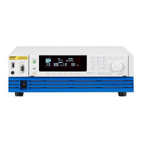
Kikusui PCR18000WE2R User Manual (246 pages)
AC power supply
Brand:
Kikusui
| Category:
Power Supply
| Size: 12 MB
Table of Contents
About Manuals
2
Notations Used in this Document
3
Checking the Package Contents
3
Safety Precautions
4
Precautions When Choosing the Installation Location
4
Moving the Product
4
Product Overview
5
Table of Contents
7
Component Names
10
Installation
16
Connecting the Power Cord
16
Connecting the PCR1000WE/PCR2000WE/PCR3000WE2
19
Connecting the PCR18000WE2/PCR24000WE2/ PCR30000WE2/PCR36000WE2
22
Turning the Power on
24
Preventing the Shutdown Function from Activating
24
Turning the POWER Switch on
25
Setting the Condition that the Product will be in When the POWER Switch Is Turned on
26
Turning the POWER Switch off
26
Connecting the Load
27
Connecting to the OUTPUT Terminal Block
28
Connecting the PCR1000WE/PCR2000WE
29
Connecting the PCR3000WE2
30
Connecting the PCR18000WE2/PCR24000WE2/ PCR30000WE2/PCR36000WE2
34
Basic Functions
37
Panel Operation Basics
37
Control Panel
37
Parts of the Screen
39
Explanation of Function Keys in this Manual
40
Home Position
40
Canceling Settings
40
Waiting for Confirmation
40
Busy Status
41
Returning the Product to the Factory Default Settings
41
Switching from Remote Mode to Local Mode
41
Displaying Single-Phase Three-Wire Output and Three-Phase Output (PCR-WE2 Only)
42
Specifying Values
44
Adjusting the Screen Brightness
45
Viewing the Firmware Version
46
Locking Panel Operations (Key Lock)
46
Selecting the Output Method
47
Setting the Output Voltage
48
Setting the Output Voltage Range
48
About Setting the Output Voltage
49
Output Voltage Setup Procedure for Single-Phase Output
51
Output Voltage Setup Procedure for Single-Phase Three-Wire Output
51
Output Voltage Setup Procedure for Three-Phase Output
53
Setting the Voltage Offset
54
Setting the Frequency
55
Turning the Output On/Off
56
Impedance When the Output Is off
57
Voltage Surge Suppression When the Output Is Turned off
58
Output On/Off Phase Control
59
AC Coupling
60
Measurement Display
61
Displaying the Voltage
61
Load Level Meter
63
Displaying the Current, Power, and Power Factor
64
Limit Function and Protection Function
66
Setting Limits
67
Upper and Lower Voltage Limits
67
Upper and Lower Frequency Limits
68
Current Limit and Peak Current Limits
68
Using Protection Functions
72
Using the Memory
74
Items that Can be Saved
74
Using Internal Preset Memory
75
Setting the Date and Time (Time Zone)
77
Using the Internal Setup Memory
78
Using a USB Memory Device
79
Advanced Functions
84
Using the Sync Function
84
Using the Compensation (Voltage Compensation) Function
86
Wiring the Hard Sensing and Soft Sensing Functions
88
Wiring the Regulation Adjustment Function
91
Compensation Function Setup Procedure
92
Ending the Use of the Compensation Function
95
Using Power Line Abnormality Simulations
96
Power Line Abnormality Simulation Setup Procedure
98
Executing and Stopping Power Line Abnormality Simulations
99
Using the Harmonic Analysis Function
100
Generating Special Waveforms (Waveform Bank)
101
Setting the Waveform Bank
102
Generating Special Waveforms
103
Setting the Output Impedance
104
Configuring Soft Start and Soft Stop
105
Configuring Soft Start
105
Configuring Soft Stop
106
Selecting the Response
107
Using the Power Management Functions
108
Sleep Function
108
Power-Saving Function
109
Power Module Management Function
110
Sequence Function
111
Sequence Overview
111
Editing Steps
116
Common Items
116
Frequency and AC Voltage
117
Execution Time, Waveform Bank
118
DC Voltage, Output
119
Status Output, Trigger Output, Trigger Input (Pause)
120
Jump Function
122
Starting Phase Angle, Ending Phase Angle, Sudden Phase Change
123
Output Impedance (for Single-Phase Output)
124
Output Impedance (for Single-Phase Three-Wire Output and Three-Phase Output, Resistance Component)
124
Output Impedance (for Single-Phase Three-Wire Output and Three-Phase Output, Reactance Component)
124
Phase Difference for Three-Phase Output
125
Setting Sequence Conditions
127
Executing, Pausing, and Stopping Sequences
128
Sequence Creation Tutorial
129
Sequence Creation Basics
131
Voltage Sweep and Frequency Sweep
134
Switching Steps at Specific Phase Angles
136
Suddenly Changing the Phase
139
Single-Phase Three-Wire Output and Three-Phase Output Basics
141
Phase Setting for Multi-Phase Output
142
Phase Sweep
146
Line Voltage Dip
148
External Control
150
Control Using Analog Signals
151
ANALOG in Connector Pin Arrangement
152
Selecting the Parameter to Control
153
Amplifying the Input Waveform (EXTDC Mode)
154
Varying the Output Voltage or Frequency Using DC Signals (VPROG Mode)
157
Control Using Digital Signals
161
DIGITAL I/O Connector Pin Arrangement and Mapping
162
Controlling the PCR-WE through External Contacts
165
Monitoring the Operation Status
170
Selectable I/O
173
Selectable Signals When INP.SIG Is Selected
175
Selectable Signals When OUTP.SIG Is Selected
175
Parallel Operation
176
Configuring the Master and Slave Units
177
Installation and Connection
178
Installation
178
Connecting PCR-Wes Together
178
Turning the Power on and Checking the Operation
182
Connecting the OUTPUT Terminal Block and Relay Terminals
182
Turning the Power on
183
Operation Check
183
Connecting the Load
184
Ending Parallel Operation
185
System Settings
186
Setting the Watchdog Protection (WDP)
186
Displaying/Changing the Interface Settings
187
Controlling the PCR-WE/WE2 from a PC
187
Displaying SCPI Errors
188
Factory Default Settings and Reset Settings
189
Factory Default Settings
190
Updating
195
Cleaning the Dust Filter
196
Maintenance
196
Backup Battery Replacement
198
Calibration
198
Specifications
199
Main Unit Specifications
199
Input (AC Rms)
200
Output
202
Output Voltage Stability (Phase Voltage)
203
Measurement
204
Limit Values and Protection Functions
205
Power Line Abnormality Simulations
206
Sequence Operations
206
Special Waveform Output
206
Output Impedance Setting
207
Output On/Off Phase Setting
207
Communication Interface
208
Signal I/O
209
Parallel Operation (PCR1000WE/ PCR2000WE/ PCR3000WE2 Excluded)
213
Memory
213
Sync Function
213
Compensation Function
213
Response Selection Function
214
Ecological Function
214
Soft Start and Soft Stop Functions
214
LIN, DSI Connection I/O
214
General
215
Rated Output Current Characteristics (Derating)
216
Outline Drawing
217
Appendix
220
Terminology
220
Power Regeneration Function (PCR-WE2R Only)
223
Output and Load
224
Rated Output Current for AC Output
224
AC Output Voltage Frequency Response
226
Frequency Response for Analog Input
226
Options
227
Input Power Cords
227
External Control Connector
228
Rack Mount Brackets
228
GPIB Interface Board (IB07-PCR-WE)
232
Base Hold Angles (OP03-KRC)
233
Parallel Operation Cables (PC01-PCR-WE, LC01-PCR-LE)
233
Troubleshooting
234
Alarms and Trouble
237
Overview
237
Remedy
238
Error Messages
240
Index
242
Advertisement
Advertisement
Related Products
Kikusui PCR18000LE2
Kikusui PCR18000WE2
Kikusui PCR18000WEA2
Kikusui PCR18000WEA2R
Kikusui PCR12000LE2
Kikusui PCR1000MA
Kikusui PCR1000WE
Kikusui PCR12000WE2
Kikusui PCR12000WE2R
Kikusui PCR1000M
Kikusui Categories
Power Supply
Test Equipment
Measuring Instruments
Racks & Stands
Extender
More Kikusui Manuals
Login
Sign In
OR
Sign in with Facebook
Sign in with Google
Upload manual
Upload from disk
Upload from URL