
Related Manuals for Kikusui PCR 2000M


Summary of Contents for Kikusui PCR 2000M
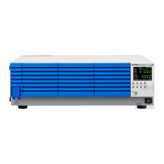
- Page 1 Part No. IB016983 May. 2010 USERʼS MANUAL AC POWER SUPPLY PCR-M series PCR 500M PCR1000M PCR2000M...
- Page 2 If you fi nd an y incorrectly arranged or missing pages in the manual, the y will be replaced. If the manual gets lost or soiled, a ne w cop y can be pro vided for a fee. In either case, please contact Kikusui distrib utor/ agent, and pro vide the “Kikusui P art No.
-
Page 3: Safety Symbols
Saf ety Symbols F or the saf e use and saf e maintenance of this product, the f ollo wing symbols are used throughout this man ual and on the product. Note the meaning of each of the symbols to ensure saf e use of the product. (Not all symbols ma y be used.) Indicates that a high v oltage (o v er 1 000 V) is used here . -
Page 4: Safety Precautions
Safety Precautions The following safety precautions must be observed to avoid fire hazards, electric shock, accidents, and other failures. Keep them in mind and make sure to observe them. Using the product in a manner that is not specified in this manual may impair the protection functions provided by the product. - Page 5 • To maintain the performance and safe operation of the product, it is recommended that periodic maintenance, inspection, cleaning, and calibration be performed. Service • Kikusui service engineers will perform internal service on the product. If the product needs adjustment or repairs, contact your Kikusui distributor/agent. PCR-M...
-
Page 6: How To Read This Manual
How to Read This Manual Introduction This manual is intended for first-time users of the PCR-M series. It gives an overview of the PCR-M series and describes various settings, measurement procedures, maintenance, safety precautions, etc. Read this manual thoroughly to use the functions of the PCR-M series effectively. You can also review this manual when you are confused about an operation or when a problem occurs. - Page 7 Structure of this manual Below is the structure of the manual. A summary of each chapter is provided. Chapter1 General Description This chapter gives a general description and introduces the features of the PCR-M. Chapter2 Installation and Preparation This chapter describes the procedures from unpacking to installation. Chapter3 Operation This chapter describes the operations of the PCR-M and procedure for controlling the output using external analog signals.
- Page 8 Notations used in the manual • In the interest of brevity, the PCR-M series AC power supply shall be hereafter referred to as the "PCR-M series" or the "power supply". • The word computer used in the text is a collective term for personal computers and workstations.
-
Page 9: Table Of Contents
Contents Safety Symbols - - - - - - - - - - - - - - - - - - - - - - - - - - - - - - - - - - - - - - - - - - - - - - - - - 3 Safety Precautions - - - - - - - - - - - - - - - - - - - - - - - - - - - - - - - - - - - - - - - - - - - - - - - 4 How to Read This Manual - - - - - - - - - - - - - - - - - - - - - - - - - - - - - - - - - - - - - - - - - 6 Contents - - - - - - - - - - - - - - - - - - - - - - - - - - - - - - - - - - - - - - - - - - - - - - - - - - - - - 9... - Page 10 Clearing Alarms - - - - - - - - - - - - - - - - - - - - - - - - - - - - - - - - - - - - - - - - -49 Clearing Errors - - - - - - - - - - - - - - - - - - - - - - - - - - - - - - - - - - - - - - - - - -49 Alarm or error number, description, and remedy - - - - - - - - - - - - - - - - - - 50 3.11.2 Operation when the protection function is activated - - - - - - - - - - - - -51...
-
Page 11: Contents By Function
Contents by Function Preparation Situation Heading page What is the input rating? section 2.6, “Connecting the Power Cord,” “Electrical specifications” How much space is necessary around the exhaust ports on section 2.2, “Precautions Concerning the rear panel? Installation Location” What kind of wires should be used to connect the load? section 2.8, “Connecting the Load”... -
Page 12: Front Panel
Front panel PCR500M PCR1000M PCR2000M Operation Panel ALARM OVER LOAD RANGE 135V 270V AUTO PEAK KEY LOCK REMOTE MEMORY PCR-M... - Page 13 Name Description +SHIFT Page POWER POWER switch. Push ( ) to turn on; push ( ) to turn off. Feet PCR500M: Four locations on the bottom PCR1000M / PCR2000M: Four locations on the bottom, four locations – on the side. OUTPUT outlet Front panel output Air inlet...
-
Page 14: Rear Panel
Rear panel PCR500M PCR1000M PCR2000M Name Description Page OUTPUT terminal block Output terminal block with a cover Air outlet Exhaust port for cooling – RS232C A connector for RS232C remote control Option slot Installs an option board. AC INPUT PCR500M: AC inlet PCR1000M / PCR2000M: AC input terminal block A connector for functional expansion –... - Page 15 General Description This chapter gives a general description and introduces the features of the PCR-M.
-
Page 16: Overview
Compact and light The reduction in size and weight can be enabled by using a PWM inverter method. PCR500M is approximately 1/5th in volume and 1/4th in weight with respect to Kikusui’s linear amplifier type AC power supplies. ● Memory function Up to three presets can be stored. -
Page 17: Options
Chapter 1 General Description Options Interface boards The functions below are expanded depending on the interface board that is installed in the PCR-M. • Selection of AC+DC mode in which DC power is superimposed on the AC power • Increased number of memory sets from 3 to 10. ■... - Page 18 Chapter 1 General Description Rack mount option Rack mounting options shown in Fig.1-1 are available. PCR500M KRA3 KRA150 Inch rack EIA standard Milli rack JIS standard PCR1000M / PCR2000M (Example : PCR1000M) KRB150-TOS KRB3-TOS Milli rack JIS standard Inch rack EIA standard Unit: mm (inch) Fig.1-1 Rack mount option...
- Page 19 Installation and Preparation This chapter describes the procedures from unpacking to installation.
-
Page 20: Checking The Package Contents
When you receive the product, check that all accessories are included and that the product and accessories have not been damaged during transportation. If any of the accessories are damaged or missing, contact your Kikusui agent or distributor. We recommend that all packing materials be saved, in case the product needs to be transported at a later date. -
Page 21: Precautions Concerning Installation Location
Chapter 2 Installation and Preparation Precautions Concerning Installation Location Be sure to observe the following precautions when installing the PCR-M. ● Do not use the product in a flammable atmosphere. To prevent the possibility of explosion or fire, do not use the product near alcohol, thinner or other combustible materials, or in an atmosphere containing such vapors. -
Page 22: Precautions To Be Taken When Moving The Product
Chapter 2 Installation and Preparation Precautions to Be Taken When Moving the Product Note the following points when moving or transporting the product to the installation location. ● Turn off the POWER switch. Moving the product while the power is turned on can cause electric shock or damage to it. - Page 23 Chapter 2 Installation and Preparation PCR1000M / PCR2000M Foot Rivet Handle Cover Bracket M4 flat-head screw (M4x0.7x0.8) Foot Rivet Screw pin Use the flat-head screwdriver to remove the pin. Fig.2-3 Removing the handle and feet (Example: PCR1000M) Removing the handle and feet Pull up on the handle cover (two locations).
-
Page 24: Attachment Of The Optional Interface Board
Chapter 2 Installation and Preparation Attachment of the Optional Interface Board Install an interface board to the option slot on the rear panel if you wish to control the PCR-M externally through an interface other than RS232C or control the output using external analog signals. -
Page 25: Connecting The Power Cord
If the supplied power cord cannot be used due to the rated voltage or the plug shape, have a qualified engineer replace it with an appropriate power cord of length 3 m or less. If obtaining a power cord is difficult, consult your Kikusui agent or distributor. - Page 26 Chapter 2 Installation and Preparation PCR1000M / PCR2000M When the power cord with the plug is attached to the PCR1000M, see the case of page 25 model PCR500M. The power cord attached to the PCR1000M (excluding the cord with plug) and the PCR2000M can be used either at 100Vac to 120 Vac or 200Vac to 240 Vac of the input voltage range.
- Page 27 Chapter 2 Installation and Preparation Check that the AC power supply meets the nominal input rating of the PCR1000M / PCR2000M. The voltage that can be applied is any of the nominal power supply voltages in the range of 100 Vac to 120 Vac or 200 Vac to 240 Vac. The frequency is 50 Hz or 60 Hz. •...
-
Page 28: Turning The Power On
Chapter 2 Installation and Preparation Turning the Power On Turning the POWER switch on Turn the power on without the load connected. Fig. 2-7 Check that the POWER switch is turned off ( ). Check that nothing is connected to the OUTPUT terminal block on the rear panel and the OUTPUT outlet on the front panel. - Page 29 Chapter 2 Installation and Preparation A L A R M O E R L O A D R A N G E E X T 1 3 5 2 7 0 Measured voltage A U T O R M S P E A K Alarm number M E M O R Y...
-
Page 30: Connecting The Load
Chapter 2 Installation and Preparation Connecting the Load Connecting to the OUTPUT terminal block ■ Preparation of Wire For connecting the load, use the noncombustible type of load wires which must be rated to carry the maximum rated output current. Table 2-1 Requirements for single-core cables used to connect to the load... - Page 31 Chapter 2 Installation and Preparation Connecting the load cables and attaching the Ferrite Core Attachment of the ferrite core is only PCR2000M. WARNING • There is a danger of electric shock. Do not use the terminal block with the terminal cover removed. CAUTION •...
-
Page 32: Connecting To The Output Outlet
Chapter 2 Installation and Preparation Connecting to the OUTPUT outlet The PCR-M can output power from the OUTPUT terminal block on the rear panel and the OUTPUT outlet on the front panel. Specifications are not defined for the OUTPUT outlet. A portion of the performance may be degraded. As for the PCR2000M, the output is shut down by the circuit breaker when it is over page 51 current. -
Page 33: When The Load Is Located At A Distance From The Pcr-M
Chapter 2 Installation and Preparation When the load is located at a distance from the PCR-M There may be the case in which the load is located at a distance to remote control the PCR-M. The remote control enables to turn the output off, but not for the POWER switch off. - Page 34 Chapter 2 Installation and Preparation PCR-M...
- Page 35 Operation This chapter describes the operations of the PCR-M and procedure for controlling the output using external analog signals.
-
Page 36: Switching The Output Mode
Chapter 3 Operation Switching the Output Mode The output mode can be switched between AC mode and DC mode when the page 40, 57 OUTPUT is turned off. If an optional interface board is installed in the option slot on the PCR-M rear panel, EXT mode (analog interface board only) and AC+DC mode can also be selected. -
Page 37: Setting The Voltage Range
Chapter 3 Operation Setting the Voltage Range The voltage range is switched with the OUTPUT turned off. The selectable voltage ranges are 135 V, 270 V, and AUTO. The RANGE key is disabled when the OUTPUT is turned on. Table Table indicate output... -
Page 38: Setting The Voltage
Chapter 3 Operation Setting the Voltage You can set the voltage regardless of whether the OUTPUT is on or off. If the voltage range is set to AUTO, the range automatically switches to 135 V or 270 V range according to the specified voltage. When the voltage range switches, the OUTPUT is turned off for approximately 0.5 seconds. -
Page 39: Setting The Frequency
Chapter 3 Operation Setting the Frequency Frequency setting is a function for AC mode and AC+DC mode. You can set the frequency regardless of whether the OUTPUT is on or off. The F key is disabled in DC mode. ALARM OVER LOAD RANGE 135V... -
Page 40: Turning The Output On/Off
Chapter 3 Operation Turning the OUTPUT On/Off The OUTPUT turns on/off each time the OUTPUT key is pressed. • OUTPUT on The LED above on the left of the OUTPUT key illuminates. The voltage and frequency according to the specified output mode and voltage range are output. - Page 41 Chapter 3 Operation ■ OUTPUT on phase angle The OUTPUT on phase can be set in AC mode. The control of the OUTPUT on phase angle is specified in the configuration. page 52 Because the output capacitor inside the PCR-M is discharged when there is no load, OUTPUT turns off at the zero-crossing phase.
-
Page 42: Measured Value Display
Chapter 3 Operation Measured value display The current output value is monitored. The upper numeric display indicates the current measured voltage, and the lower numeric display indicates the current measured current or power. Both displays indicate approximately 0 when the OUTPUT is off. - Page 43 Chapter 3 Operation Switching the display Table 3-6 shows how to switch to the measured value display from other setting displays. Table 3-6 Switching to measured value display Other Setting Display Switching Procedure Voltage setting display (V key illuminated) Press the V key. Frequency setting display (F key illuminated) Press the F key.
-
Page 44: Setting The Limit Value
Chapter 3 Operation Setting the limit value The limit function prevents damaging the load caused by operation errors by setting a limit on the output setting of the PCR-M. The limit value can be specified to match the load conditions in advance. The limit can be set regardless of whether the OUTPUT is on or off. - Page 45 Chapter 3 Operation • The limit value takes precedence over the setting value for voltage and frequency. If the current setting value exceeds the limit range when the voltage or frequency limit value is changed, the setting value (voltage or frequency) is set to a limit value that is closest to the current setting value.
-
Page 46: Using Memories
Chapter 3 Operation Using Memories The settings can be stored to memory. There are three memories, A, B, and C. Memories are effective when testing drastic changes in voltage or frequency. In case the optional interface board is installed in the optional slot on the rear panel, the setting condition can be stored up to 10 memories. -
Page 47: Recalling The Memory
Chapter 3 Operation Table 3-11 Stored settings Stored Settings Output mode (AC, DC, or EXT) Voltage range (135 V, 270 V, or AUTO) Voltage Frequency Measured value display (RMS, PEAK, AVG, or W) Limit values Voltage upper limit Voltage lower limit Current limit Frequency upper limit Frequency lower limit... -
Page 48: Locking (Prohibiting) The Panel Operation
Chapter 3 Operation 3.10 Locking (Prohibiting) the Panel Operation The operation from the panel can be locked to prevent the settings from being changed inadvertently when using the PCR-M with fixed voltage or frequency. When the panel is locked, all keys other than the OUTPUT and KEY LOCK (SHIFT+STORE) keys are disabled. -
Page 49: 3.11.1 Alarm Occurrence
Chapter 3 Operation 3.11.1 Alarm Occurrence When an alarm or error occurs, an alarm sounds and the ALARM LED on the display illuminates. The upper numeric display shows the output voltage, and the lower numeric display shows the alarm or error number. Alarm and overload ALARM OVER LOAD... -
Page 50: Alarm Or Error Number, Description, And Remedy
• If you cannot clear the alarm even when all of the causes of the alarm are eliminated, the PCR-M may have malfunctioned. Stop using the PCR-M and contact your Kikusui agent or distributor. When making an inquiry, please provide us with the displayed alarm or error number. -
Page 51: 3.11.2 Operation When The Protection Function Is Activated
Chapter 3 Operation 3.11.2 Operation when the protection function is activated The OVER LOAD LED on the display illuminates for conditions listed in Table 3- page 44, 49 , 14. The output voltage may vary while the OVER LOAD LED is illuminated. Table 3-14 Types of OVER LOAD LED illuminating OVER LOAD LED is illuminated Operation after an alarm occured... -
Page 52: Setting The Configuration
Chapter 3 Operation 3.12 Setting the Configuration The operating conditions are specified. Press the CONFIG key. The configuration setting display appears. The configuration setting switches in order each time the CONFIG key is pressed. Press the CONFIG key repeatedly until the operating condition you wish to set is displayed. - Page 53 Chapter 3 Operation OUTPUT on phase (ON.PH) Phase angle (PHAS) Measured value averaging (AVER) Peak hold time (HOLD) Communication interface type (INTF) RS232C baud rate GPIB address Vendor ID (BAUD) (ADRS) (VID) RS232C XON/XOFF Product ID control (PID) (F.CTL) Communication error trace function (TRAC) Measured...
- Page 54 Chapter 3 Operation OUTPUT on phase Set the OUTPUT on phase for AC mode. When using the OUTPUT on phase control, also set the phase angle. • OUTPUT on phase ON ( ): OUTPUT on phase control enabled OFF ( ): FREE operation (no phase control) •...
- Page 55 Chapter 3 Operation ■ RS232C If you select RS232C, set the baud rate and the XON/XOFF flow control. To activate the settings, the POWER switch must be turned off when at least 5 seconds elapses after changing the settings and then turned back on. •...
-
Page 56: Factory Default Settings (Initialization)
Chapter 3 Operation 3.13 Factory Default Settings (Initialization) If you turn the POWER switch on while holding down the RECALL key, all items listed in Table 3-15 are set to factory default settings. Table 3-15 Factory default settings Item PCR500M PCR1000M PCR2000M Output... -
Page 57: Controlling The Output Using External Analog Signals (Option)
Chapter 3 Operation 3.14 Controlling the Output Using External Analog Signals (Option) The output can be controlled using external analog signals by installing the analog interface board to the option slot. The analog interface board cannot be used together with the GPIB interface or USB interface. There are two available modes: EXT-AC mode in which the voltage of the output AC waveform (sine wave) is varied according to the input DC signal and EXT-DC mode in which the input waveform is simplify amplified and output. -
Page 58: Mode)
Chapter 3 Operation Names and functions of the parts of the analog interface board GAIN OFFSET INPUT Fig.3-15 Input terminal section Table 3-16 Names and functions Name Description BNC terminal for applying the external signal INPUT Input terminals is electrically isolated from the output terminals of the PCR-M. Input attenuator switch GAIN Variable resistor for fine adjusting the gain (voltage amplification ratio) -
Page 59: Amplifying The Input Waveform (Ext-Dc Mode)
Chapter 3 Operation Setting the limit value You can set the frequency limit (40 Hz to 500 Hz), the current limit, and the current page 44 limit operation (TRIP or LIMIT CONTROL). Table 3-17 Limit Value of EXT-DC mode PCR500M PCR1000M PCR2000M Limit value... - Page 60 Chapter 3 Operation Press the AC/DC/EXT key (SHIFT+V) to set the OUTPUT mode to page 36 EXT-DC. The EXT and DC LEDs illuminate. Press the RANGE key (SHIFT+I) to set the voltage range (135 V or 270 page 37 The LED corresponding to the voltage range illuminates. AUTO cannot be selected.
-
Page 61: Chapter 4 Remote Control
Remote Control This chapter gives an overview of remote control and describes how to install the instrument driver and software application. -
Page 62: Overview
Chapter 4 Remote Control Overview In addition to using the front panel, the PCR-M can be controlled remotely using the following interfaces. • RS232C interface • GPIB interface (option: IB21) • USB interface (option: US21) The remote interface complies with IEEE Std 488.2 1992 and SCPI Specification 1999.0. The functionality of the PCR-M is expanded by using the remote control function. -
Page 63: Installing The Visa Library
• Agilent VISA by Agilent Technologies (Agilent IO Libraries M01.00 or later) • KI-VISA Ver. 3.0.0 or later Installing KI-VISA KI-VISA is Kikusui's original VISA library that supports VXIplug&play VISA Specifications. The newest version can be downloaded from Download service of Kikusui website (http://www.kikusui.co.jp/en/download/). -
Page 64: Installing The Software Application
Chapter 4 Remote Control 4.2.2 Installing the Software Application This application Kikusui Easy Controller for PCR-M is an interactive virtual front panel program, which remote-controls your PCR-M. For detail, see “README(E)” in the accompanying CD-ROM. The following programs are also installed automatically along with the software application. -
Page 65: Chapter 5 Maintenance
Maintenance This chapter describes maintenance. Conduct periodic maintenance calibration maintain initial performance as long as possible. -
Page 66: Cleaning
Chapter 5 Maintenance Cleaning • Possible electric shock. May lead to death or injury. Before carrying WARNING out maintenance work, be sure to turn the POWER switch off and removing the plug of power cord from an outlet or turn off the circuit breaker of switchboard. - Page 67 Chapter 5 Maintenance Pull the lower tab of louver B while pressing it upward, slide the entire louver downward, and remove the louver from the panel. Lower tab Fig.5-2 Louver B removal Remove the dust filter from the inside of the louver and clean it. Dispose of foreign particles and dust from the dust filter using a vacuum cleaner.
-
Page 68: Calibration
Louver B Louver A 2nd level Fig.5-5 Louver A attachment Calibration The PCR-M is shipped after carrying out appropriate calibrations. We recommend periodic calibration to maintain the performance. For calibration, contact your Kikusui agent or distributor. PCR-M... -
Page 69: Troubleshooting
If you find an item that corresponds to your case, follow the remedy for the item. If page 56 you do not, we recommend that you initialize the PCR-M (memory contents are cleared). If the remedy does not correct the problem, contact your Kikusui agent or distributor. ■... - Page 70 Chapter 5 Maintenance ■ A portion or all of the control panel do not work. Check Item Check Possible Cause Remedy Release the panel lock. Is the KEYLOCK LED Key lock is enabled. section 3.10, “Locking (Prohibiting) illuminated? the Panel Operation.” Is the input voltage within the Set the input voltage so that it is within the Abnormal input voltage...
- Page 71 Specifications This chapter describes the electrical, mechanical, and optional interface board specifications of the PCR-M.
-
Page 72: Chapter 6 Specifications 6.1 Specifications
Chapter 6 Specifications Specifications Unless specified otherwise, the specifications are for the following settings and conditions. • The warm-up time is 30 minutes (with current flowing). • Typical value: Typical values do not guarantee the performance. • set: Indicates the setting. •... - Page 73 Chapter 6 Specifications PCR500M PCR1000M PCR2000M Output voltage stability Line voltage variation Within ±0.15 % Output current variation For 40 Hz to 100 Hz: Within ±0.15 V/±0.3 V (135 V/270 V range) For other frequencies: Within ±0.5 V/±1 V Output frequency variation *10 Within ±1 % Ripple noise *11 0.7 Vrms/1.4 Vrms (typical value)
-
Page 74: General Specifications
Chapter 6 Specifications General Specifications PCR500M PCR1000M PCR2000M Insulation Between input and chassis, 500 Vdc, 30 MΩ or more resistance output and chassis, input and output Withstand Between input and chassis, 1.5 kVac for 1 minute voltage output and chassis, input and output Earth continuity 25 Aac, 0.1 Ω... -
Page 75: Rs232C Interface Specifications
Chapter 6 Specifications RS232C interface specifications PCR-M Series Complies with EIA-232-D D-SUB 9-pin connector (male) *1 Hardware Baud rate: 1 200, 2 400, 4 800, 9 600, or 19 200 bps Data length: 8 bits, stop bit: 1 bit, and parity bit: None Flow control: Xon/Xoff Program message terminator LF during reception, CR/LF during transmission... -
Page 76: Analog Interface Specifications (Ex04-Pcr-M Option)
Chapter 6 Specifications Analog interface specifications (EX04-PCR-M option) Total performance when the EX04-PCR-M is installed in the PCR-M. Items not listed below conform to the specifications of the PCR-M. PCR-M series Maximum allowable input voltage ±15 V Type Input terminal Input impedance 10 kΩ... -
Page 77: Dimensions
Chapter 6 Specifications Dimensions PCR500M Feet, M3 screw holes 95(3.75) 95(3.75) (0.94) 214(8.43) 4-M3 screw holes (Max. depth 6 mm(0.24 inch)) Unit: mm (inch) 4-ø5(0.20) (Mounting holes for feet) 150(5.91) (1.26) (1.26) 170(6.70) 22(0.87) 22(0.87) Fig.6-1 PCR500M outline drawing PCR1000M Feet, M3 screw holes 4-M4 screw holes... - Page 78 Chapter 6 Specifications PCR2000M Feet, M4 screw holes 4-M4 screw holes 52(2.05) 52(2.05) MAX450(17.72) (1.06) (2.76) (1.22) (Max. depth 8 mm 429(16.89) MAX15 24(0.94) (0.31 inch)) (0.59) 4-ø5(0.20)(Mounting holes for feet) 4-M3 screw holes (Max. depth 6 mm(0.24 inch)) 365(14.37) 32(1.26) 32(1.26) Unit: mm (inch)
-
Page 79: Appendix
Appendix... -
Page 80: Output And Load
Appendix Output and Load Rated output current of AC mode For linear loads The rated AC output current of the PCR-M is limited by the PCR-M output capacity as shown in the graph of Fig. A-1. Table A-1 Output capacity of AC mode PCR500M PCR1000M PCR2000M... - Page 81 Appendix If the PCR-M is used with a current exceeding the maximum rated peak current or the maximum current, the protection function of the PCR-M activates and may extremely distort the output voltage waveform or cut off the output. To supply the maximum peak current above, hold the output voltage (setting) constant.
-
Page 82: Rated Output Current Of Dc Mode
Appendix Rated output current of DC mode The rated DC output current that can be drawn from the PCR-M is limited by the PCR-M output capacity as shown in the graph of Fig. A-3. Table A-2 Output capacity of DC mode PCR500M PCR1000M PCR2000M... - Page 83 Appendix Causes of and remedies for overload status If the overload protection function is activated, take the remedies below. Then, wait at least 1 minute before resuming operations. When the cause of the overload is eliminated, the protection function is automatically deactivated.
-
Page 84: Ac+Dc Mode
Appendix Voltage waveform Normal operation When the current limit function is activated Voltage waveform Voltage waveform Normal operation Normal operation When the internal When the internal protection function protection function is activated is activated (b-1) (b-2) Current waveform Voltage waveform Fig.A-4 Overload condition AC+DC mode... -
Page 85: Glossary
Appendix Glossary Rated output (power) capacity or power capacity The maximum value (unit: VA) of the output power capacity that can be continuously supplied when the output voltage is 100 V to 135 V (for the 135 V range) or 200 V to 270 V (for the 270 V range) and the output frequency is 40 Hz to 500 Hz in AC mode or when the output voltage is 100 V to 190 V (for the 135 V range) or 200 V to 380 V (for the 270 V range) in DC mode. - Page 86 Appendix Capacitor-input rectifying load Resistive load Fig.A-6 Output current waveform example Output voltage waveform distortion ratio The total harmonic distortion factor (%) of the output voltage waveform when the output voltage is 50 V to 135 V (for the 135 V range) or 100 V to 270 V (for the 270 V range) and the load power factor is 1.
- Page 87 Appendix Power factor (PF) The power factor is the ratio of the active power with respect to the apparent power. It indicates the level of degradation in the efficiency caused by the phase difference between the AC voltage and AC current. Active power Power factor = Apparent power...
- Page 88 Appendix Active filter A circuit used to reduce the input current distortion factor (harmonic current). This filter is used in the input power-supply block of the PCR-M. It is a switching- controlled active filter. The use of the filter improves the power factor (0.9 (typical value)).
-
Page 89: Index
Index AC mode 36 GPIB address 55 AC+DC mode 36 GPIB interface board 17 accessories 20 alarm or error number 50 alarms, clearing of 49 initialization 56 analog interface board 17 interface board averaging period 54 attachment of 24 Breaker button 51 LIMIT CONTROL 45 limit value 44 loads that draw an inrush current 81... - Page 90 panel operation, locking of 48 panels, cleaning of 66 peak hold time 54 phase angle 54 power cord 25 Power factor 87 Product ID 55 rack mount frame 18 attachment to 22 rated maximum current 85 rated output (power) capacity 85 rated output current 85 remote control 54 RS232C baud rate 55...
- Page 91 PCR-M...
Need help?
Do you have a question about the PCR 2000M and is the answer not in the manual?
Questions and answers