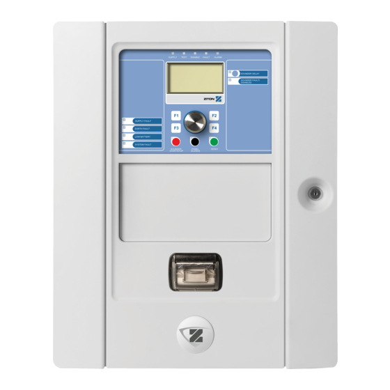
Ziton ZP2 Series Quick Installation Manual
Hide thumbs
Also See for ZP2 Series:
- Installation manual (148 pages) ,
- Operation manual (35 pages) ,
- Protocol manual (15 pages)
Table of Contents
Advertisement
Quick Links
ZP2 Series Quick Installation Guide
Overview
This document includes quick installation information for your
control panel. For detailed installation information (including
EN 54-13 requirements) and for configuration options, see the
product installation manual.
WARNING:
Electrocution hazard. To avoid personal injury or
death from electrocution, remove all sources of power and
allow stored energy to discharge before installing or removing
equipment.
Caution:
Equipment damage hazard. This product is sensitive
to electrostatic discharge (ESD). To avoid damage, follow
accepted ESD handling procedures.
Adding the menu inserts
Add the control panel interface menus as shown below.
The inserts are numbered 1, 2, 3, and 4, and are inserted at
the location indicated (with the printed area facing the front of
the control panel).
For evacuation panels, remember to add descriptions for any
output groups assigned to the programmable buttons to
insert 3.
Note:
Different versions of insert 3 are provided for fire panels
and for evacuation panels, and each is marked with the
corresponding control panel product code. Be sure to use the
correct version of the insert for your product.
© 2013 UTC Fire & Security. All rights reserved.
Installing the cabinet
Where to install the control panel
Install the control panel in a location that is free from
construction dust and debris, and immune to extreme
temperature ranges and humidity.
Provide enough floor and wall space to allow the control panel
to be installed and serviced without any obstructions. The
cabinet should be mounted so that the user interface is at eye
level.
Fixing the cabinet to the wall
Fix the cabinet to the wall using five M4 × 30 screws and five
Ø 6 mm wall plugs, as shown below.
1.
Hold the cabinet to the wall at the required installation
height.
2.
Ensure that the cabinet is level using the built-in spirit level
and mark drill points on the wall.
3.
Drill all required holes and insert a 6 mm wall plug into
each.
4.
Insert a screw in position (1) and hang the cabinet onto
this screw.
5.
Insert screws in positions (2) and tighten.
6.
Insert screws in position (3) and tighten.
7.
Tighten screw in position (1).
1 / 2
P/N 501-405203-4-30 • REV 03 • ISS 23FEB13
Advertisement
Table of Contents

Subscribe to Our Youtube Channel
Related Manuals for Ziton ZP2 Series


Summary of Contents for Ziton ZP2 Series
-
Page 1: Adding The Menu Inserts
ZP2 Series Quick Installation Guide Overview Installing the cabinet This document includes quick installation information for your Where to install the control panel control panel. For detailed installation information (including EN 54-13 requirements) and for configuration options, see the Install the control panel in a location that is free from product installation manual. - Page 2 Overview of typical fire system connections using a single Class A loop Connecting loops and loop devices Mains fuse and batteries For optimal system performance, we recommend a twisted-pair Use a T4A-250V mains fuse for both 110 VAC and 240 VAC loop cable, 12 to 26 AWG (0.13 to 3.31 mm²), with 75 Ω...
Need help?
Do you have a question about the ZP2 Series and is the answer not in the manual?
Questions and answers