Table of Contents
Advertisement
Quick Links
Advertisement
Table of Contents

Related Manuals for Ziton ZR4ST-3


Summary of Contents for Ziton ZR4ST-3
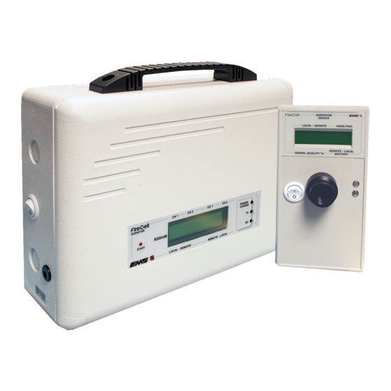
- Page 1 LOCAL - REMOTE PASS / FAIL REMOTE - LOCAL SIGNAL QUALITY % BATTERY CH 1 CH 2 CH 1 CH 2 POWER/ CHARGE RSSI/dB START LOCAL - REMOTE REMOTE - LOCAL ZR4ST-3 SURVEY KIT USER GUIDE TSD256 (Iss 6) www.acornfiresecurity.com...
-
Page 2: Table Of Contents
Typical Ziton Hub/RCC System Overview Hub/RCC System Survey Guidelines 17-18 Step By Step Guide - Hub/RCC to RCC Surveying Hub/RCC to RCC Survey Form 20-21 Step By Step Guide - Ziton Device to RCC Surveying Ziton Device to RCC Survey Form www.acornfiresecurity.com... -
Page 3: Start
www.acornfiresecurity.com Start www.acornfiresecurity.com... -
Page 4: Introduction
The survey will create the foot print for the installed system, specifying the nal positions for the devices and wireless infrastructure. The Ziton wireless survey kit has been designed so that it can survey both Ziton and Ziton Radio Loop Module (RLM) systems. -
Page 5: About The Survey Kit
www.acornfiresecurity.com About The Survey Kit www.acornfiresecurity.com... -
Page 6: Survey Kit Overview
www.acornfiresecurity.com Survey Kit Overview SURVEYOR Pole Mounted Survey Tool (1 per kit) DEVICE LOCAL - REMOTE PASS / FAIL This part of the survey equipment when used in conjunction with the Signal REMOTE - LOCAL SIGNAL QUALITY % BATTERY Surveyor Unit, identi es accurate signal strength information between the two points. -
Page 7: Signal Surveyor Features
www.acornfiresecurity.com Signal Surveyor Features Carry handle LCD display On / O CH 1 CH 2 CH 1 CH 2 switch POWER/ Power, transmit CHARGE RSSI/dB START and receive LEDs Charger LOCAL - REMOTE REMOTE - LOCAL connection Using the Signal Surveyor CH 1 CH 2 CH 1... -
Page 8: Signal Surveyor Battery Replacement
www.acornfiresecurity.com Signal Surveyor Battery Replacement The Signal Surveyor’s mains charger can be left connected if necessary, during the survey process. The rated charging voltage is between 100 – 230Vac +/- 10%; 0.3A at 45-65Hz. Should the internal battery require replacement, correct polarity must be observed as marked on the battery (Y4-6 6V, 4Ah C20) red wire = positive, black wire = negative. -
Page 9: Using The Device Survey Tool
LED signal indication is also shown on the device, a Green LED indicates a Pass and the Yellow LED indicates a Fail. Whether undertaking a Ziton RLM or Ziton Hub/RCC survey, a level of 24dB or above is required as a pass result. -
Page 10: Ziton Rlm Survey
www.acornfiresecurity.com RLM Survey www.acornfiresecurity.com... -
Page 11: Ziton Rlm Survey Objectives
Ziton RLM Survey Objectives Identify all Ziton RLM positions. Prove all wireless device communications are above 24dB and indicate a pass. Typical Ziton RLM System Overview 31 Devices per RLM 31 Devices per RLM POWER POWER FAULT FAULT ISOLATOR... - Page 12 www.acornfiresecurity.com 2. Remember when choosing a location, the RLMs require a loop in and out cable connection and a maximum of ve RLMs per loop are allowed. Max 2 RLMs POWER POWER FAULT FAULT ISOLATOR ISOLATOR ACTIVE ACTIVE LOOP INTERFACE LOOP INTERFACE per loop SUPPLY...
- Page 13 www.acornfiresecurity.com 4. Consider positioning your RLMs centrally, giving as much 360 degree coverage as possible. Position POWER FAULT ISOLATOR ACTIVE LOOP INTERFACE 5. Remember, the RLMs can each accommodate a maximum of 31 wireless devices. Max 31 devices POWER FAULT ISOLATOR ACTIVE LOOP INTERFACE...
-
Page 14: Step By Step Guide - Ziton System Survey
Step By Step Guide - Ziton System Survey Note: a Ziton RLM Survey Form is supplied on page 15. Step 1. Surveyor Position the Signal Surveyor in the proposed RLM location. in RLM position CH 1 CH 2 CH 1... -
Page 15: Ziton Rlm Survey Form
Ziton RLM Survey Form Site Customer name Survey date Company Surveyor name RLM number Background Level Device No Signal Level Pass Fail Comments CH 2 POWER/ CHARGE REMOTE - LOCAL www.acornfiresecurity.com... -
Page 16: Ziton Hub/Rcc Survey
www.acornfiresecurity.com Hub/RCC Survey www.acornfiresecurity.com... -
Page 17: Ziton Hub/Rcc Survey Objectives
Identify Hub and all RCC positions. Prove all Hub/RCC wireless communications are above 24dB and indicate a pass. Prove all wireless device communications are above 24dB and indicate a pass. Typical Ziton Hub/RCC System Overview 31 Devices per RCC Hop 2... - Page 18 www.acornfiresecurity.com 2. All Devices must have valid communication to an RCC (Pass Result). Pass Pass Pass POWER FAULT 3. Maximum 31 RCCs. Radio Pass Pass POWER POWER POWER POWER FAULT FAULT FAULT FAULT SUPPLY TEST DISABLE FAULT ALARM SOUNDER DELAY Max 31 RCCs SOUNDER FAULT / SUPPLY FAULT...
-
Page 19: Step By Step Guide - Hub/Rcc To Rcc Surveying
Step By Step Guide - Ziton Hub/RCC to RCC Surveying Note: a Hub/RCC to RCC Survey Form is supplied on page 20. Step 1. Surveyor Position the Signal Surveyor in the proposed Radio Hub in Hub location. position CH 1... -
Page 20: Hub/Rcc To Rcc Survey Form
Ziton Hub/RCC to RCC Survey Form Site Customer name Survey date Company Surveyor name Fire Panel and Radio Hub. Location EXAMPLE Main Corridor Location CH 2 POWER/ Comms Path Talks to: Pass Fail CHARGE Signal Level REMOTE - LOCAL... - Page 21 www.acornfiresecurity.com Location Comms Path Talks to: Pass Fail Signal Level Background Level Location Comms Path Talks to: Pass Fail Signal Level Background Level Location Comms Path Talks to: Pass Fail Signal Level Background Level Location Comms Path Talks to: Pass Fail Signal Level Background Level...
-
Page 22: Step By Step Guide - Ziton Device To Rcc Surveying
Step By Step Guide - Ziton Device to RCC Surveying Note: a Device to RCC Survey Form is supplied on page 23. Step 8. Surveyor Device to RCC coverage must now be proven. Position the in RCC Signal Surveyor in the proposed RCC location. -
Page 23: Ziton Device To Rcc Survey Form
Ziton Device to RCC Survey Form RCC number Additional notes Device No Signal Level Pass Fail Comments www.acornfiresecurity.com...
Need help?
Do you have a question about the ZR4ST-3 and is the answer not in the manual?
Questions and answers