
Related Manuals for Interlogix TruVision TVB2406


Summary of Contents for Interlogix TruVision TVB2406
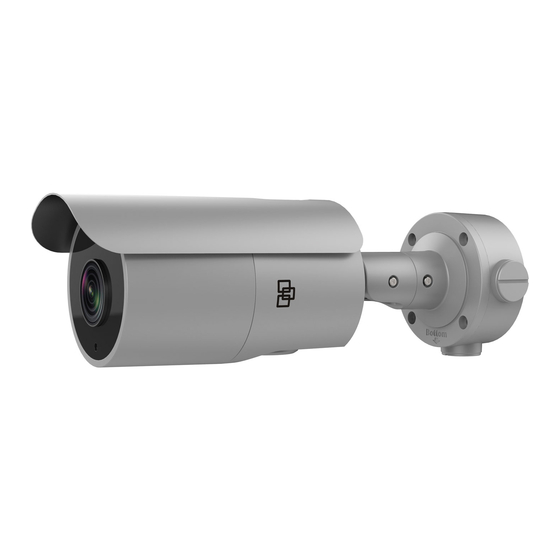
- Page 1 TruVision High Resolution TVI Bullet IR Camera TVB- 2406/TVB-4406 Installation Guide P/N 1073163-EN • REV B • ISS 06DEC17...
-
Page 3: Table Of Contents
Contents Overview ............. 2 Description ..........5 Installation ........... 7 Operating temperature range ..... 10 Program ............ 11 Menu tree ..........16 Specifications ..........17 Legal ............18... -
Page 4: Overview
Overview This is the TruVision High Resolution TVI Bullet IR Camera Installation Guide for the camera model TVB-2406/TVB-4406. This guide describes a standard installation. TVB-4406 (TruVision HD-TVI Analog Bullet Camera, 1080p, 5 to 50 mm Motorized VF Lens, NTSC) TVB-2406 TruVision HD-TVI Analog Bullet ... - Page 5 Camera with power 4 screws and 4 and video output anchors for wall or cables ceiling installation Screws M4.8 × 18, Back box 4 pcs to attach the back box Template Hex wrench ...
- Page 6 • • Installation guide • WEEE and battery • Video test cable disposal...
-
Page 7: Description
Description Power cable 960H analog output (black) TVI output (gray) Mounting bracket Camera body Sun shield Lens cover Back box... - Page 8 Note: When making adjustments to the VF lens bullet camera, it is important to tighten the access cover for the area that contains the video test cable connector, OSD menu button, and the 960H analog/WDR/TVI selection switch. The access cover should be rotated until it is tight up against the camera body.
-
Page 9: Installation
Video test cable connector OSD button Switch (Up = CVBS/960H analog Down = WDR) Installation To install the camera Using the template, place it level against the mounting surface and mark the position of the mounting holes. - Page 10 Following all local safety regulations, drill and prepare the mounting holes. As an optional step, install the back box on the wall.
- Page 11 Route the cables to the cable hole and connect the corresponding cables. Using a 75-ohm coaxial video cable, connect the camera’s TVI video output to a TVI DVR, and connect a 12 VDC or 24 VAC power supply to the power cable.
-
Page 12: Operating Temperature Range
Loosen the three screws and adjust the camera according to the figure below to get an optimum angle. Tighten the screw after completing the adjustment. 360° 90° 360° Using the zoom and focus buttons on the PTZ panel of the connected recorder, adjust the camera’s zoom and focus. -
Page 13: Program
You can configure the heater option in the OSD menu under SET UP > SPECIAL > HEATCTRL. There are three options: Off: Heater is disabled. Auto: The heater starts to work when the temperature falls below -10 °C (14° F). When temperature increases to -5 °C (23 °F), it will stop working. - Page 14 Using the buttons Menu Please press the button to call up the OSD menu and select an OSD item. Press the button up/down to move the cursor up or down to an OSD item. Press the button left/right to move the cursor left or right to adjust the value of a selected OSD item.
- Page 15 Figure 1: TVI cable connection Access the PTZ menu of the connected DVR. Set TruVision-Coax protocol and use the PTZ control panel to configure the camera. Iris+ Click to access to the camera OSD menu and select an OSD item. Click the directional buttons UP or DOWN to move the cursor up or down to an OSD item.
- Page 16 When the Auto-focus feature is enabled, the camera can automatically adjust itself to achieve the best focus. For more details, refer to the TVI DVR user manual. Using a CVBS output A TVS-C200 (purchase separately) can be used to program the camera over its CVBS output, not the TVI video output.
- Page 17 Figure 2: CVBS cable connections Press the button of the TVS-C200 for a few seconds until you see the OSD menu display on the monitor. The OK button is also used for selecting an OSD item. Use the directional buttons to move the cursor and adjust a value.
-
Page 18: Menu Tree
Menu tree... -
Page 19: Specifications
Specifications Power supply 12 VDC / 24 VAC Current 12 VDC: 1.67 A max. 24VAC: 83 mA max. Power 20 W max. consumption Temperature 24 VAC: -40 to +60 °C (-40 to +140 °F) with heater on 12 VDC: -30 to +60 °C (-22 to +40 °F) Weight (net) 1.59 kg / 3.5 lb. -
Page 20: Legal
Legal Copyright: © 2017 United Technologies Corporation, Interlogix is part of UTC Climate, Controls & Security, a unit of United Technologies Corporation. All rights reserved. Trademarks and patents: Trade names used in this document may be trademarks or registered trademarks of the manufacturers or vendors of the respective products. - Page 21 harmful interference to radio communications. Operation of this equipment in a residential area is likely to cause harmful interference in which case the user will be required to correct the interference at his own expense. ACMA compliance Notice! This is a Class A product. In a domestic environment this product may cause radio interference in which case the user may be required to take adequate measures.
- Page 22 For more information on warranty disclaimers and product safety information, please check www.firesecurityproducts.com/policy/product-warning/ or scan the following code: Contact information and manuals : For contact information go to: www.interlogix.com or www.firesecurityproducts.com To get translations for this and other product manuals go to: www.firesecurityproducts.com...
Need help?
Do you have a question about the TruVision TVB2406 and is the answer not in the manual?
Questions and answers