
Subscribe to Our Youtube Channel
Related Manuals for Interlogix TruVision TVB-4409


Summary of Contents for Interlogix TruVision TVB-4409
- Page 1 TruVision HD-TVI 5MPX Camera Installation and Configuration Manual P/N 1073359-EN • REV B • ISS 18AUG17...
- Page 2 Copyright © 2017 United Technologies Corporation. Interlogix is part of UTC Climate, Controls & Security, a unit of United Technologies Corporation. All rights reserved. Trademarks and Trade names used in this document may be trademarks or registered patents trademarks of the manufacturers or vendors of the respective products.
-
Page 3: Table Of Contents
Content Important information 2 Limitation of liability 2 Advisory messages 2 Introduction 3 Product overview 3 Installation 4 Installation environment 4 Package contents 5 Camera description 9 Mounting the HD-TVI fixed lens bullet camera 11 Mounting the HD-TVI VF motorized lens bullet camera 14 Mounting the HD-TVI fixed lens turret camera 16 Mounting the HD-TVI VF motorized lens turret camera 19 Mounting the HD-TVI VF motorized lens dome camera 23... -
Page 4: Important Information
Important information Limitation of liability To the maximum extent permitted by applicable law, in no event will UTCFS be liable for any lost profits or business opportunities, loss of use, business interruption, loss of data, or any other indirect, special, incidental, or consequential damages under any theory of liability, whether based in contract, tort, negligence, product liability, or otherwise. -
Page 5: Introduction
Introduction Product overview This is the installation guide for TruVision 5MPX HD-TVI camera models: HD-TVI fixed lens bullet camera: TVB-2409 (5MPX Bullet, 3.6 mm lens, PAL) TVB-4409 (5MPX Bullet, 3.6 mm lens, NTSC) HD-TVI VF motorized lens bullet camera: ... -
Page 6: Installation
Installation This section provides information on how to install the cameras. Installation environment Please keep in mind that there are restrictions/rules when using the HD-TVI 5MPX cameras with TruVision TVI recorders: The TVI 5MPX cameras only work with the higher resolution TVI recorders (TVR 15HD or TVR 45HD, or higher), firmware version 1.1 (or higher) ... -
Page 7: Package Contents
Package contents Check the package and contents for visible damage. If any components are damaged or missing, do not attempt to use the unit; contact the supplier immediately. If the unit is returned, it must be shipped back in its original packaging. HD-TVI fixed lens bullet camera ... - Page 8 • Video test cable • 4 screws (M4.8 × 18). Used with the back box • Plastic G3/4 cable adapter Mounting template Ceiling Mounting 1:Screw Hole for 2:Screw Hole for Bracket Mounting Base (mm) • CD Installation guide • Equipment disposal sheet (WEEE directive) HD-TVI fixed lens turret camera •...
- Page 9 • 4 screws (KM4 × 8). Used to attach • 3 screws (PM4 × 8). Used to attach the turret camera to the bracket the turret camera to the adapter) • CD • Installation guide • Equipment disposal sheet (WEEE directive) HD-TVI VF motorized lens turret camera ...
- Page 10 • CD Adapter plate • Equipment disposal sheet (WEEE directive) HD-TVI VF motorized lens dome camera 3 screws (4 × 25 mm) and 3 anchors Camera with power and video output (7.5 × 24.5 mm) cable harness •...
-
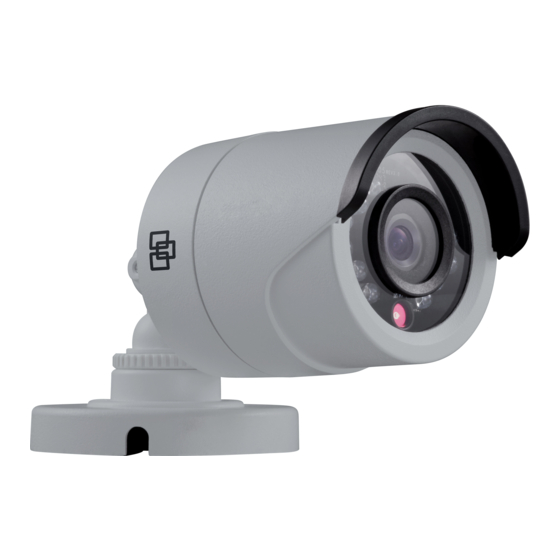
Page 11: Camera Description
• Equipment disposal sheet (WEEE directive) Camera description Figure 1: HD-TVI fixed lens bullet camera 1. TVI output 4. Camera body 2. 12 VDC power 5. Lens 3. Mounting base 6. IR LEDs Figure 2: HD-TVI VF motorized lens bullet camera 1. - Page 12 TVI output OSD menu button Note: When making adjustments to the motorized lens bullet camera, it is important to tighten the access cover (7) for the area that contains the video test cable connector and OSD menu button. The access cover should be rotated until it is tight up against the camera body.
-
Page 13: Mounting The Hd-Tvi Fixed Lens Bullet Camera
4. Base Figure 5: HD-TVI VF motorized lens dome camera 1. Bubble 5. 12 VDC/24 VAC power 2. Video test cable 6. Lens assembly 3. OSD (5-direction) button 7. Base 4. TVI output Mounting the HD-TVI fixed lens bullet camera Surface mount 1. - Page 14 5. Connect the corresponding cables. 6. Adjust the camera to get the best viewing angle. See the figure below. Pan position range: 0-360° P (pan) adjustment T (tilt) adjustment R (rotation) adjustment Rotation position range: 360° Tilt position range: 0-180° a) Loosen the P adjustment disk to adjust the pan direction [0-360°].
- Page 15 3. Place the mounting template level against the mounting surface and mark the position of the mounting holes. Use the ‘UP’ marking on the back box and camera mounting base as a reference. 4. Following all local safety regulations, drill and prepare the mounting holes. 5.
-
Page 16: Mounting The Hd-Tvi Vf Motorized Lens Bullet Camera
Mounting the HD-TVI VF motorized lens bullet camera Surface mount when not using the supplied back box 1. Use the supplied template to mark out the mounting area. 2. Following all local safety regulations, drill and prepare the mounting and cable access (if required) holes. - Page 17 c) Loosen the R screw and rotate the camera [0-360°] to adjust the lens to the desired surveillance angle. Tighten the screw after completing the adjustment. Surface mount when using the back box 1. Remove the cover from the back box and align the screw holes of the bullet camera with the holes in the back box cover.
-
Page 18: Mounting The Hd-Tvi Fixed Lens Turret Camera
7. Refer to step 6 of “Surface mount when not using the supplied back box” on page 14 to adjust the camera to the desired viewing angle. Mounting the HD-TVI fixed lens turret camera Surface mount 1. Disassemble the turret camera by rotating the trim ring, as shown below. 2. - Page 19 If installing the turret camera to a wall mount or other accessory, an adapter plate is provided. Install the adapter plate to the accessory with three PM4 x 8 screws, referencing number "2". 8. Adjust the camera to get the best viewing angle. See figure below. Pan position range: 0-360°...
- Page 20 2. Remove the cover from the back box. 3. Place the provided template level against the mounting surface and mark the position of the mounting holes. 4. Following all local safety regulations, drill and prepare the mounting holes. 5. Route the cables through the cable access hole of the back box. Mount the camera to the cover of the back box.
-
Page 21: Mounting The Hd-Tvi Vf Motorized Lens Turret Camera
9. Refer to page 17 to adjust the camera to the desired viewing angle. Mounting the HD-TVI VF motorized lens turret camera Surface mount 1. Place the provided template level against the mounting surface and mark the position of the mounting holes. 2. - Page 22 6. Reassemble the turret camera by rotating the trim ring back on the camera, as shown below. Helpful hints when mounting the turret camera: a) Mount the turret base to a surface. b) When mounting on a wall, aim the lens towards the floor and the UP marking on the camera assembly towards the ceiling.
- Page 23 Pan position range: Tilt position range: 0-360° 0-75° Rotation position range: 0-360° Surface mount when using the optional back box 1. Remove the cover from the back box. 2. Place the provided template level against the mounting surface and mark the position of the mounting holes.
- Page 24 6. Install the back box to the mounting surface using the hardware provided. 7. Connect the corresponding cables and install the back box cover and camera to the back box. 8. Rotate the trim ring back on to the camera body, as shown by the arrow. 9.
-
Page 25: Mounting The Hd-Tvi Vf Motorized Lens Dome Camera
Mounting the HD-TVI VF motorized lens dome camera Surface mount 1. Place the provided template level against the mounting surface and mark the position of the mounting holes. 2. Following all local safety regulations, drill and prepare the mounting holes. 3. - Page 26 a) View the camera image on a monitor. b) Rotate the panning table to adjust the pan direction [0 to 355°]. c) Move the lens assembly up or down to adjust the tilt position [0 to 90°]. d) Rotate the camera lens holder [0 to 355°] to adjust the lens to the surveillance angle.
-
Page 27: Programming
Programming Once the camera hardware has been installed, configure the camera using the built-in OSD button (if supported) and the TVI DVR menu. The TVS-C200 controller (Service Tool) does not support the 5MPX cameras. You can also configure the camera settings via a TVI DVR. Select the PTZ protocol TruVision Coax and click the menu button to call up the menu. -
Page 28: Menu Trees
The camera setup menu appears (see “Menu trees” on page 26 for the menu structure). 5. Select the menu options: From the DVR: To select an OSD item, click the directional buttons up/down. To adjust the value of a selected item, click the directional buttons left/right. From the camera (if it has a menu button): To select an OSD item, push the Menu button up/down. -
Page 29: Tvb-2410/4410, Tvt-2404/4404, And Tvd-2406/4406 Cameras
TVB-2410/4410, TVT-2404/4404, and TVD-2406/4406 cameras TruVision HD-TVI 5MPX Camera Installation and Configuration Manual... -
Page 30: Configuration
Configuration This section describes how to set up the menu settings. Output Mode Move the cursor to OUTPUT MODE, and press the Menu button to enter the submenu. Set the RESOLUTION, FRAME RATE, and NTSC/PAL of the camera and confirm. OUTPUT MODE 5 MEGA RESOLUTION... -
Page 31: Language
Language Select either ENGLISH or CHINESE as the system language. Main Menu Use the Main menu to adjust the image-related parameters, including EXPOSURE, WHITE BALANCE, DAY/NIGHT, and VIDEO SETTINGS. SET UP EXPOSURE WHITE BALANCE DAY / NIGHT VIDEO SETTINGS RESET SAVE &... - Page 32 conditions. Set the AGC value between 0 and 15. AGC is disabled when the value is set to 0. DWDR DWDR mode (Digital Wide Dynamic Range) helps the camera provide clear images even under backlight circumstances. When there are both very bright and very dark areas simultaneously in the field of view, DWDR balances the brightness level of the whole image and provides clear images with detail.
- Page 33 DAY/NIGHT AUTO MODE INFRARED SMART IR BACK INFRARED: Select to turn on/off the IR LED depending on the lighting conditions. SMART IR: Use this to avoid over exposure of an image due to IR LED glare. Adjust the SMART IR value between 0 and 3.
- Page 34 when the camera needs to be installed upside down. Select one of the functions: DEFAULT: The mirror function is disabled. H: The image flips 180 degrees horizontally. V: The image flips 180 degrees vertically. HV: The image flips 180 degrees both horizontally and vertically. Reset Reset all the settings to the default.
-
Page 35: Specifications
Specifications Power supply 12 VDC / 24 VAC Current TVB-2409/TVB-4409: 12 VDC: Max. 290 mA TVB-2410/TVB-4410: 12 VDC: Max. 790 mA / 24 VAC: Max.660 mA TVT-2403/TVT-4403: 12 VDC: Max. 250 mA TVT-2404/TVT-4404: 12 VDC: Max. 750 mA TVD-2406/TVD-4406: 12 VDC: Max. 580 mA / 24 VAC: 416 mA Power consumption TVB-2409/TVB-4409:... - Page 36 Dimensions TVB-2409/TVB-4409: 58.2 × 154.5 mm / 2.3 × 6.08 in. TVB-2410/TVB-4410: 94.7 × 265.4 mm / 3.7 × 10.45 in. TVT-2403/TVT-4403: 126.7 × 97.84 mm / 5 × 3.85 in. TVT-2404/TVT-4404: 135.78 × 118.2 mm / 5.35 × 4.65 in. TVD-2406/TVD-4406: 145.2 ×...
Need help?
Do you have a question about the TruVision TVB-4409 and is the answer not in the manual?
Questions and answers