Advertisement
Advertisement

Related Manuals for Tornatech JP


Summary of Contents for Tornatech JP
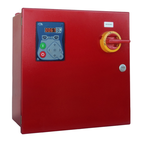
- Page 1 INSTALLATION AND MAINTENANCE MANUAL FOR JOCKEY PUMP CONTROLLERS...
- Page 2 Table of Contents 1. Introduction 2. Installation 3. Technical Documents JP-Manual-EN...
-
Page 3: Table Of Contents
Table of Contents ..........................4 Introduction ......................4 Types of Jockey Pump Controllers ..............4 Methods of starting/stopping ................5 ..........................6 Installation....................... 6 Preventive maintenance and test ................ 8 VISUAL INSPECTION ..................9 OPERATIONAL INSPECTION ................9 ..........................10 Technical Documents ................... -
Page 4: Introduction
Introduction Tornatech Jockey Pump Controllers are built to NEMA industrial standards and are UL listed. These controllers are intended for use with fire pump systems. Except in some cases, the controller is also seismic approved and has been tested in accordance with the ICC-ES AC156, IBC 2015 &... -
Page 5: Methods Of Starting/Stopping
This duplex jockey pump controller is designed to alternatively control two jockey pumps (lead & standby) for maintaining the designed water pressure in fire pump serviced systems and therefore prevent short cycling of the fire pump due to small leaks. The presence of a 100% standby jockey pump associated with a circuit that alternates lead &... -
Page 6: Installation
Installation Tornatech Jockey Pump Controllers are built to NEMA industrial standards and are UL listed. These controllers are intended for use with fire pump systems. Except in some cases, the controller is also seismic approved and has been tested in accordance with the ICC-ES AC156, IBC 2015 &... - Page 7 load and control terminal block points. Be sure to consult the appropriate field connection diagram included with the manual. Make all field connections to the remote alarm functions and any other optional features. AC POWER WIRING Connect the AC power. Check to see that all connections are both correctly wired and tight (see torque label). MOTOR WIRING Connect the motor cable.
-
Page 8: Preventive Maintenance And Test
• The LEFT button + the UP button is a shortcut to show the Timer-ON value when in NORMAL mode. • The LEFT button + the DOWN button is a shortcut to show the Timer-OFF value when in NORMAL mode. •... -
Page 9: Visual Inspection
VISUAL INSPECTION Inspect cleanliness of controller. Remove any object from the top of controller. Dust and clean the controller. Inspect controller for any evidence of corrosion outside. Inspect controller for any evidence of corrosion inside. Check for leaks on pressure transducer and piping. Inspect door for proper alignment and function of door locks Inspect tightness of all connections Inspect tightness of all terminal jumpers... -
Page 10: Technical Documents
Technical Documents...
Need help?
Do you have a question about the JP and is the answer not in the manual?
Questions and answers