
Related Manuals for Tornatech GPD


Summary of Contents for Tornatech GPD
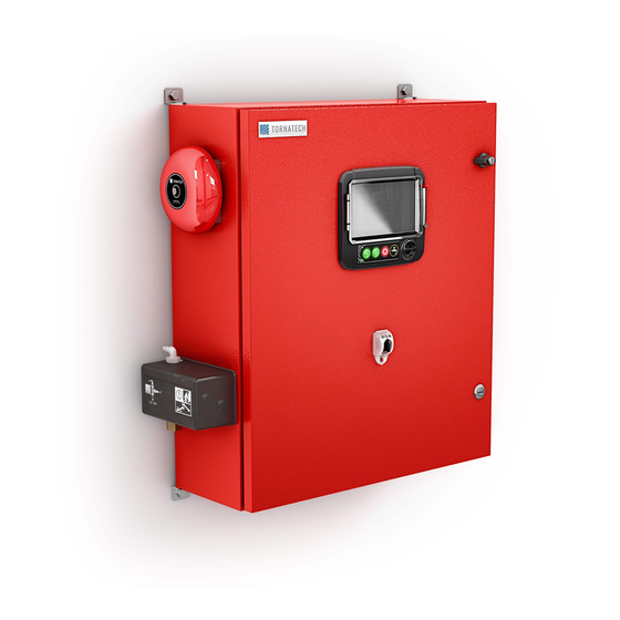
- Page 1 INSTALLATION AND MAINTENANCE MANUAL FOR DIESEL ENGINE FIRE PUMP CONTROLLERS MODEL GPD...
- Page 2 Table of Contents 1. Introduction 2. Installation 3. Main Features 4. Home 5. Alarms 6. Configuration 7. History 8. Service 9. Download Manuals 10. Language 11. Technical Documents GPDV2-Manual-EN v2.2.0.0...
-
Page 3: Table Of Contents
Table of Contents Introduction ..................................5 Types of Diesel Engine Fire Pump Controllers ......................5 Methods of Starting/Stopping ............................. 5 Installation ..................................7 FCC Regulations and Radio Standards Specification (RSS) Rules ................7 Location ..................................7 Mounting ..................................8 Storage ..................................8 Wiring and Connections ............................. - Page 4 Update Program Page ............................. 37 Factory Settings ............................... 38 Interlock Lockout ..............................38 Inputs..................................39 I/O Card Info ................................39 Network ..................................40 Reboot ViZiTouch ..............................40 History ................................... 41 History (Menu) ................................41 Events Page ................................42 Pressure Curves ..............................42 Power Curves ................................
-
Page 5: Introduction
The diesel engine fire pump controller includes two battery chargers to ensure the engine batteries are continuously charged. Types of Diesel Engine Fire Pump Controllers FIRE PUMP CATALOG NUMBER MODEL No. EXAMPLE: GPD-12-120 Model Prefix: GPD, GPDFM Battery Voltage: 12=12v, 24=24v Incoming Voltage: 120=110/120V 50/60Hz, 220=208/240V 50/60Hz... - Page 6 METHODS OF STOPPING MANUAL STOP Manual stop is done by pressing the STOP push button. Note that pressing the stop push button will stop the engine only if all starting causes have disappeared. AUTOMATIC STOP The automatic stop is possible only after an automatic start and this function has been activated. When this function is Enabled, the motor is automatically stopped 30 minutes (adjustable) after the restoration of the pressure (above the cut-out threshold) given that no other run cause is present.
-
Page 7: Installation
Installation This diesel controller is UL listed and FM certified. The controller is built in accordance with the latest edition of the National Fire Protection Association standard for the Installation of Centrifugal Fire Pumps, NFPA No.20 (Centrifugal Fire Pumps 2013 Edition). The controller is intended to be installed in accordance to NFPA 20-2013 in the USA National Electrical Code NFPA 70 In Canada Canadian Electrical Code, Part 1 Others * Local Electrical Codes *... -
Page 8: Mounting
The structural engineer of record on the project shall be responsible for anchorage details. Storage If the controller is not installed and energized immediately, Tornatech recommend following the instructions from the chapter 3 of the NEMA ICS 15 standard. -
Page 9: Energy Consumption
Energy Consumption Diesel Controller with boost charger Model / State 120VAC 220/240VAC VDC Output 12VDC / @ No charge 1.0A 1.0A 13.8V 12VDC / @ Full charge* 24VDC / @ No charge 1.0A 0.5A 27.6V 24VDC / @ Full charge** *12 amps through each battery **10 amps through each battery Incoming Power Connections... -
Page 10: Terminal Strip Descriptions
Terminal Strip Descriptions A-F : Alarm Output Terminals (DPDT Relay, 11/21:Common, 12/22:Normally Closed, 14/24:Normally Open): A: Controller Trouble (Fail safe) B: Engine Run C: Main SS in HAND/OFF position D: Engine Trouble E: Pump Room Alarm F: Optional Output 1 G-T : Field Input Terminal (Dry Contact Only: Voltage Free): G: Low Fuel Level (NO) -
Page 11: Quick Start-Up Guide
Quick Start-Up Guide The rating label is the most important label. It must be read carefully to ensure the compatibility between the controller and the installation. Verify that the controller is installed securely to the wall, or on the mounting stand (optional). Verify the Main Selector Switch is in the “OFF”... - Page 12 Open the controller's door and verify that the disconnect switch and all circuit breakers are in the “OFF” position. Verify and/or install the proper water connections for the water input and the drain. They must be securely installed and tightened. Refer to the silkscreen markings on the plastic cover.
- Page 13 Connect all cables between the engine control panel and the controller engine terminals (Identified as “U” on the IO board diagram displayed in the Terminal Strips Descriptions in the manual). Secure with the appropriate torque as indicated on the torque label and verify all connections. Connect the AC main line and ground to the AC terminal in the controller.
- Page 14 Once the controller has booted up, the “First Start Up” page appears. Press “User Login” and enter a valid authorization code. Once logged in, press “Power”. The “Power” page will automatically validate the power if no alarm is detected and if the power meets the requirements.
- Page 15 Press “Engine First Startup” and turn the Main Selector Switch to the “HAND” position. Note: Before starting the engine, verify that the engine has been officially commissioned (by an authorized engine representative or service dealer) and that the exhaust pipe is connected properly. Note: You can choose to skip this step completely by selecting “Skip engine validation step”.
- Page 16 Press “Pressure”. - Verify that the pressure reading on the screen matches with the calibrated pressure gauge installed on the sensing line. - Choose the desired units of measurement for pressure reading. - Adjust, if required, the range of the digital pressure gauge at Max. Pres. - Insert the Cut-Out and Cut-In pressure values of the fire pump.
- Page 17 From the “Home” page, verify that the displayed values are correct. Turn the “Main Selector Switch” to the “AUTO” position to activate the “Automatic” mode. This is the preferred position and from now on, the “Main Selector Switch” should always remain in that position.
- Page 18 The “First Start up” is now completed. The controller is fully installed and configured.
-
Page 19: Main Features
Main Features The ViZiTouch A: Power LED 3 colors: Pulsing green if the ViZiTouch is properly powered. B: Crank 1 button: Used to manually crank the starter from battery 1 while in "HAND" mode. C: Crank 2 button: Used to manually crank the starter from battery 2 while in "HAND" mode. D: Stop button: Used to stop the engine if all starting conditions are gone. -
Page 20: Vizitouch: Manual Rebooting Method
ViZiTouch: Manual Rebooting Method If required, here is the procedure to manually reboot the ViZiTouch: 1- Turn OFF all disconnecting means to de-energize the ViZiTouch. The ViZiTouch's screen should turn black. 2- Press the stop button or wait until the ViZiTouch's LED extinguishes. 3- Wait 10 seconds. -
Page 21: Home
Home Home (Menu) Home The home page displays all controller statuses and important values of the controller. This includes all voltages, currents, pressure, engine state and status, as well as all timers and cranking sequences. A- Navigation bar: Pressing this icon will open a navigation menu on the left side of the screen: 1- Go to Home page 2- Go to Alarms page 3- Go to Configuration page... - Page 22 Color of the box Lightning color Status Green Green Normal activities (bellow 2 amps) Green Yellow Charging (above 2 amps) Failure Grey Grey No AC voltage E: Alternative current status: Red when there is a failure and green otherwise. F: Ammeter: Displays the actual current between the charger and the battery in amps. G: The battery: The battery will be red if it is in failure and green otherwise.
-
Page 23: Screen Saver
Run test: Automatic motor starting is activated by the run test pushbutton. Alternating current failure: (Optional) Alternating current failure will count the time following an AC Failure and at the end of a predetermined time, will start the engine with an AC FAIL request. A red rectangular box will indicate the reason why the engine is not running despite the fact that a request is being made. -
Page 24: Alarms
Alarms Alarms (Menu) This page displays the list of currently active and occurred alarms. Alarms with adjustable parameters can be set in the Config ˃ Advanced ˃ Alarms pages (see section 6). An alarm is called ACTIVE when its triggering condition is still valid. An alarm is called OCCURRED when its triggering condition has been active, but is no longer true. - Page 25 - ECM Selector Switch in Alternate Position (301) - ECM Fault (304) - Engine Fuel Injection Malfunction (302) - PLD Low Suction Pressure (305) - High Raw Water Temperature (310) - Low Raw Water Flow (311) - Battery Failure 1-2 - DC Failure - Over Pressure Pump Room Trouble.
- Page 26 - Pressure Transducer fault detected: Occurs if the pressure reading is out of its normal range. Additionnally, if an optional dual pressure sensor is installed, it will be activated if the two pressure transducers show different readings. Further investigation is advised to determine what caused the different readings. Note that the controller will always choose the lowest pressure reading to determine the actual system pressure.
- Page 27 - Engine Overspeed*: Activates if the specific “Overspeed” input (3) is triggered on the engine connector strip and the engine is running. This alarm will immediately stop the engine and cannot be reset by using the reset button on the alarm page. The alarm must be reset on the engine itself and the controller must be turned OFF and ON with the HOA selector switch to complete the reset procedure for this alarm.
-
Page 28: Configuration
Configuration Config (Menu) Config The main configuration page is used to setup all basic configuration parameters and provides a quick means of changing the most common settings. There are seven (7) access parameter boxes; Pressure, Periodic Test, Run Test, Automatic Shutdown, Date & Time, Advanced and User Login. -
Page 29: Numpad Page
Advanced: Go to the advanced configuration pages. Date & Time Configuration: Select to display the Date Time page. NumPad Page The NumPad is activated every time the user presses on a white square box representing a number that can be set. -
Page 30: User Login Page / Keypad Page
changes. A dialog box will appear to confirm the change “Date and Time”. The user may cancel the changes by pressing the “Cancel” button. Please note that changing the date and time will have an effect on the logs chronology. The time zone can also be changed using the box in the bottom-right corner. -
Page 31: Advanced Configuration Page
Other KeyPads: The KeyPad is activated every time the user presses on a grey rectangle box with white text representing a text that can be set. The “X” button allows the user to cancel editing the value. The back arrow erases the last entered character. -
Page 32: Alarms
Run Period Timer This timer sets the time the engine will keep running after the demand is resolved. Time Range: 1-1440 Minutes Alarms Configuration > Advanced > Alarms Most alarms are not configurable in the field, but some are with the appropriate password level. If it's configurable, the checkboxes will be in white. -
Page 33: Chargers And Batteries
Silence Duration: Set the time this Alarm will remain silenced. Annunciate when occurred: Check this box to keep activated any associated relay even when this alarm has occurred. Acknowledgeable: Check this box to make the alarm acknowledgeable. If an alarm is ackowledged, the bell will be silenced and the alarm IO board Output will stop being active. -
Page 34: Starter Configuration
Charger boost health monitor enable: If checked, this feature will enable the monitoring of the chargers boost health. Charger boost health test interval: This is the minimum interval between two charger boost tests. Charger boost detection threshold: This is the minimum value the voltage has to raise during a boost test for the test to be consider as a success. - Page 35 Five analog sensors, an AC voltage sensor, two battery current sensors and two battery voltage sensors can be calibrated by accessing this page. The Analog Input 1 is dedicated to the Pressure Transducer. The other Analog Input depends on the controller options. Every sensor, except the AC Voltage can be calibrated the same way.
-
Page 36: Outputs
For the pressure transducer PT1, the low point (zero) is automatically acquired during first power up. It can be re- acquired by pressing the blue round arrow. The high point needs to be entered in order to calibrate the sensor. Outputs Config >... -
Page 37: Update Program Page
The first box from the top is used to change the name of the Output. For the output's logic, a combination of 5 digital inputs can be selected. Each input can be an alarm or a signal from a list and can be inverted by pressing the NO/NC contact symbol at the left of the screen. -
Page 38: Factory Settings
It is possible to reload a past configuration by pressing the "reload configuration" button. Dates with an "*" are settings following a "Service". Do not change a parameter on this page without previously consulting a Tornatech representant. Interlock Lockout Config > Advanced > Interlock Lockout This page is used to configure the Lockout input and the Interlock output parameters. -
Page 39: Inputs
-Enable in Remote: If checked, activation of the lockout input will prevent the Remote start. -Enable in Flow: If checked, activation of the lockout input will prevent the Flow start. Interlock is an Output that prevents a second engine from starting. -Engine Run Required: If enabled, the controller will wait to have Engine Run before putting Interlock active. -
Page 40: Network
Network Config > Advanced > Network This page displays the IP address, the Subnet Mask, the Default Gateway and the DNS1-2-3 of the controller. All those parameter can be changed manually by checking the box on the upper left corner. To apply the change, press on the blue arrow in the bottom right corner. -
Page 41: History
History History (Menu) History This page is used to access all data related to events, statistics, pressure history, power logs and the downloading of this information via one of the two USB ports. -Events: This button leads to the “Events” page, which displays the events from the most recent 500 logs. Each event log contains the date and time of occurrence as well as a brief description of the event. -
Page 42: Events Page
Events Page History > Events The Events Page shows the events from the last 500 logs which occurred in chronological order. The first column is the date, the second one is the time of occurrence and the third column is the “Event message”. To obtain a log that is older than thoses events, visit the “Saved Logs”. -
Page 43: Power Curves
This table allows viewing of the exact values used to generate the Pressure Curves with the precise time. Pressing the blue button on the top left corner will return to the graph page. Power Curves History > Power Curves On this page, a graphic of the “Battery 1 Voltage”, the “Battery 2 Voltage”, the “Battery 1 Current” and the “Battery 2 Current”... -
Page 44: Saved Logs
This table allows viewing of the exact values used to generate the Power Curves with the precise time. Press the blue button on the top left corner to return to the graph page. Saved Logs History > Saved Logs This page is used to access all past log files. Each log file is a CSV file containing the time, the date, the Cut-in, the Cut-out, the system pressure, the battery voltages and currents, the engine run signal, the jockey pump run signal and the log event message. -
Page 45: Pump Curves
The logs are arranged chronologically. To select the displayed data, press on the filter icon in the top center of the screen. From this page, the selected values will be displayed. Press on “Log File” at the top left of the screen to go back to the logs table. -
Page 46: Statistic
Statistic History > Statistics This page leads to 3 other Statistics pages: “All Time Statistics”, “First Service Statistics” and “Last Service Statistics”. All Time Statistics History > Statistics > All Time Statistics The “All Time Statistics” contains two parameters: - Since: The date the controller has been powered for the first time. - On Time: The amount of time the controller has been On for. -
Page 47: First Service Statistics
First Service Statistics History > Statistics > First Service Statistics This page allows the user to view the “First Setup Statistics”. The parameters are: From: - Since: Date of the first setup - On Time: Time the controller spent On, in DAYS-HOURS:MINUTES-SECONDS Engine: - On Time: Time the engine spent On, in DAYS-HOURS:MINUTES-SECONDS - Start Count: Number of times the engine has started... -
Page 48: Last Service Statistics
Last Service Statistics History > Statistics > Last Service Statistics This page allows the user to view the “Last Setup Statistics”. The parameters are the same as the ones from the “First Setup Statistics” page but from the “Last Service”. Download History >... -
Page 49: Service
The “Nameplate Information” page contains all the information found on the nameplate. The Jockey Pump Cut-Out and Cut-In can be set on this page. It is possible to install a custom Service card on this page. Contact Tornatech for more information. -
Page 50: Download Manuals
Download Manuals Pressing on the question mark will redirect to the download page. A pdf version of the manual can be downloaded on an USB device. -
Page 51: Language
Language The language displayed on the ViZiTouch can be selected on this page. -
Page 52: Technical Documents
Technical Documents How to Test: Charger 1 Fail Unpower the charger 1 by putting the circuit breaker in the off position. Charger 2 Fail Unpower the charger 2 by putting the circuit breaker in the off position. DC Failure Switch Circuit Breaker 3 (CB3) and Circuit Breaker 4 (CB4) in Off position or disconnect #6 and #8 engine wires (See drawing for more details). - Page 53 High Water Level Put a jumper between High Water Level input and ground (See drawing for more details). Water Reservoir Low Put a jumper between Water Reservoir Low input and ground (See drawing for more details). Pump Room Alarm To activate this common alarm, at least one of the following alarms must be active: Low Fuel Level, High Fuel Level, Fuel Tank Leak, AC Fail, Low Ambient Temperature, High Ambient Temperature, Low Suction Pressure, Water Reservoir Empty, High Water Level or Water Reservoir Low.
- Page 54 Battery 2 Overvoltage You need to be logged in to modify these settings. Go to Config>Advanced> Alarms>Battery2Overvoltage. Change the Overvoltage Battery 2 setpoint to the minimum allowable. Loss of Continuity 1 Disconnect #9 engine wire (See drawing for more details). Wait 1-2 minutes. Loss of Continuity 2 Disconnect #10 engine wire (See drawing for more details).
- Page 55 IO Expansion 3 Communication Error Press the Reset button of the Expansion 3 IO Board (Small button close to the phone jack) IO Expansion 4 Communication Error Press the Reset button of the Expansion 4 IO Board (Small button close to the phone jack) Low Pump Room Temperature Put a jumper between Low Pump Room Temperature input and ground (See drawing for more details).
- Page 56 TORNATECH MODEL GPD DIESEL FIRE PUMP CONTROLLER PRE- FIELD ACCEPTANCE TEST CHECK LIST Note: This document should be an official indication of whether or not the installation and general condition of the equipment is adequate for a field acceptance test. This document should also aid the individual responsible for executing the field acceptance test to decide whether or not to carry out the field acceptance test of the equipment.
- Page 57 Tornatech Controller S/N: _________________________________________ Installation address: _________________________________________ _________________________________________ _________________________________________ Check list completed? _____________Yes _____________ No Check list completed by: __________________________________________ Company: __________________________________________ Date: __________________________________________ Witnessed By: __________________________________________ Comments: ___________________________________________________________________________ ___________________________________________________________________________ ___________________________________________________________________________ ___________________________________________________________________________ ___________________________________________________________________________ ___________________________________________________________________________...
- Page 58 DIESEL ENGINE FIRE PUMP CONTROLLER FIELD ACCEPTANCE TEST REPORT Note: This document is the Tornatech official Field Acceptance Test report which follows the latest NFPA 20 requirements of article 14.2.6 Controller Acceptance Test pertinent to diesel engine driven fire pump controllers.
- Page 59 - If the engine was started automatically, a visual and audible alarm will be present and the engine will not shutdown. To shutdown, turn the selector switch to the OFF position. - Note: Please remove the jumpers and reset the alarm in order to continue to the next simulation.
- Page 60 Engine Trouble connected? _____Yes _____ No Controller Trouble connected? _____Yes _____ No Other contacts supplied and connected? Yes: _______________________________________________________ No: _____ Tornatech Controller S/N: _________________________________________ Installation address: _________________________________________ _________________________________________ Field Acceptance Test completed? _____Yes _____ No Field Acceptance completed by: __________________________________________...
Need help?
Do you have a question about the GPD and is the answer not in the manual?
Questions and answers