
Related Manuals for Tornatech VPX


Summary of Contents for Tornatech VPX
- Page 1 INSTALLATION AND MAINTENANCE MANUAL FOR VARIABLE SPEED ELECTRIC FIRE PUMP CONTROLLERS MODEL VPX+VPU V2024.02...
-
Page 2: Table Of Contents
TABLE OF CONTENTS Important Safety Information Introduction Technical Data Installation Storage Seismic Environment Electromagnetic compatibility (EMC) Handling FCC Regulations and Radio Standards Specification (RSS) Rules Location Mounting Floor mounting Wall mounting Making System Pressure Connections Making Electrical Connections Important Precautions Procedure Operator interface Methods of starting and stopping Variable Speed Electric Fire Pump mode switch VFD mode Bypass mode Methods of starting Automatic start Manual start Remote manual start Remote automatic start, deluge valve start Emergency start V2024.02... - Page 3 Sequential start Test start Methods of stopping Manual stop Automatic stop Emergency stop Transfer switch operation sequence Transfer to alternate power source Re-transfer to normal power source Test transfer sequence Manual operation Commissioning VFD Reforming procedure VFD Settings Graphic display terminal Motor parameters Basic parameters Autotune Procedure Maintenance Patents V2024.02...
-
Page 4: Important Safety Information
IMPORTANT SAFETY INFORMATION Warning: This product can expose you to chemicals including DINP, which is known to the State of Cali- fornia to cause cancer, and DIDP which is known to the State of California to cause birth defects or other reproductive harm. Warning: This product can expose you to chemicals including lead and lead compounds, which are know to the State of California to cause cancer and birth defects or other reproductive harm. - Page 5 Always verify that no voltage is present before proceeding and always follow generally accepted safety procedures. Controller disconnect switch must be in the “off” position in order to open the enclosure door. Tornatech cannot be liable for any misapplication or incor- rect installation of its products.
-
Page 6: Introduction
INTRODUCTION Variable Speed Electric Fire Pump controllers are designed to start an electric motor driven fire pump. It is equipped with a Variable Frequency Drive (VFD) that will regulate the motor speed, by controlling the frequency applied to the motor, in order to maintain a certain set-point pressure. It can either start the fire pump manually through the local start pushbutton or automatically through the sensing of a pres- sure drop in the sprinkler system. The fire pump controller is supplied with a pressure transducer. The fire pump can be stopped manually with the local stop pushbutton or automatically after the expiration of a field programmable timer. It is equipped with an automatic transfer switch that feeds the controller from either the normal or the alternate power source. TECHNICAL DATA Rating Value Rated Operational Current Ie According to the Motor (HP/kW) Rated Operational Voltage Ue According to the controller rating label Rated Operational Frequency 50/60Hz Standard environmental temperature 4°C to 40°C Altitude ≤ 2000m Relative humidity 5% to 80% Pollution degree Short Circuit Current Rating Icc (SCCR) (A) According to the controller rating label Standard degree of protection NEMA Type 12 Standby power consumption 200 W V2024.02... -
Page 7: Installation
INSTALLATION STORAGE If the controller is not installed and energized immediately, Tornatech recommends following the instructions in chapter 3 of NEMA ICS 15. SEISMIC Variable Speed Electric Fire Pump controllers are optionally seismic approved and has been tested in accordance with the ICC-ES AC156, IBC 2015 & CBC 2013 standards. Proper installation, anchoring and mounting is required to validate this compliance report. Refer to this manual and drawings to determine the seismic mounting requirements and location of the center of gravity (you may need to contact fact- ory). The equipment manufacturer is not responsible for the specification and performance of anchor- age systems. The structural engineer of record on the project shall be responsible for anchorage details. The equipment installation contractor shall be responsible for ensuring the requirements specified by the structural engineer of record are satisfied. If detailed seismic installation calculations are required, please contact the manufacturer for the performance of this work. ENVIRONMENT Variable Speed Electric Fire Pump controllers are intended to be installed in locations where ambient temperatures are within 4°C and 40°C and the relative humidity is controlled between 5% and 80%. They are intended for pollution degree 3 and shall be installed at an altitude of no more than 2000 meters. For abnormal installation environment, consult factory. ELECTROMAGNETIC COMPATIBILITY (EMC) Variable Speed Electric Fire Pump controllers have been tested for the most stringent conditions for emissions (Environment B) and immunity (Environment A), hence controllers can be installed in either environment. All controllers variants share the same electronics and comply to those criteria without requiring additional measures. HANDLING The weight of each Variable Speed Electric Fire Pump controller is indicated on the packing label. Light- weight controllers do not require special handling instructions, while heavy controllers are equipped with lifting means and should be handled following the guidelines specified in Tornatech's document "Large Enclosure Safe Handling Requirements_PN12162021". FCC REGULATIONS AND RADIO STANDARDS SPECIFICATION (RSS) RULES To comply with FCC and Industry Canada RF exposure compliance requirements, a separation distance ... -
Page 8: Location
This device contains licence-exempt transmitter(s)/receiver(s) that comply with Innovation, Science and Economic Development Canada’s licence-exempt RSS(s). Operation is subject to the following two con- ditions: 1. This device may not cause interference. 2. This device must accept any interference, including interference that may cause undesired oper- ation of the device. Compliance: CAN ICES-003(B) / NMB-003(B) This device complies with part 15 of the FCC Rules. Operation is subject to the following two conditions: (1) This device may not cause harmful interference, and (2) this device must accept any interference received, including interference that may cause undesired operation. Note: This equipment has been tested and found to comply with the limits for a Class A digital device, pursuant to part 15 of the FCC Rules. These limits are designed to provide reasonable protection against harmful interference when the equipment is operated in a commercial environment. This equipment generates, uses, and can radiate radio frequency energy and, if not installed and used in accordance with the instruction manual, may cause harmful interference to radio communications. Operation of this equipment in a residential area is likely to cause harmful interference in which case the user will be required to correct the interference at his own expense. “Changes or modifications not expressly approved by the party responsible for compliance could void the user's authority to operate the equipment.” LOCATION Consult the appropriate job plans to determine the controller mounting location. The controller shall be located as close as practical to the engine or motor it controls and shall be within sight of the engine or motor. The controller shall be located or protected such that it will not be dam- aged by water escaping from pump or pump connections. Current carrying parts of the controller shall be not less than 12 in. (305 mm) above the floor level. Working clearances around controller shall comply with NFPA 70, National Electrical Code, Article 110 or C22.1, Canadian Electrical Code, Article 26.302 or any applicable local codes. The standard controller enclosure is rated NEMA Type 12. It is the installer’s responsibility to insure that either the standard enclosure meets the ambient conditions or that an enclosure with an appropriate ... -
Page 9: Floor Mounting
FLOOR MOUNTING Floor mounted controllers shall be attached to the floor using all holes provided on the mounting feet with hardware designed to support the weight of the controller. The mounting feet provide the neces- sary 12 in. (305 mm) clearance for current carrying parts. WALL MOUNTING Refer to the controller dimension drawing for necessary mounting dimensions. The controller is wall mounted by using at least four (4) wall anchors, 2 anchors for the top mounting brackets and 2 anchors for the bottom mounting brackets. The brackets are dimensionally on the same centerline for ease in mounting. There should be a clearance of at least 6 inches (152mm) around the controller to allow proper air circulation around the equipment. 1. Using either the dimension print or by measuring the distance between the center lines of the lower bracket slots, transcribe this dimension on to the wall. Note: The bottom edge of the enclos- ure should be a minimum of 12” (305mm.) from the floor in case flooding of the pump room occurs. 2. Drill and put anchors into the wall for the lower mounting brackets. 3. Mark on the wall, the location of the holes in the upper mounting brackets. 4. Drill and put anchors into wall for the upper mounting brackets. 5. Install bolts and washers in lower anchors. 6. Align holes in upper mounting brackets and install bolts and washers in anchors. 7. Shim anchors as necessary to ensure rear of enclosure is vertical level and enclosure is not stressed. 8. Tighten all anchor bolts. 9. ... -
Page 10: Important Precautions
Failure to do so may cause injuries to personnel, damage the controller and subsequently void warranty. Prior to making any field connections 1. Open door of enclosure and inspect internal components and wiring for any signs of frayed or loose wires or other visible damage. 2. Verify that the controller information is what is required on the project: 1. Tornatech catalog number 2. Motor electrical nameplate information matches controller rating for voltage, frequency, FLA and HP. 3. Project's electrical contractor must supply all necessary wiring for field connections in accordance with the National Electrical Code, local electrical code and any other authority having jurisdiction. 4. Refer to the appropriate field connection drawing for wiring information. - Page 11 9. Check to see that all connections are both correctly wired (in accordance with the field con- nection diagram) and tight. 10. Close the enclosure door. V2024.02...
-
Page 12: Operator Interface
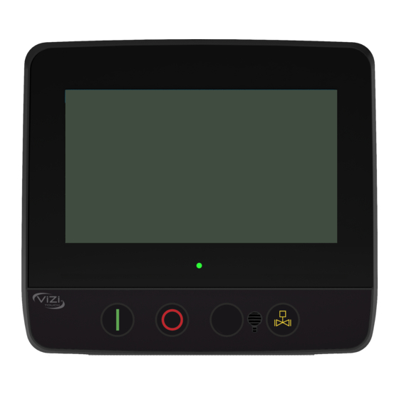
OPERATOR INTERFACE A. Status LED B. Manual start C. Stop D. Transfer-switch test E. Run test F. Alarm buzzer G. Touch screen display H. Factory reserved I. USB key connector for logs download and software updates J. Ethernet connector for standard TCP/IP communication V2024.02... -
Page 13: Methods Of Starting And Stopping
METHODS OF STARTING AND STOPPING VARIABLE SPEED ELECTRIC FIRE PUMP MODE SWITCH The VPX+VPU is equipped with a VFD mode switch that is located under the Vizitouch. It is protected by a lockable cover, and has 2 positions; VFD and BYPASS. If the mode switch changes position while the motor is running, the motor will stop and restart in the new m ode VFD MODE This is the normal mode of operation. The controller will use the VFD as the primary starting means, and automatically switch to the bypass starting means in case of a VFD alarm. Once the controller has auto- matically switched to the bypass starting means, it will remain in this state until the VFD alarms are manually reset. Note: When the motor is driven by the VFD, it may run at minimum speed when the system pressure is above the set point pressure. -
Page 14: Sequential Start
SEQUENTIAL START In case of a multiple pump application, it may be necessary to delay the automatic starting of each motor to prevent simultaneous starting of all motors. TEST START The motor can be started in test mode manually by pressing the run test pushbutton, or automatically by using the periodic test feature. METHODS OF STOPPING MANUAL STOP Manual stop is done by pressing the priority stop pushbutton. Note that pressing the stop push button will prevent the motor from restarting as long as the button is pressed, plus a two second delay. This action has priority over any active demand, but the motor will restart automatically once the button is released if there is any. AUTOMATIC STOP This function is never activated by default and must be authorized by the authority having jurisdiction prior to activating. Automatic stop is possible only after an automatic start. W hen this function is enabled, the motor is automatically stopped 10 minutes after the restoration of the pressure ... -
Page 15: Transfer Switch Operation Sequence
TRANSFER SWITCH OPERATION SEQUENCE The transfer-switch shall be supplied either by a second utility or by an on-site standby generator com- plying with the requirements of a Level 1, Type 10, Class X system of NFPA 110, meaning it shall supply power to the fire pump controller within 10 seconds. Additionally, the fire pump controller shall be fully operational and ready to start within 10 seconds after the application of power. Those two requirements combined means that the total time frame between a normal power loss and a the controller being ready to start on the alternate power, if provided by a generator, shall be at most 20 seconds. TRANSFER TO ALTERNATE POWER SOURCE When the normal power source is outside acceptable parameters for at least three seconds, a generator start command is issued. The three second delay can be adjusted to help meet the 10 seconds require- ment of the generator, but doing so increases the risk of nuisance starting of the generator in case of power brownouts. Special consideration must be taken before editing this value. Once the alternate power is within acceptable parameters for at least another three seconds, the trans- fer to the alternate power source is initiated. RE-TRANSFER TO NORMAL POWER SOURCE The transfer switch will stay in alternate position, if the motor is running, for as long as the alternate power source is within acceptable parameters. - Page 16 5. Turn the handle clockwise 180° to transfer from Alternate to Normal position, or coun- terclockwise 180° to transfer from Normal to Alternate position. 6. Remove the handle and put it back on the support inside the controller door. 7. If required, pull the emergency start handle and lock it in place. 8. Close the door and using the disconnecting switch handles put back the power on both sides. BE CAREFUL Do not close the controller door if the handle is still installed in the Transfer Switch. Do not operate manually the Transfer Switch if the power is still ON. V2024.02...
-
Page 17: Commissioning
COMMISSIONING Only an authorized field acceptance provider shall proceed with Variable Speed Electric Fire Pump controller commissioning. If you do not have the required training and authorization, contact factory. Until commissioning is completed, the controller main screen is replaced by the commissioning menu and the automatic mode is disabled. VFD REFORMING Reforming a VFD is the action of applying voltage to the VFD power path without running a motor. If the drive was not connected to a voltage source for an extended period of time, the capacitors must be restored to their full performance before the motor is started, otherwise the VFD may be damaged. If the VFD has not been started for a year or more, a VFD Reforming Required warning will be issued and the controller will automatically start in bypass until the reforming is done. Proper controller main- tenance as per this document will prevent reforming from being required under normal conditions. -
Page 18: Basic Parameters
7. Max frequency Should be set to the nominal motor frequency. BASIC PARAMETERS Continue on the Simply Start menu and modify or validate the next parameters: 1. Acceleration ramp time 2. Deceleration ramp time 3. Low speed 4. High speed Refer to the VFD Parameters List for the factory settings values. AUTOTUNE The autotune procedure allows the VFD to acquire electrical motor characteristics and enhance the VFD performance. It is recommended to perform the autotune only once during the first startup. Perform the autotune on a stopped and cold motor as heat can influence the tuning result. While doing the Autotune the VFD will scan the motor and acquire information about the motor. Before starting the Autotune on the VFD, read the whole procedure. Then perform step by step. 1. Place the Mode switch on the VFD position. 2. On the Vizitouch. Enter a level 2 password. 3. Go to the VFD Config page and press the VFD Autotune button. The VPx will close the VFD isol- ating contactors. This will energize the VFD power path and allow it to be connected to the motor. The VFD isolating contactors will remain closed for 3 minutes. During that time, you can perform the Autotune on the VFD display. 4. On the VFD Graphic Display Terminal, go to the Simply Start menu 5. Go to the Autotuning parameter and press OK to enter the Autotuning page. 6. Select Apply Autotuning and press OK. V2024.02... -
Page 19: Procedure
To commission the controller: 1. Secure the door in closed position then put the circuit breaker disconnecting means in ON pos- ition. 2. Log in with your password and complete the first start up menu on the screen. 3. Make sure the procedure is completed with the VFD set to constant speed mode. 4. For three-phase motors, in case of incorrect rotation on the bypass starting means, power off the controller and swap two wires at the contactor load side, then power the controller back on. 5. In case of incorrect motor rotation on the VFD starting means, go on the graphical display ter- minal and change the Output phase rotation PHr parameter on the Complete settings > Motor parameter > Motor Control menu. 6. Once all the necessary steps are completed and that you are logged in with your password, the "Service Done" button will become online. 7. Press the "Service Done" button once you are satisfied with the readings and parameters. 8. Download the logs to save in your report. 9. To finalize the controller commissioning, it is important to refer to the VPx Complete Setup pro- cedure to adjust the advanced parameters of the VFD. This will assure the VFD response correctly and in a timely manner to a pressure drop. V2024.02... -
Page 20: Maintenance
MAINTENANCE Tornatech controllers are covered by a l imited warranty and backed by a 10-years service life or until supply last, provided that proper installation, commissioning, use and maintenance of the controller is made as per this document, NFPA 25, and any maintenance standard applicable. Proper controller performance must be asserted at least once a month by executing the following: 1. With the system being at nominal pressure, ensure that the pressure reading is within tolerances 2. Perform a test start sequence on both the VFD and the bypass starting means and verify that 1. The motor starts when the pressure falls below cut-in 2. There are no alarms 3. There is no nuisance tripping 4. The motor starts properly and is able to accelerate within the expected time 5. The motor rotates in the appropriate direction 6. The pump is able to rise the pressure above the cut-out 7. The motor stops when the pressure is above cut-out after the configured test duration time In addition to the above, the following preventative maintenance must be performed at least once year: 1. Turn off the controller 2. Do a visual inspection of the exterior of the controller 3. Open the enclosure and do a visual inspection of the interior of the controller 4. Make sure that there is no dust accumulation inside the controller 5. Clean the fans and air outlet filters from dust accumulation 6. Inspect the tightness of each dead cable 7. Put the controller back in service... -
Page 21: Patents
PATENTS Country Title Grant NO Mechanical activator for contactor 2741881 Mechanical activator for contactor US8399788B2 Mechanical activator for electrical contactor 165512 Mechanical activator for electrical contactor 165514 Mechanical activator for electrical contactor D803794 Mechanical activator for electrical contactor Patent pending Mechanical activator for electrical contactor 002955393-0001/2 Mechanical activator for electrical contactor Patent pending Mechanical activator for electrical contactor Patent pending Fire pump digital operator 163254 Fire pump digital operator interface D770313 Fire pump digital operator interface Patent pending Fire pump digital operator interface 002937250-0001 System and method for detecting failure in a pressure Patent pending sensor of a fire pump system System and method for detecting failure in a pressure Patent pending sensor of a fire pump system V2024.02... - Page 22 AMERICAS Tornatech Inc. Head Office Laval, Quebec, Canada Tel.: +1 514 334 0523 Toll free: +1 800 363 8448 EUROPE Tornatech Europe SA Mont-Saint-Gilbert, Belgium Tel.: +32(0)10 84 40 01 MIDDLE EAST Tornatech FZE Dubai, United Arab Emirates Tel.: +971(0)4 887 0615 ASIA Tornatech Pte Ltd. Singapore Tel.: +65 6795 8114 Tel.: +65 6795 7823 FOLLOW US www.tornatech.com V2024.02...
Need help?
Do you have a question about the VPX and is the answer not in the manual?
Questions and answers