
Related Manuals for Tornatech GFD


Summary of Contents for Tornatech GFD
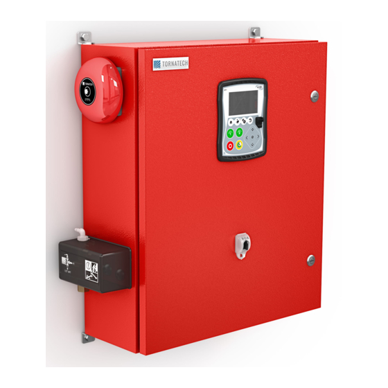
- Page 1 INSTALLATION AND MAINTENANCE MANUAL FOR DIESEL ENGINE FIRE PUMP CONTROLLERS MODEL GFD...
- Page 2 Table of Contents 1. Introduction 2. Installation 3. Main Features 4. Home 5. Alarms 6. Configuration 7. History 8. Technical Documents GFD-Manual-EN v1.4.0.0...
-
Page 3: Table Of Contents
Table of Contents Introduction ..................................5 Types of Diesel Engine Fire Pump Controllers ......................5 Methods of Starting/Stopping ............................. 5 Installation ..................................7 Location ..................................7 Mounting ..................................7 Storage ..................................7 Wiring and Connections ............................. 7 Water Connections ..............................7 Electrical Wiring ................................. - Page 4 The Sensors Pages ..............................38 Interlock Lockout ..............................41 History ................................... 43 History (Membrane button) ............................43 Details of the History Page ............................44 Events Page ................................44 Download to USB Device ............................44 The Statistics ................................46 All Time Statistics ..............................46 Pressure Curves ..............................
-
Page 5: Introduction
The diesel engine fire pump controller includes two battery chargers to ensure the engine batteries are continuously charged. Types of Diesel Engine Fire Pump Controllers FIRE PUMP CATALOG NUMBER MODEL No. EXAMPLE: GFD-12-120 Model Prefix: GFD Battery Voltage: 12=12V, 24=24V Incoming Voltage: 120=110/120V 50/60Hz, 220=208/240V 50/60Hz... - Page 6 METHODS OF STOPPING MANUAL STOP Manual stop is done by pressing the STOP push button. Note that pressing the stop push button will stop the engine only if all starting causes have disappeared. AUTOMATIC STOP The automatic stop is possible only after an automatic start and this function has been activated. When this function is Enabled, the motor is automatically stopped 30 minutes (adjustable) after the restoration of the pressure (above the cut-out threshold) given that no other run cause is present.
-
Page 7: Installation
The mounting feet provide the necessary 12 in. (305 mm) clearance for current carrying parts. Storage If the controller is not installed and energized immediately, Tornatech recommend following the instructions from the chapter 3 of the NEMA ICS 15 standard. Wiring and Connections... -
Page 8: Electrical Wiring
Electrical Wiring The electrical wiring between the power source and the diesel engine fire pump controller shall meet the NFPA 20, Chapter 12.3.5.1, 12.3.5.2 and 12.2.5.3, NFPA 70 National Electrical Code Article 695 or C22.1 Canadian Electrical Code, Section 32-200 or other local codes. Electrical Connections A licensed electrician must supervise the electrical connections. -
Page 9: Terminal Strip Descriptions
Terminal Strip Descriptions A-F : Alarm Output Terminals (DPDT Relay, 11/21:Common, 12/22:Normally Closed, 14/24:Normally Open): A: Controller Trouble (Fail safe) B: Engine Run C: Main SS in HAND/OFF position D: Engine Trouble E: Pump Room Alarm F: Optional Output 1 G-T : Field Input Terminal (Dry Contact Only: Voltage Free): G: Low Fuel Level (NO) -
Page 10: Quick Start-Up Guide
Quick Start-Up Guide The rating label is the most important label. It must be read carefully to ensure the compatibility between the controller and the installation. Verify that the controller is installed securely to the wall, or on the mounting stand (optional). Verify the Main Selector Switch is in the “OFF”... - Page 11 Open the controller’s door and verify all circuit breakers are in the lower “OFF” position. Verify and/or install the proper water connections for the water input and the drain. They must be securely installed and tightened. Refer to the silkscreen markings on the plastic cover.
- Page 12 Connect all engine cables between the control panel and the controller engine terminals (Identified as “S” on the IO board diagram that is displayed in the Terminal Strip Descriptions in the manual). Secure with the appropriate torque as indicated on the torque label and verify all connections. Connect the AC main lines and ground to the AC terminals in the controller.
- Page 13 The “First Setup” page replaces the Homepage until the “First Setup” is done. Verify that the controller reads the batteries voltage and current. Verify the “AC” is “OK” and not “FAIL”. Verify that the pressure reading is correct. Turn the Main Selector Switch in the “HAND” position.
- Page 14 Before trying to start the engine, verify that the engine setup is complete and the exhaust pipe is connected properly. Start the engine manually by using the “Crank 1” membrane button. Verify that the engine has started and is running properly. Stop the engine by turning the “Main Selector Switch”...
- Page 15 Click on the “Go to Setup” button. The “Config” page is now visible. Click on the “padlock” button to log in with your password. If needed, read the “User Login / KeyPad” section for more information on how to enter your password. Once a valid password is confirmed, the “Config”...
- Page 16 When satisfied with the controller settings, press the "Home" button on the membrane, acknowledge the changes by pressing the done button. If the done button is unavailable, ensure that a sufficient authorization code has been entered. Proceed with the download step to save the report.
- Page 17 Press the home page button to verify that the displayed values are correct. Turn the “Main Selector Switch” to the “AUTO” position to activate the “Automatic” mode. This is the preferred position and from now on, the “Main Selector Switch” should always remain in that position.
- Page 18 The “First Start up” is now completed. The controller is fully installed and configured.
-
Page 19: Main Features
Main Features The ViZiTouch A: Power LED: Indicates if the ViZiTouch is properly powered. B: Touch Screen: 4.2 inches color touch screen LCD. C: Alarm LED: Indicates if an alarm is currently active. D: Front USB Connector: USB Device connector used for file download, software updates, service reports. E: Home button: Used to navigate to the Home page. -
Page 20: Alarm Bell
Alarm Bell The alarm bell is activated under default faulty conditions and under optional or user defined conditions. Any of these conditions will energize the alarm bell but may be silenced, except in some cases, by pressing on the “Alarms / silence” membrane button. When silenced, the alarm bell restarts ringing if a new fault occurs or if the alarm conditions remain unchanged after 24 hours. -
Page 21: Home
Home Home (Membrane button) Home The home page displays all controller statuses and important values of the controller. All voltages, currents, pressure, engine state and status, as well as all timers and cranking sequences. The entire background will become red if an alarm becomes active. This feature will help the user identify a problem even at a significant distance away from the controller. - Page 22 sequence. It will stay on a step during the 15 seconds of wait and on the 15 seconds of cranking and then will count on until the sixth step, which is the end of the cranking sequence. E: Diesel engine. It will be grey if the engine is stopped, green if an “Engine Run” signal is detected and red if an “Overspeed”...
-
Page 23: Screen Saver
represents the Cut-Out set point. These values will also be represented by a red and a green lines on the gage, allowing a quick comparison between the actual pressure and the set points. At the bottom of the gauge, a digital indicator shows the actual discharge pressure represented also by the needle of the gauge. -
Page 24: Alarms
Alarms Alarms (Membrane button) Alarms Displays the list of currently active and occurred alarms. An alarm is called ACTIVE when its triggering condition is present. An alarm is called OCCURED when its triggering condition has been active, but is no longer true. Alarms with an "*"... - Page 25 - Battery Failure 1-2 - DC Failure - Over Pressure Pump Room Trouble: A common alarm activated when the following events occur: - Fuel Tank Leak - Low Fuel Level - High Fuel Level - AC Failure - Low Pump Room Temperature - Low Suction Pressure - Water Reservoir Low - Water Reservoir Empty...
- Page 26 - PT fault detected: If an optional dual pressure sensor is installed, it will be activated if the two pressure transducers show different readings. Further investigation is advised to determine what caused the different readings. Note that the controller will always choose the lowest pressure reading to determine the actual system pressure.
- Page 27 - Engine Low Oil Pressure: Activates if the specific “Low Oil Pressure” input is triggered on the engine connector strip and the engine is running. This alarm will stop the engine only if triggered during a manual run test or a weekly test.
-
Page 28: Configuration
Configuration Config (Membrane button) Config Setup all basic configuration parameters. The main configuration page provides a quick means of changing the most common settings. The padlock icon indicates the current authorization level. A locked padlock indicates that only basic settings can be changed. Press on the padlock to enter an authorization code to unlock additional settings. -
Page 29: Numpad Page
Inside the lower box, the Automatic Shutdown may be activated and the duration of the “Run Period Timer” is shown. To edit the “Run Period Timer”, refer to the “Timers” page in the advanced configuration pages. NumPad Page The NumPad is activated every time the user clicks on a white square box representing a number that can be set. On top of the NumPad, the current parameter is shown. -
Page 30: User Login Page / Keypad Page
The Date and Time can be configured by selecting the current month and year by pressing the arrow buttons on each side of the “Month-Year” display and selecting the day of the month by selecting the actual day. The time is set by pressing the two square boxes under the clock;... -
Page 31: Advanced Configuration Page
character and the "CA" button clears the whole text field. Simply click the "OK" button once the value is set. This type of text field is mostly used to generate a digital text indication for a custom alarm input. Advanced Configuration Page Config >... - Page 32 calibration of the battery chargers in the “power supply” mode. To do so, simply turn the batteries circuit breaker to OFF. This page is used to calibrate all analog currents. The first number right beside the Battery 1 and Battery 2 text shows the actual current reading.
-
Page 33: Timers Page
Voltage Coast Drop Detection Enable : If enable, this second condition on the battery test is activated. On smaller battery, the rise in current during a boost test might be to small to have a conclusive test. This second test verify the capacitive effect on the battery line after a boost sequence. -
Page 34: Inputs/Outputs Configuration
Inputs/Outputs Configuration Config > Advanced > IO Diesel Input Selection - Config - Output Config This page, if logged in, allows the re-assignation of 3 programmable inputs by pressing on the signal name. If the Deluge Valve signal is selected, it will be assigned as a normally closed input. Proceed with caution as this may cause the engine to start. -
Page 35: Inputs/Outputs Expansion Board 1-2-3-4
This page allows the configuration of alarm signals on the inputs, and outputs relay signals. Two buttons located far right navigates between the input and output section of the page. Input: The input page has four elements: The NO/NC setting, the “Digital Text Indication” field, the “Alarm Bell Icon” and the “Alarm Icon”. -
Page 36: Update Program Page
This page allows the configuration of both programmable inputs and outputs available on an IO Expansion board. Two buttons located far right navigates between the input and output section of the page. Input: The input page has four elements: The NO/NC setting, the "Digital Text Indication" field, the "Alarm Bell Icon" and the "Alarm Icon". -
Page 37: Factory Settings
Factory Settings Config > Advanced > Factory Settings The factory settings are always pre-configured at the factory and set the main parameters of the controller. Left Section: Automatic Controller – Non-Automatic Controller: An automatic controller will respond to automatic start requests, like a pressure drop announced by a pressure transducer or a pressure switch, a deluge valve signal or a remote automatic start trigger. -
Page 38: Reset To Factory Settings Page
“Factory Reset”. Its purpose is to allow an update of configuration variables that can only be updated by Tornatech Inc. All other square buttons on this page are “Level 9” security and can only be used by certified Tornatech representatives, unless otherwise specified. The first square in the upper left corner performs the “Select all”... - Page 39 In the ViZiTouch, all sensors refer to analog input connectors on the I/O board. They all have similar settings and configuration. The “Installed” selection (”Level 2” security): Install or uninstall this sensor from the ViZiTouch configuration. Discharge Pressure: To set the pressure system unit, go the “Config” page. All pressure transducers share the same unit.
- Page 40 Water Level: The “Water Level” sensor shares the same analog input (AI4) as the suction pressure sensor. Only one of them can be installed at all time. Prior to installing one of them, the other one must be uninstalled by visiting its own sensor page.
-
Page 41: Interlock Lockout
- Enable/Disable the corresponding alarm/warning condition by pressing the square button. - Alarm Bell Icon: Activates the bell when the condition occurs. - Alarm Icon: If selected, the occurring condition will be an alarm. If unselected, it will be a simple warning. - RESET: Value at which the condition will go from the “ACTIVE”... - Page 42 - Enable in Remote Manual mode: If checked, this option will activate the output "interlock" on a Remote Manual start. - Enable in "start/stop" mode: If checked, this option will activate the output "interlock" on a "start/stop" mode. - Engine Run required: If enabled, the controller will wait to have the Engine Run signal before activating the Interlock output.
-
Page 43: History
History History (Membrane button) History Select a specific page within the History section. Everything related to the statistics, events, pressure, power logs and the download to USB is available within the History page. -Events: This button leads to the “Events” page, which displays the most recent 500 events. Each event log contains the date and time of occurrence as well as a brief description of the event. -
Page 44: Details Of The History Page
Details of the History Page Events Page History > Events Log It shows the last 500 events which occurred in chronological order. The first column is the date, the second one is the time of occurrence and the third column is the “Event message”. To obtain a log that is older than 500 events, visit the “Download to USB Device”... - Page 45 To download information from the ViZiTouch to a USB Device a user with at least a "level 1" password must be logged in. The first square beside the title is a "Select All" button. Pressing it will select all categories except "Archive copied files", which serves a separate purpose.
-
Page 46: The Statistics
The Statistics All Time Statistics History > All Time Statistics All statistics shown here are calculated since the controller's first start-up was done. All dates are in the YYYY.MM.DD format and all time references are in the HH:MM:SS format. -First Power Up: Date and time of when the controller was first powered up. -First Start Up: Date and time of when the controller's first start-up was completed. -
Page 47: Textual Mode
The grey vertical bar with a blue arrow, located far right of the screen, is the legend. Clicking on it will display an accurate description of the different curves (Discharge pressure, Suction pressure when available, Cut-In and Cut- Out) each with their respective colors. Between the “0”... -
Page 48: Technical Documents
Technical Documents How to Test: Charger 1 Fail Unpower the charger 1 by putting the circuit breaker in the off position. Charger 2 Fail Unpower the charger 2 by putting the circuit breaker in the off position. DC Failure Switch Circuit Breaker 2 (CB2) and Circuit Breaker 3 (CB3) in Off position or disconnect #6 and #8 engine wires (See drawing for more details). - Page 49 Fuel Tank Leak, AC Fail, Low Ambient Temperature, High Ambient Temperature, Low Suction Pressure, Water Reservoir Empty, High Water Level or Water Reservoir Low. Fail to Start Disconnect #1, #9, #10 and #12 engine wires (See drawing for more details). Start the cranking sequence (Example: Remove Remote Automatic Start jumper).
- Page 50 Loss of Continuity 2 Disconnect #10 engine wire (See drawing for more details). Wait 1-2 minutes Underpressure You need to be logged in to modify these settings. Press Config button (On the membrane). Go to Config>Advanced>Discharge Pressure. Change Underpressure setpoint to maximum allowable. Overpressure You need to be logged in to modify these settings.
- Page 51 Low Pump Room Temperature Put a jumper between Low Pump Room Temperature input and ground (See drawing for more details). Main Relief Valve Open Put a jumper between Main Relief Valve Open input and ground (See drawing for more details). Pump on Demand Open the pressure line to simulate a pressure drop.
- Page 52 TORNATECH MODEL GFD DIESEL FIRE PUMP CONTROLLER PRE- FIELD ACCEPTANCE TEST CHECK LIST Note: This document should be an official indication of whether or not the installation and general condition of the equipment is adequate for a field acceptance test. This document should also aid the individual responsible for executing the field acceptance test to decide whether or not to carry out the field acceptance test of the equipment.
- Page 53 Tornatech Controller S/N: _________________________________________ Installation address: _________________________________________ _________________________________________ _________________________________________ Check list completed? _____________Yes _____________ No Check list completed by: __________________________________________ Company: __________________________________________ Date: __________________________________________ Witnessed By: __________________________________________ Comments: ___________________________________________________________________________ ___________________________________________________________________________ ___________________________________________________________________________ ___________________________________________________________________________ ___________________________________________________________________________ ___________________________________________________________________________...
Need help?
Do you have a question about the GFD and is the answer not in the manual?
Questions and answers