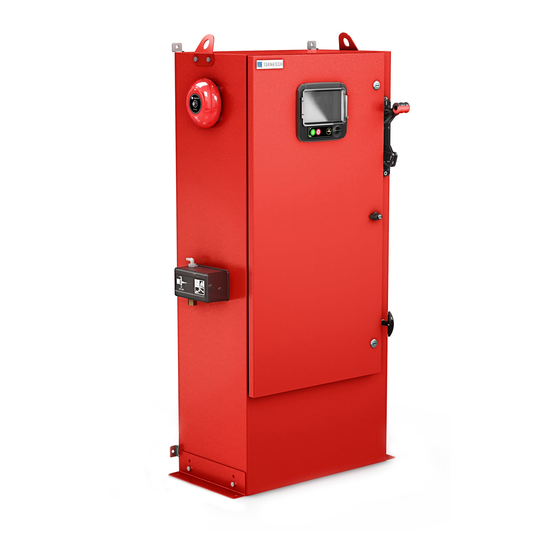
Tornatech GPX Installation And Maintenance Manual
Electric fire pump controllers with transfer switch
Hide thumbs
Also See for GPX:
- Installation and maintenance manual (59 pages) ,
- Installation and maintenance manual (20 pages)

Related Manuals for Tornatech GPX


Summary of Contents for Tornatech GPX
- Page 1 INSTALLATION AND MAINTENANCE MANUAL FOR ELECTRIC FIRE PUMP CONTROLLERS WITH TRANSFER SWITCH MODEL GPX + GPU...
- Page 2 Table of Contents 1. Introduction 2. Installation 3. Main Features 4. Home 5. Alarms 6. Configuration 7. History 8. Technical Documents GPXGPU-Manual-EN v1.3.0.0...
-
Page 3: Table Of Contents
Table of Contents Introduction ..................................5 Types of Electric Fire Pump Controllers ........................5 Types of Automatic Transfer Switch .......................... 6 Methods of Starting/Stopping ............................. 6 Transfer switch operation Sequence ......................... 7 Installation ..................................9 Location ..................................9 Mounting ..................................9 Storage .................................. - Page 4 Inputs/Outputs Expansion board 1-2-3-4 ......................... 36 Update Program Page ............................. 37 Factory Settings ............................... 37 Factory Settings ............................... 40 Reset to Factory Settings Page ..........................41 Service Page ................................42 New Pump Curve ..............................43 Automatic Pump Curve Mode Disabled ........................44 The Sensors Pages ..............................
-
Page 5: Introduction
Introduction Electric fire pump controllers are designed to start an electric motor driven fire pump. It can either start the fire pump manually through the local start pushbutton or automatically through the sensing of a pressure drop in the sprinkler system. The fire pump controller is supplied with a pressure transducer. The fire pump can be stopped manually with the local stop pushbutton or automatically after the expiration of a field programmable timer. -
Page 6: Types Of Automatic Transfer Switch
MODEL GPV: ACCELERATION RESISTOR STARTER This model does not require a multi-connection motor. It only requires 3 conductors between the controller and the motor. Upon a start command, a set of acceleration resistors in each phase is utilized to supply a reduced voltage to the motor. -
Page 7: Transfer Switch Operation Sequence
EMERGENCY START The motor can be started manually by using the emergency handle. This handle can be maintained in a closed position. Important: to avoid damaging the contactor, it is recommended to start the motor in this manner: 1) Shutdown the main power by using the main disconnect means, 2) Pull the emergency handle and lock it in closed position, 3) Turn the power back on by using the main disconnect means. - Page 8 When the Alternate Power Source is within acceptable limits (above 90% of the nominal voltage) for a certain set time (factory set at 3 seconds), the transfer to alternate power source is initiated. The transfer switch will remain in the alternate power source position until the normal source is restored. RETRANSFER TO NORMAL Important: The transfer switch will stay in alternate position, if the motor is running, for as long as the alternate power source is within acceptable limits.
-
Page 9: Installation
Installation The GPx electric fire pump controller is cULus listed, FM certified and is intended to be installed in accordance with the latest edition of the Standard of the National Fire Protection Association for the Installation of Centrifugal Fire Pumps, NFPA20 2016 (Centrifugal Fire Pumps) and... -
Page 10: Wiring And Connections
Wiring and Connections Water Connections The controller must be connected to the pipe system according to the latest edition of NFPA20 and also to a drain pipe. The water connections are on the left side of the controller. The connection to the system pressure is a Male ½... -
Page 11: Terminal Strip Descriptions
Terminal Strip Descriptions Alarm output terminals (SPDT Relay, 11:Common, 12:Normally Closed, 14:Normally Open): A: Motor Run B: Power Available (Failsafe relay) C: Phase Reversal D: Pump Room Alarm E: Motor Trouble F: Factory Reserved Field input terminal (Dry Contact Only: Voltage Free): G: Remote Manual Start (NO) H: Lockout (NO) I: Remote Automatic Start (NC) -
Page 12: Terminal Strip Descriptions
Terminal Strip Descriptions Outputs terminals: A: Transfer Switch in Alternate Position B: Transfer Switch in Normal Position C: Alternate Circuit Breaker Status D: Start/Stop Generator Signal Factory IO: E: Alternate position limit switches F: Normal position limit switches G: AIS/ACB limit switches H: ACB limit switch I: ACB shunt trip J: Transfer Switch motor... -
Page 13: Quick Start-Up Guide
Quick Start-Up Guide The rating label is the most important label. It must be read carefully to ensure the compatibility between the controller and the installation. Verify that the controller is installed securely on the wall, or optionally on the mounting stand. - Page 14 Make sure to drill holes for the motor and power connections and run the cables inside the panel, all in accordance with the specifications in order to minimize interference with other equipment. Verify and/or install the proper water connections for the water input and the drain. They must be securely installed and tightened.
- Page 15 Connect the normal input power, the alternate input power and the motor on their respective terminals. Secure with the appropriate torque as indicated on the torque label and verify all connections. Secure the doors in the closed position then put the normal power circuit breaker disconnecting means in the ON position.
- Page 16 Verify the motor rotation to ensure that the pump is turning in the right direction. The START and STOP push buttons can be used to toggle the motor ON/OFF. WARNING! On a Wye-Delta closed transition starter, if the transition from Wye to Delta occurs (after 5 to 8 seconds depending on the motor HP), the manual stop push button will be disabled for 80 seconds.
- Page 17 Verify that the alternate power is in the same phase order as the normal power. If required, change the alternate power wiring order to fit the one of the normal power.
- Page 18 The "First Setup" page replaces the Homepage until the "First Setup" is done. Proceed to the setup page and press the lock to enter your authorization code. Select the controller pressure units, cut-in and cut-out. Verify that all other parameters on the setup page are correct.
- Page 19 Proceed with the download step to save the report. Press the home page button to verify that the displayed values are correct.
- Page 20 The “First Start up” is now completed. The controller is fully installed and configured.
-
Page 21: Main Features
Main Features The ViZiTouch A: Power Available LED: Indicates that power is available. B: Touch Screen: 4.3 inches color touch screen LCD. C: Alarm LED: Indicates if an alarm is active. D: Front USB Connector: USB Device connector used for files download, software update, service reports. E: Home button: Used to navigate to the Home page. -
Page 22: Alarm Bell
R: Ethernet connector S: K-Type Thermocouple connector T: Alarm Bell connector Warning After 2 years of service, the Vizitouch battery may become less efficient and could lose the time after a shutdown. Alarm Bell The alarm bell is activated under default faulty conditions and under optional or user defined conditions. Any of these conditions will energize the alarm bell but may be silenced, except in some cases, by pressing on the “Alarms / silence”... -
Page 23: Home
Home Home (Membrane button) Home The home page displays all controller statuses and important values of the controller. All voltages, currents, pressure, motor state and status, as well as all timers and motor starting sequences. The entire background will become red if an alarm becomes active. This feature will help the user identify a problem even from a significant distance away from the controller. - Page 24 I: The alarm/warning notification. Warning indicator: Exclamation mark in a yellow round icon. If no alarm is in ACTIVE condition on the controller and at least one warning is ACTIVE or OCCURRED, the warning indicator will be present. Alarm indicator: Exclamation mark in a red triangle icon. As soon as at least one alarm is ACTIVE or OCCURRED, the alarm indicator will be flashing.
-
Page 25: Screen Saver
LOCK ROTOR CURRENT: A lock rotor current alarm has not been cleared on the alarms page and prevents the motor from starting. LOW PRESSURE: A low suction pressure prevents the motor from running, This functionality is optional. LOW WATER: A low water reservoir level prevents the motor from running, This functionality is optional. TRANSFER STOP: The transfer switch is transferring between power source and the motor is temporarily stopped in the process. -
Page 26: Alarms
Alarms Alarms (Membrane button) Alarms Displays the list of currently active and occurred alarms. An alarm is called ACTIVE when its triggering condition is still valid. An alarm is called OCCURRED when its triggering condition has been active, but is no longer true. Alarms representing serious concerns are colored RED. - Page 27 - Loss of power: Activates when a complete loss of normal power is detected. - Lock Rotor Current: Activates when a locked rotor condition has been detected on the normal power. Note that the motor will not be permitted to start on the normal power as long as this alarm has not been reset from the alarms page.
- Page 28 than the low spare temperature set point in the “Spare temperature” sensor page. - Alternate Isolating Switch Tripped/Opened**: Activates when the AIS is either tripped or opened. This alarm condition rings the bell and cannot be silenced. - Alternate CB Tripped/Opened**: Activates when the ACB is either tripped or opened. This alarm condition rings the bell and cannot be silenced.
- Page 29 - Pump on demand: Activates when the pressure is below the cut-in set-point on an automatic pressure actuated controller. - Controller Trouble: Important: this relay is normally energized when controller is in normal condition. The relay is de-energized when controller trouble is detected (fail safe). The controller trouble common alarm is active when one or more of these conditions are active: •...
-
Page 30: Configuration
Configuration Config (Membrane button) Config Setup all basic configuration parameters. The main configuration page provides a quick means of changing the most common settings. The padlock icon indicates the current authorization level. A locked padlock indicates that only basic settings can be changed. Press on the padlock to enter an authorization code to unlock additional settings. -
Page 31: Numpad Page
membrane. Press the button to modify the value of the manual "Run Test" duration. Inside the lower box, the Automatic Shutdown may be activated and the duration of the “Run Period Timer” is shown. To edit the “Run Period Timer”, refer to the “Timers” page in the advanced configuration pages. NumPad Page The NumPad is activated every time the user clicks on a white square box representing a number that can be set. -
Page 32: User Login Page / Keypad Page
The Date and Time can be configured by selecting the current month and year by pressing the arrow buttons on each side of the “Month-Year” display and selecting the day of the month by selecting the actual day. The time is set by pressing the two square boxes under the clock;... -
Page 33: Advanced Configuration Page
character and the "CA" button clears the whole text field. Simply click the "OK" button once the value is set. This type of text field is mostly used to generate a digital text indication for a custom alarm input. Advanced Configuration Page Config >... -
Page 34: Timers Page
Most common timers can be configured here. Note that any timer set to 0 will remove the delay in the decision process. Access level 1: - Motor starting and stopping: The sequential start timer set-point, in seconds, will delay an automatic motor starting. The run period timer, in minutes, will delay the stopping of the motor when the automatic run cause of an automatic stop configured controller has returned to normal and that no other run causes are present. -
Page 35: Voltage Calibration
Most common timers for the transfer switch control can be configured here. Note that any timer set to 0 will remove the delay in the decision process. Access level 1: - Cooling Time: Time delay after which a running generator can be shut down when all running causes have return to normal. -
Page 36: Inputs/Outputs Expansion Board 1-2-3-4
Inputs/Outputs Expansion board 1-2-3-4 Config > Advanced > Expansion Board 1-2-3-4 This page allows the configuration of both programmable inputs and outputs available on an IO Expansion board. Two buttons located far right navigates between the input and output section of the page. Input: The input page has four elements: The NO/NC setting, the "Digital Text Indication"... -
Page 37: Update Program Page
The factory settings are always pre-configured at the factory and set the main parameters of the controller. Most of the settings found on this page can only be changed by an authorized Tornatech employee and is protected by a level 8 password. - Page 38 that must be used with care and only if the factory was contacted first. See the “Reset to Factory Settings” help for more details. Voltage: Nominal voltage of the controller FLC: Full load current rating of the motor. LRC: Lock rotor current rating of the motor. Unless specified, this value is automatically set to six times the FLC. Phase: Input power number of phases.
- Page 39 than this value, the alarm/warning will be activated at the end of the programmed timer. Overcurrent: Sets the value in percentage of the motor's Full Load Current (FLA) and its associated delay. If the average current reading is higher than this percentage of the FLA, the alarm/warning will be Activated. Undercurrent: Sets the value in percentage of the motor's Full Load Current (FLA) and its associated delay.
-
Page 40: Factory Settings
The factory settings are always pre-configured at the factory and set the main parameters of the controller. Most of the settings found on this page can only be changed by an authorized Tornatech employee and is protected by a level 8 password. -
Page 41: Reset To Factory Settings Page
Transfer trouble time: Delay applied to avoid a false alarm during the transition from one source to the other. After this delay, if the control does not receive a clear position signal (transfer switch in Normal position or Alternate position), it will trigger a transfer switch trouble alarm. Limits switches are installed to indicate the transfer switch position. -
Page 42: Service Page
Config > Advanced > Service The upper left section hosts the Tornatech Inc. business card by default. This image can be changed by the service dealer to incorporate a customized image. The image must have been created by Tornatech Inc., sent to the service dealer and copied on a USB Device. -
Page 43: New Pump Curve
New Pump Curve Config > Advanced > Service > New Pump Curve The Service Dealer “New Pump Curve” Procedure This page allows the user to create a pump curve. At the bottom of the screen, there are 3 buttons: - Reset: Clears the data of the pump curve in progress. - Auto: Uses needed types of transducers to create the pump curve (Discharge pressure, Suction pressure and Flow sensor need to be installed.) - Save: Saves the pump curve and update the pump curve chronological order as displayed in the “History >... -
Page 44: Automatic Pump Curve Mode Disabled
To automatically create a pump curve, the discharge pressure, suction pressure and flow meter must all be installed on the controller. -Click on the “Auto” button -A series of validation will take place to ensure all data is valid. -After a pre-defined timer, the ViZiTouch will acquire all data from all sensors and fill the first row of the pump curve table. -
Page 45: The Sensors Pages
The Sensors Pages... - Page 46 Important Notice! Every analog sensor cable used for this controller should be shielded. The shield has to be grounded on the motor side. Not complying to these recommendations may affect the controller good functioning and void its warranty. In the ViZiTouch, all sensors refer to analog input connectors on the I/O board. They all have similar settings and configuration.
- Page 47 Suction Pressure: To set the pressure system unit, go the “Config” page. All pressure transducers share the same unit. The “suction pressure” sensor shares the same analog input (AI4) as the water level sensor. Only one of them can be installed at all time. Prior to installing one of them, the other one must be uninstalled by visiting its own sensor page.
-
Page 48: Details Of The Debug Page
1.Two actual points (low and high) are required. 2. Set the lowest point (usually 0). 3. Press the left read button. 4. Press the left rectangle text field and enter the value read on the external calibrated gauge. 5. Set a high point (usually the highest possible value will create the best calibration). 6. -
Page 49: Io Debug
This table displays all calibration parameters. The “Scaled” value is the final calculated value used in the ViZiTouch. It is calculated by multiplying the “Raw” value by the “Gain” coefficient and by adding the “Offset” value. This information is useful when debugging the analog inputs on the IO board. IO Debug Config >... -
Page 50: Inputs/Outputs Debug
The small white circle beside each signal is a representation of its state. If the white circle is filled with a green dot, then the signal is activated. Comparing these software signals and the physical state of the signal on the electronic board is the best way to troubleshoot. -
Page 51: Interlock Lockout
Interlock Lockout Config > Advanced > Interlock Lockout These pages allow to configure the Lockout input and the interlock output parameters. To be active, those options need to be assigned to an Input or an Output on the I/O board. Lockout is an Input that disables the motor from starting. -
Page 53: History
History History (Membrane button) History Select specific pages within the History section. Everything related to the statistics, events, pressure, power logs and the download to USB is available within the History page. -Events: This button leads to the “Events” page, which displays the most recent 500 events. Each event log contains the date and time of occurrence as well as a brief description of the event. -
Page 54: Details Of The History Page
Details of the History Page Events Page History > Events Log It shows the last 500 events which occurred in chronological order. The first column is the date, the second one is the time of occurrence and the third column is the “Event message”. To obtain a log that is older than 500 events, visit the “Download to USB Device”... - Page 55 To download information from the ViZiTouch to a USB Device a user with at least a “level 1” password must be logged in. The "Download to USB” button will execute the command. If a USB Device is not present or if there is an error, a message saying “Could not mount USB drive”...
-
Page 56: The Statistics
The Statistics First/Last Service Statistics History > Statistics since first/last service The following description applies to two pages, reachable by the “First Service Statistics” and the “Last Service Statistics” button on the History page. All statistics shown here are calculated since the first/last service was done. All dates are in the YYYY.MM.DD format and all time references are in the HH:MM:SS format. -
Page 57: All Time Statistics
-Maximum: Value of maximum temperature displayed in the system actual unit and the moment it was reached. -Average: Calculated value of the average temperature during that period displayed in the system actual unit. -Generator( for transfer switch models only): -Last Run: Date and time of the generator/second utility last run. -Run time: Total running time of the generator/second utility during that period. -
Page 58: Textual Mode
axis, the total scope time is shown. The contextual navigation pad is implemented in this page. It allows for quick navigation functions, like “Zoom in”, “Zoom out”, “Rewind”, “Forward” and “Textual Mode”. As always, clicking on the Navigation Pad Icon in the lower right corner of the screen will pop-up the Navigation Pad functions specific for this page. -
Page 59: Power Curves
Power Curves Graphical Mode History > Power Log Curves The power curve graphical mode contains two vertical axis. The first three curves, as seen on the legend, are the individual phase voltage between lines 1-2, 2-3 and 3-1. In case of fire pump models built with an automatic transfer switch, the phase voltages between lines represent voltage read from the alternate side of the controller when the alternate side is active. -
Page 60: Textual Mode
Textual Mode History > Power Log Text The “Power Log text” shows a table with 10 rows. The total number of rows available is 500 and the logs are sorted in chronological order. To see more logs, please download all logs on a USB Device. Description of the columns : -Date: Date when the log was recorded -Time: Time when the log was recorded... -
Page 61: Pump Curves
Pump Curves History > Pump Curves The vertical axis represents the pressure in the actual unit selected. Its scale is dynamic and will resize depending on the highest recorded value. The horizontal axis represents the flow in the actual unit selected. Its scale is dynamic and will resize depending on the highest recorded value. -
Page 62: Technical Documents
Technical Documents Patents Country Title Grant No Mechanical activator for contactor 2741881 Mechanical activator for contactor US8399788B2 Mechanical activator for electrical contactor 165512 Mechanical activator for electrical contactor 165514 Mechanical activator for electrical contactor D803794 Mechanical activator for electrical contactor Patent pending 002955393- Mechanical activator for electrical contactor... -
Page 63: Pre-Field Acceptance Test
Pre-Field Acceptance Test TORNATECH MODEL GPX WITH OR WITHOUT GPU TRANSFER SWITCH ELECTRIC FIRE PUMP CONTROLLER PRE- FIELD ACCEPTANCE TEST CHECK LIST Note: This document should be an official indication of whether or not the installation and general condition of the equipment is adequate for a field acceptance test. This document should also aid the individual responsible for executing the field acceptance test to decide whether or not to carry out the field acceptance test of the equipment. - Page 64 Tornatech Controller S/N: _________________________________________ Installation address: _________________________________________ _________________________________________ _________________________________________ Check list completed? _____________Yes _____________ No Check list completed by: __________________________________________ Company: __________________________________________ Date: __________________________________________ Witnessed By: __________________________________________ Comments: ___________________________________________________________________________ ___________________________________________________________________________ ___________________________________________________________________________ ___________________________________________________________________________...
-
Page 65: Field Acceptance Test Report
Field Acceptance Test Report TORNATECH MODEL GPX WITH OR WITHOUT GPU TRANSFER SWITCH ELECTRIC FIRE PUMP CONTROLLER FIELD ACCEPTANCE TEST REPORT Complete this first section if it was not completed during the Pre-Field Acceptance test Note: A manual or automatic start must only be executed if the motor and the pump have been cleared to be started by their respective official service technicians. - Page 66 Power Available connected? _____Yes _____ No Phase Reversal connected? _____Yes _____ No Other contacts supplied and connected? _____Yes _____ No Tornatech Controller S/N: _________________________________________ Installation address: _________________________________________ _________________________________________ Field Acceptance Test completed? _____Yes _____ No Field Acceptance completed by: __________________________________________...
Need help?
Do you have a question about the GPX and is the answer not in the manual?
Questions and answers