
Related Manuals for Tornatech HFD


Summary of Contents for Tornatech HFD
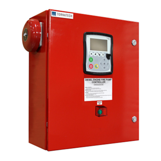
- Page 1 INSTALLATION AND MAINTENANCE MANUAL FOR DIESEL ENGINE FIRE PUMP CONTROLLERS MODEL HFD...
-
Page 2: Installation
Table of Contents 1. Introduction 2. Installation 3. Main Features 4. Home 5. Alarms 6. Configuration 7. History 8. Technical Documents HFD-Manual-EN v1.4.0.0... -
Page 3: Table Of Contents
Table of Contents Introduction ..................................5 Types of Diesel Engine Fire Pump Controllers ......................5 Methods of Starting/Stopping ............................. 5 Installation ..................................7 Location ..................................7 Mounting ..................................7 Storage ..................................7 Wiring and Connections ............................. 7 Electrical Connections..............................7 Energy Consumption .............................. - Page 4 I) Engine Coolant Temperature ..........................33 J) Engine Oil Pressure ............................. 34 K) Fuel Level ................................35 Details of the Debug Page ............................35 Calibration ................................35 IO Debug .................................. 36 Inputs/Outputs Debug .............................. 36 Interlock Lockout ..............................36 History ................................... 38 History (Membrane button) ............................
-
Page 5: Introduction
Types of Diesel Engine Fire Pump Controllers FIRE PUMP CATALOG NUMBER MODEL No. EXAMPLE : HFD-12-220 Model Prefix HFD Battery Voltage 12 : 12V 24 : 24V Incoming Voltage 220: 208/240V 50/60Hz Methods of Starting/Stopping The controllers are available as combination automatic / non-automatic. - Page 6 EMERGENCY STOP The emergency stop is always possible in any running condition and is done by pressing the Stop pushbutton for 8 seconds. This will activate the “Auto Mode Bypass”, stopping the engine and preventing the engine from starting automatically. Use only for maintenance operations..
-
Page 7: Installation
The mounting feet provide the necessary 12 in. (305 mm) clearance for current carrying parts. Storage If the controller is not installed and energized immediately, Tornatech recommend following the instructions from the chapter 3 of the NEMA ICS 15 standard. Wiring and Connections Electrical Connections A licensed electrician must supervise the electrical connections. -
Page 8: Energy Consumption
Energy Consumption Diesel Controller with boost charger Model / State 220/ VDC Output 240VAC 12VDC / @ No charge 1.0A 13.8V 12VDC / @ Full charge* 24VDC / @ No charge 0.5A 27.6V 24VDC / @ Full charge** *12 amps through each battery **10 amps through each battery Sizing Wiring between controller and engine (terminals 1,9,10,12) must be stranded #10AWG as minimum. -
Page 9: Terminal Strip Descriptions
Terminal Strip Descriptions A-F : Alarm Output Terminals (DPDT Relay, 11/21:Common, 12/22:Normally Closed, 14/24:Normally Open): A: Controller Trouble (Fail safe) B: Engine Run C: Automatic Mode Bypass (Fail safe) D: Fail to Start E: Engine Trouble F: Pump Room Alarm G-T : Field Input Terminal (Dry Contact Only: Voltage Free): G: Emergency Button... -
Page 10: Quick Start-Up Guide
Quick Start-Up Guide The rating label is the most important label. It must be read carefully to ensure the compatibility between the controller and the installation. Open the controller’s door and verify all circuit breakers are in the lower “OFF” position. - Page 11 Connect all engine cables between the control panel and the controller engine terminals (Identified as “S” on the IO board diagram that is displayed in the Terminal Strip Descriptions in the manual). Secure with the appropriate torque as indicated on the torque label and verify all connections. Connect the AC main lines and ground to the AC terminals in the controller.
- Page 12 The “First Setup” page replaces the Homepage until the “First Setup” is done. Verify that the controller reads the batteries voltage and current. Verify the “AC” is “OK” and not “FAIL”. Verify that the pressure reading is correct. Before trying to start the engine, verify that the engine setup is complete and the exhaust pipe is connected properly. Verify that the engine has started and is running properly.
- Page 13 Proceed with the download step to save the report. Press the home page button to verify that the displayed values are correct. The “First Start up” is now completed. The controller is fully installed and configured.
-
Page 14: Main Features
Main Features The ViZiTouch A: Power LED: Indicates if the ViZiTouch is properly powered. B: Touch Screen: 4.2 inches color touch screen LCD. C: Alarm LED: Indicates if an alarm is currently active. D: Front USB Connector: USB Device connector used for file download, software updates, service reports. E: Home button: Used to navigate to the Home page. -
Page 15: Alarm Bell
Warning After 2 years of service, the Vizitouch battery may become less efficient and could lose the time after a shutdown. Alarm Bell The alarm bell is activated under default faulty conditions and under optional or user defined conditions. Any of these conditions will energize the alarm bell but may be silenced, by pressing on the “Alarms / Silence” membrane button. -
Page 16: Home
Home Home (Membrane button) Home The home page displays all controller statuses and important values of the controller. All voltages, currents, engine state and status, as well as all timers and cranking sequences. The entire background will become red if an alarm becomes active. This feature will help the user identify a problem even at a significant distance away from the controller. -
Page 17: Screen Saver
D: Starter gear. It represents the current step of the cranking sequence. The counter inside indicates the step remaining time, counting down from 10 to 0 seconds. As there are two cranking modes, "waiting for crank" and "cranking", the gear will alternate between yellow and green, allowing the user to know exactly the state of the cranking sequence. -
Page 18: Alarms
Alarms Alarms (Membrane button) Alarms Displays the list of currently active and occurred alarms. An alarm is called ACTIVE when its triggering condition is present. An alarm is called OCCURED when its triggering condition has been active, but is no longer true. Alarms representing serious concerns are RED. - Page 19 CTRL Trouble: Important: this relay is normally energized when controller is in normal condition. The relay is de- energized when controller trouble is detected (fail safe). The controller trouble common alarm is active when one or more of these conditions are active : - Charger Failure 1-2 - DC failure - AC Failure: Monitors the AC power and activates on a failure.
- Page 20 - I/O_expX-inX alarm: Activates if the specific expansion programmable input on the specific expansion board is activated and triggered. - Battery1-2 Overvoltage: Activates if the voltage of the specific battery is higher than the specified overvoltage set point. - I/O Diesel Communication Error: Activates if no communication with the diesel I/O board could be established for 15 seconds.
-
Page 21: Configuration
Configuration Config (Membrane button) Config Setup all basic configuration parameters. The main configuration page provides a quick means of changing the most common settings. The padlock icon indicates the current authorization level. A locked padlock indicates that only basic settings can be changed. Press on the padlock to enter an authorization code to unlock additional settings. -
Page 22: Numpad Page
NumPad Page The NumPad is activated every time the user clicks on a white square box representing a number that can be set. On top of the NumPad, the current parameter is shown. The text will flash red if the value entered is invalid and the OK button will be black, indicating that the value is out of range. -
Page 23: User Login Page / Keypad Page
The Date and Time can be configured by selecting the current month and year by pressing the arrow buttons on each side of the “Month-Year” display and selecting the day of the month by selecting the actual day. The time is set by pressing the two square boxes under the clock;... -
Page 24: Advanced Configuration Page
character and the "CA" button clears the whole text field. Simply click the "OK" button once the value is set. This type of text field is mostly used to generate a digital text indication for a custom alarm input. Advanced Configuration Page Config >... - Page 25 calibration of the battery chargers in the “power supply” mode. To do so, simply turn the batteries circuit breaker to OFF. This page is used to calibrate all analog currents. The first number right beside the Battery 1 and Battery 2 text shows the actual current reading.
-
Page 26: Timers Page
Voltage Coast Drop Detection Enable : If enable, this second condition on the battery test is activated. On smaller battery, the rise in current during a boost test might be to small to have a conclusive test. This second test verify the capacitive effect on the battery line after a boost sequence. -
Page 27: Inputs/Outputs Configuration
If Enabled, this timer will delay the "Fail When Running Alarm". - Local Request Detection: This is the delay it will take to the controller to detect a Local start of the pump. The other timers are self explanatory and set the time delay on alarms. Inputs/Outputs Configuration Config >... - Page 28 This page allows the configuration of alarm signals on the inputs, and outputs relay signals. Two buttons located far right navigates between the input and output section of the page. Input: The input page has four elements: The NO/NC setting, the “Digital Text Indication” field, the “Alarm Bell Icon” and the “Alarm Icon”.
-
Page 29: Inputs/Outputs Expansion Board 1-2-3-4
Inputs/Outputs Expansion board 1-2-3-4 Config > Advanced > Expansion Board 1-2-3-4 This page allows the configuration of both programmable inputs and outputs available on an IO Expansion board. Two buttons located far right navigates between the input and output section of the page. Input: The input page has four elements: The NO/NC setting, the "Digital Text Indication"... -
Page 30: Update Program Page
Update Program Page This procedure is highly important and must be attempted with care. Please make sure to contact the factory prior to using the Update Software function. Factory Settings Config > Advanced > Factory Settings This page is only avalable if one or more Expansion Board is installed as an option. The factory settings are always pre-configured at the factory and set the main parameters of the controller. -
Page 31: Reset To Factory Settings Page
“Factory Reset”. Its purpose is to allow an update of configuration variables that can only be updated by Tornatech Inc. All other square buttons on this page are “Level 9” security and can only be used by certified Tornatech representatives, unless otherwise specified. The first square in the upper left corner performs the “Select all”... -
Page 32: The Sensors Pages
The Sensors Pages Important Notice! Every analog sensor cable used for this controller should be shielded. The shield has to be grounded on the motor side. Not complying to these recommendations may affect the controller good functioning and void its warranty. H) Tachometer (Engine Speed Switch) The tachometer (analog speed reading) gives the possibility to support engine with no electronic speed switch. -
Page 33: I) Engine Coolant Temperature
The left section is use to show the “Disable/Enable” state of the engine RPM Counter. The “teeth” input box allows the user to match the number of teeth on the flywheel. This is an important setting to allow a precise calculation of the RPM. -
Page 34: J) Engine Oil Pressure
The left section is use to show the “Installed” state of the Engine Temperature Sender. The rest of the page is already explained in the “Analog sensors” section of the manual. If the “Calibration Type” is selected to be “Log. Resistor”, the bottom section will allow the user to directly change the “Gain”... -
Page 35: K) Fuel Level
The left section is use to show the “Installed” state of the Oil Pressure Sender. The rest of the page is already explained in the “Analog sensors” section of the manual. If the “Calibration Type” is selected to be “Lin. Resistor”, the bottom section will allow the user to directly enters the First point (resistor-pressure) and Second point (resistor-pressure) values, depending on the sender’s model. -
Page 36: Io Debug
IO Debug Config > Advanced > Debug > IO The small white circle beside each signal is a representation of its state. If the white circle is filled with a green dot, then the signal is activated. Comparing these software signals and the physical state of the signal on the electronic board is the best way to troubleshoot. - Page 37 These pages allow to configure the Lockout input and the interlock output parameters. To be active, those options need to be assigned to an Input or an Output on the I/O board. Lockout is an Input that disables the engine from starting. - Enable in emergency: If checked, this option will prevent the electronic assistance on an Emergency start.
-
Page 38: History
History History (Membrane button) History Select specific pages within the History section. Everything related to the statistics, events, pressure, power logs and the download to USB is available within the History page. -Events: This button leads to the “Events” page, which displays the most recent 500 events. Each event log contains the date and time of occurrence as well as a brief description of the event. -
Page 39: Details Of The History Page
Details of the History Page Events Page History > Events Log It shows the last 500 events which occurred in chronological order. The first column is the date, the second one is the time of occurrence and the third column is the “Event message”. To obtain a log that is older than 500 events, visit the “Download to USB Device”... - Page 40 To download information from the ViZiTouch to a USB Device a user with at least a "level 1" password must be logged in. The first square beside the title is a "Select All" button. Pressing it will select all categories except "Archive copied files", which serves a separate purpose.
-
Page 41: The Statistics
The Statistics All Time Statistics History > All Time Statistics All statistics shown here are calculated since the controller's first start-up was done. All dates are in the YYYY.MM.DD format and all time references are in the HH:MM:SS format. -First Power Up: Date and time of when the controller was first powered up. -First Start Up: Date and time of when the controller's first start-up was completed. -
Page 42: Technical Documents
Technical Documents How to Test: Charger 1 Fail Unpower the charger 1 by putting the circuit breaker in the off position. Charger 2 Fail Unpower the charger 2 by putting the circuit breaker in the off position. DC Failure Switch Circuit Breaker 3 (CB3) and Circuit Breaker 4 (CB4) in Off position or disconnect #6 and #8 engine wires (See drawing for more details). - Page 43 Overspeed You need to be logged in to do this test. Press Config button (On the membrane). Go to Config>Advanced>Engine Speed. Start your engine. Press Overspeed Test button. Electronic Control Module Selector Switch in Alternate Position (301) Disconnect #301 engine wire. Put a jumper between #301 input and ground (See drawing for more details). Fuel Injection Malfunction (302) Disconnect #302 engine wire.
- Page 44 Engine Trouble To activate this common alarm, at least one of the following alarms must be active: Fail to start, Overspeed, Electronic Control Module Selector Switch in Alternate Position (301), Fuel Injection Malfunction (302), Electronic Control Module Warning (303), Electronic Control Module Fault (304), Low Engine Temperature (312), Low Oil Pressure, High Engine Temperature, Battery 1 Failure, Battery 2 Failure, Loss of Continuity 1, Loss of Continuity 2, Overpressure or Low Pneumatic Pressure Low Spare Temperature...
- Page 45 Patents Country Title Grant No Mechanical activator for contactor 2741881 Mechanical activator for contactor US8399788B2 Mechanical activator for electrical contactor 165512 Mechanical activator for electrical contactor 165514 Mechanical activator for electrical contactor D803794 Mechanical activator for electrical contactor Patent pending 002955393- Mechanical activator for electrical contactor 0001/2...
- Page 46 TORNATECH MODEL HFD DIESEL FIRE PUMP CONTROLLER PRE- FIELD ACCEPTANCE TEST CHECK LIST Note: This document should be an official indication of whether or not the installation and general condition of the equipment is adequate for a field acceptance test. This document should also aid the individual responsible for executing the field acceptance test to decide whether or not to carry out the field acceptance test of the equipment.
- Page 47 Tornatech Controller S/N: _________________________________________ Installation address: _________________________________________ _________________________________________ _________________________________________ Check list completed? _____________Yes _____________ No Check list completed by: __________________________________________ Company: __________________________________________ Date: __________________________________________ Witnessed By: __________________________________________ Comments: ___________________________________________________________________________ ___________________________________________________________________________ ___________________________________________________________________________ ___________________________________________________________________________ ___________________________________________________________________________ ___________________________________________________________________________...
Need help?
Do you have a question about the HFD and is the answer not in the manual?
Questions and answers