
Related Manuals for Kramer VS-622DT


Summary of Contents for Kramer VS-622DT
- Page 1 USER MANUAL MODEL: VS-622DT 6x2 HDMI/HDBT Audio Matrix Switcher P/N: 2900-300856 Rev 1 www.KramerAV.com...
-
Page 2: Table Of Contents
Defining VS-622DT Installing in a Rack Connecting VS-622DT Connecting the Audio Outputs Connecting to VS-622DT via RS-232 Connecting VS-622DT via the Ethernet Port Operating VS-622DT via Front Panel Buttons Capturing the EDID Using the Web Pages Switching and Setting Ports... -
Page 3: Introduction
Kramer Electronics Ltd. Introduction Welcome to Kramer Electronics! Since 1981, Kramer Electronics has been providing a world of unique, creative, and affordable solutions to the vast range of problems that confront the video, audio, presentation, and broadcasting professional on a daily basis. In recent years, we... -
Page 4: Overview
European Advanced Recycling Network (EARN) and will cover any costs of treatment, recycling and recovery of waste Kramer Electronics branded equipment on arrival at the EARN facility. For details of Kramer’s recycling arrangements in your particular country go to our recycling pages at www.kramerav.com/support/recycling. -
Page 5: Typical Applications
Kramer Electronics Ltd. • Kramer ReKlocking™ & Equalization Technology – Rebuilds the digital signal to travel longer distances. • Static or dynamic DHCP IP addressing. Advanced and User-friendly Operation • Simple and Powerful Maestro 1.5 Room Automation – Intuitive user interface enables you to fully automate your meeting room elements. -
Page 6: Controlling Your Vs-622Dt
Front Panel Buttons on page 14), or: • By RS-232 serial commands transmitted by a touch screen system, PC, or other serial controller (see Connecting to VS-622DT via RS-232 on page 10). • Remotely, using the infrared remote-control transmitter. •... -
Page 7: Defining Vs-622Dt
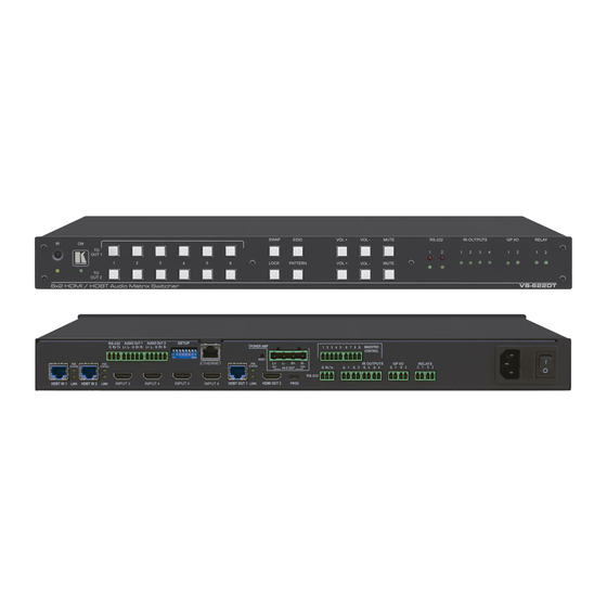
Kramer Electronics Ltd. Defining VS-622DT This section defines VS-622DT. Figure 1: VS-622DT 6x2 HDMI/HDBT Audio Matrix Switcher Front Panel Feature Function IR LED Lights yellow when the unit accepts IR remote commands. IR Receiver Receives signals from the remote-control transmitter. - Page 8 Kramer Electronics Ltd. Figure 2: VS-622DT 6x2 HDMI/HDBT Audio Matrix Switcher Rear Panel Feature Function HDBT IN 1 RJ-45 Connectors Connect to an HDBT transmitter (for example, TP-580Txr). (1 to 2) POE STATUS and LINK LEDs Light when PoE is available and an HDBaseT link is established (HDBT IN 1, HDBT IN 2 and HDBT OUT 1).
-
Page 9: Installing In A Rack
Kramer Electronics Ltd. Installing in a Rack This section provides instructions for rack mounting VS-622DT. Before installing in a rack, verify that the environment is within the recommended range: • Operation temperature – 0 to 40C (32 to 104F). •... -
Page 10: Connecting Vs-622Dt
Kramer Electronics Ltd. Connecting VS-622DT Always switch off the power to each device before connecting it to your VS-622DT. After connecting your VS-622DT, connect its power and then switch on the power to each device. Note that not all the ports are connected in the following example. - Page 11 Connecting the Ethernet port of the HDBT transmitters/receivers to the network switch port in conjunction with Ethernet port network connection on the VS-622DT, will cause network loops that may cause Ethernet switch network breakdown. 6. Connect IR OUT 4 2-pin terminal blocks (1 to 4) to an IR emitter and attach the emitter to a controlled device (for example, a Blu-ray player).
-
Page 12: Connecting The Audio Outputs
Figure 5: Connecting the Output to an Figure 4: Connecting the Output to a Balanced Unbalanced Stereo Audio Acceptor Stereo Audio Acceptor Connecting to VS-622DT via RS-232 You can connect to the VS-622DT via an RS-232 connection to the Control RS-232 port using, for example, a PC;... -
Page 13: Connecting Vs-622Dt Via The Ethernet Port
Kramer Electronics Ltd. Connecting VS-622DT via the Ethernet Port You can connect to the VS-622DT via Ethernet using either of the following methods: • Directly to the PC using a crossover cable (see Connecting the Ethernet Port Directly to a on page 11). - Page 14 6. Select Use the following IP Address for static IP addressing and fill in the details as shown in Figure For TCP/IPv4 you can use any IP address in the range 192.168.1.1 to 192.168.1.255 (excluding 192.168.1.39) that is provided by your IT department. VS-622DT – Connecting VS-622DT...
- Page 15 Connecting the Ethernet port of the HDBT transmitters/receivers to the network switch port in conjunction with Ethernet port network connection on the VS-622DT, will cause network loops that may cause Ethernet switch network breakdown. Control Configuration via the Ethernet Port To control several units via Ethernet, connect the Master unit (Device 1) via the Ethernet port to the Ethernet port of your PC.
-
Page 16: Operating Vs-622Dt Via Front Panel Buttons
2. For each input to which you want to copy the default EDID, press both the To OUT 1 and To OUT 2 buttons simultaneously. Both top row and bottom row input LEDs light. 3. Press EDID. The EDID changes are saved and the button no longer lights. VS-622DT – Operating VS-622DT via Front Panel Buttons... -
Page 17: Using The Web Pages
Viewing General Information on page 49. Before attempting to connect: • Perform the procedures in Connecting VS-622DT via the Ethernet Port on page 11. • Ensure that your browser is supported. The following operating systems and Web browsers are supported:... - Page 18 Figure 12: Using the Embedded Web Pages – Authentication Window 3. Enter the User Name and Password (Admin, Admin by-default) and click OK. The Routing page appears. Figure 13: Routing Page with Navigation List on Left VS-622DT – Using the Web Pages...
-
Page 19: Switching And Setting Ports
The Routing page enables performing the following functions: • Routing Video Inputs on page 18. • Switching a Pattern to the Outputs on page 20. • Adjusting Audio Settings on page 21. • Switching Data on page 22. VS-622DT – Using the Web Pages... - Page 20 • Click on an input button to disable/enable HDCP support. • Click on an input button to configure remote device buttons, see Setting Remote Devices on page 19. VS-622DT – Using the Web Pages...
- Page 21 When the HDMI/HDBT output of a step-in device (for example, the SID-X3N, DIP-30, DIP-31 For HDMI inputs and DIP-20 for HDBT inputs) is connected to an input on the VS-622DT, you can program the step-in buttons via automation (see Configuring Room Automation on page...
- Page 22 3. Click a pattern. The selected pattern is switched to both output/s (for example, pattern 1 is switched to outputs 1 and 2). Figure 16: Routing Page – Switching a Pattern to the Outputs VS-622DT – Using the Web Pages...
- Page 23 Slide the OUT 1 and OUT 2 sliders to set the audio level on each output (or type the value below the slider and then click anywhere outside that text box). • Click Swap to swap the audio outputs. • Click to mute an output and to unmute an output. VS-622DT – Using the Web Pages...
- Page 24 Direct Control. Some step-in devices can function even if Data Switching is set to Follow Video. Setting data switching to Direct Control disables RS-232 data routing between the HDBT inputs and the HDBT output. VS-622DT – Using the Web Pages...
-
Page 25: Managing Edid
You can copy the EDID from a selected output to any or all the inputs. To copy an EDID from an output to an input: 1. In the Navigation pane, click EDID Management. The EDID Management page appears. Figure 19: EDID Management Page VS-622DT – Managing EDID... - Page 26 Figure 20: EDID Management Page – Select an EDID Output (Read From) If you are reading EDID from an output, make sure that that output is connected to an acceptor. For example, Output 1 is disconnected and Output 2 is connected to an acceptor: VS-622DT – Managing EDID...
- Page 27 Figure 21: EDID Management Page – Select the Inputs (Copy to) 4. Click COPY. The Output 2 EDID is copied to the selected inputs. Figure 22: EDID Management Page – EDID Copied The EDID copy success message appears: 5. Click OK. VS-622DT – Managing EDID...
-
Page 28: Copying Edid From An Input To An Input
1. In the Navigation pane, click EDID Management. The EDID Management page appears (see Figure 19). 2. Select the EDID source (for example, Input 2). Figure 23: EDID Management Page – Select an EDID Input (Read From) VS-622DT – Managing EDID... - Page 29 Figure 24: EDID Management Page – Select the Inputs (Copy to) 4. Click COPY. The Input 2 EDID is copied to the selected inputs. Figure 25: EDID Management Page – EDID Copied The EDID copy success message appears. 5. Click OK. VS-622DT – Managing EDID...
-
Page 30: Copying Edid From The Default Edid To An Input
EDID that the device reads. 2. In the File area click “…”. 3. Select the EDID file. 4. Select the input/s (or all the inputs) to which the EDID is copied. 5. Click Copy and follow the instructions on-screen. VS-622DT – Managing EDID... -
Page 31: Changing The Device Settings
To save the current configuration: 1. In the Navigation pane, click Device Settings. The General tab in the Device Settings page appears: Figure 26: Device Settings Page – General Tab VS-622DT – Changing the Device Settings... -
Page 32: Resetting To Factory Default Parameters
The Communication tab enables performing the following functions: • Changing Ethernet Settings when DHCP is Off on page 31. • Changing Ethernet Settings when DHCP is On on page 32. • Setting DHCP to Off on page 33. VS-622DT – Changing the Device Settings... - Page 33 Kramer Electronics Ltd. Changing Ethernet Settings when DHCP is Off After changing the Mask address, you need to power cycle the VS-622DT. To change the Ethernet settings: 1. In the Navigation pane, click Device Settings. The Device Settings page appears.
- Page 34 5. Click Yes. 6. Type the device name in the address bar of your browser to reload the page. You can read the new IP address from the Network Settings page. DHCP is ON. VS-622DT – Changing the Device Settings...
- Page 35 Figure 31: Device Settings Page – DHCP ON Message 4. Check Custom IP and enter an IP address or Check Default IP. 5. Click Apply. The web page reloads with the new IP address. VS-622DT – Changing the Device Settings...
-
Page 36: Setting The Date And Time
Click the Device Date text box and change the date. ▪ Click the Device Time text box and change the time. ▪ Select the Time Zone. ▪ Click YES to set to Daylight Savings Time. The date and time are set. VS-622DT – Changing the Device Settings... -
Page 37: Upgrading The Firmware
The date and time are set. Upgrading the Firmware To perform firmware upgrade: 1. In the Navigation pane, click Device Settings. The Device Settings page appears. 2. Select the FW Upgrade tab. 3. Click Update. VS-622DT – Changing the Device Settings... - Page 38 Figure 35: Device Settings Page – Firmware Upgrade Process 6. Wait for the device to restart. Figure 36: Device Settings Page – Uploading New Firmware The firmware is upgraded and the web pages reload. VS-622DT – Changing the Device Settings...
-
Page 39: Setting Authentication
To access Web pages using the password: 1. In the Navigation pane, click Device Settings and select the Authentication tab. The Authentication page appears: Figure 37: Authentication Page – Security Disabled 2. Click Enabled. A confirmation page appears. VS-622DT – Changing the Device Settings... - Page 40 6. Change the password as instructed and click Change. A confirmation message appears. 7. Click OK. A success message appears. 8. Click OK. The web page reloads, security is enabled, and access is password restricted. VS-622DT – Changing the Device Settings...
- Page 41 1. In the Navigation pane, click Device Settings and select the Authentication tab. The Authentication page appears (see Figure 39). 2. Click Disabled. The Confirmation message appears: Figure 40: Authentication Page – Disabling Authentication 3. Type the current password and click OK. Security is disabled. VS-622DT – Changing the Device Settings...
-
Page 42: Managing Io Gateway Settings
3. Optionally, configure the following: ▪ Set the protocol to UDP or TCP. ▪ Enter the port number. ▪ Set the TCP Keep Alive time (duration between two transmissions to prevent the link to be broken). VS-622DT – Managing IO Gateway Settings... - Page 43 2. Click Active Clients and view the following. IP – Client IP address. ▪ ▪ To – The port to which it is connected on the VS-622DT. ▪ Through – Method of connection (UDP or TCP). ▪ S/R (Send Replies) – enabled/disabled for the port (see Figure 41).
-
Page 44: Setting Gpi/O Parameters
To configure the digital input trigger type: 1. In the Navigation pane, click IO Gateway. The IO Gateway page appears (see Figure 41). 2. Click GPIO. The GPIO tab appears. Figure 43: IO Gateway Page – GPIO Tab VS-622DT – Managing IO Gateway Settings... - Page 45 7. Once connected, click Read to view the current state (High or Low) and voltage of the port. 8. Click Save Changes. The Digital IN GPIO port is configured. The default parameter settings change depending on which trigger type is selected. VS-622DT – Managing IO Gateway Settings...
- Page 46 Use this setup to control devices that accept a TTL signal such as LED powering. Set the trigger type to Digital OUT. With this selection, the external device, (for example, an electric blind) is controlled by the VS-622DT. To configure the digital output trigger type: 1.
- Page 47 To configure the analog input trigger type: 1. In the Navigation pane, click IO Gateway. The IO Gateway page appears (see Figure 41). 2. Click GPIO. The GPIO tab appears (see Figure 43). 3. Select GPIO 1 or GPIO 2. VS-622DT – Managing IO Gateway Settings...
- Page 48 Figure 47: IO Gateway Page – GPIO Analog IN Settings 5. Set the number of steps. 6. Once connected, click Read to view the step number and the voltage. 7. Click Save Changes. The Analog IN GPIO port is configured. VS-622DT – Managing IO Gateway Settings...
-
Page 49: Setting Relays
Web pages or a P3000 command. To close a relay: 1. In the Navigation pane, click IO Gateway. The IO Gateway page appears. 2. Click Relay. The Relay tab appears. 3. Click Close. The relay closes. VS-622DT – Managing IO Gateway Settings... -
Page 50: Configuring Room Automation
1. In the Navigation pane, click Automation. The Maestro page appears. Figure 49: Automation – Maestro Page For further details on how to use room automation, refer to the Kramer Maestro User Manual, available at www.kramerav.com/downloads/VS-622DT. VS-622DT – Configuring Room Automation... -
Page 51: Viewing General Information
Kramer Electronics Ltd. Viewing General Information VS-622DT About page lets you view the web page version and Kramer Electronics Ltd details. Figure 50: About Page VS-622DT – Viewing General Information... -
Page 52: Technical Specifications
Programmable Maestro buttons interface Windows 7 Supported Internet Explorer, Firefox, Chrome, Safari Browsers Windows 10 Internet Explorer, Edge, Firefox, Chrome MAC 10.11 Safari iOS 10.3.2 Safari Android Power Consumption 250VA max. Source 100-240V AC VS-622DT – Technical Specifications... -
Page 53: Default Parameters
“#FACTORY” command followed by #RESET command. Protocol 3000: Web Pages: In the Device Settings page, General tab, click Factory reset. Amplifier Values Amplifier output mode: Lo-Z Speaker output from: OUT 1 Web pages Authentication User name: Admin Password: Admin VS-622DT – Technical Specifications... -
Page 54: Protocol 3000
You can enter commands directly using terminal communication software (e.g., Hercules) by connecting a PC to the serial or Ethernet port on the VS-622DT. To enter ␍ press the Enter key (␊ is also sent but is ignored by the command parser). -
Page 55: Understanding Protocol 3000
Spaces between parameters or command terms are ignored. Commands in the string do not execute until the closing character is entered. A separate response is sent for every command in the chain. VS-622DT – Protocol 3000... -
Page 56: Kramer Protocol 3000 Syntax
Kramer Electronics Ltd. Kramer Protocol 3000 Syntax The Kramer Protocol 3000 syntax uses the following delimiters: • CR = Carriage return (ASCII 13 = 0x0D) • LF = Line feed (ASCII 10 = 0x0A) • SP = Space (ASCII 32 = 0x20) Some commands have short name syntax in addition to long name syntax to enable faster typing. -
Page 57: Protocol 3000 Commands
Set/get device time and date TIME-LOC Set/get local time offset from UTC/GMT AV-SW-MODE Get auto switch mode BAUD Set/get protocol serial baud rate DPSW-STATUS Get the DIP-switch status FEATURE-LIST Get feature state according to feature ID PRIO Get input priority VS-622DT – Protocol 3000... - Page 58 ~nn@FACTORYSPOKCR LF Notes This command deletes all user data from the device. The deletion can take some time. Your device may require powering off and powering on for the changes to take effect. K-Config Example “#FACTORY”,0x0D VS-622DT – Protocol 3000...
- Page 59 – String of up to 19 printable ASCII chars Notes This command identifies equipment connected to Step-in master products and notifies of identity changes to the connected equipment. The Matrix saves this data in memory to answer REMOTE-INFO requests. K-Config Example “#MODEL?”,0x0D VS-622DT – Protocol 3000...
- Page 60 To avoid locking the port due to a USB bug in Windows, disconnect USB connections immediately after running this command. If the port was locked, disconnect and reconnect the cable to reopen the port. K-Config Example “#RESET”,0x0D VS-622DT – Protocol 3000...
- Page 61 VERSION Functions Permission Transparency Set: VERSION? Get: End User Public Description Syntax Set: Get firmware version number #VERSION?CR Get: Response ~nn@VERSIONSPfirmware_versionCR LF Parameters firmware_version – XX.XX.XXXX where the digit groups are: major.minor.build version K-Config Example “#VERSION?”,0x0D VS-622DT – Protocol 3000...
- Page 62 After every change in output HPD status from Off to On (1) After every change in output HPD status form Off to On and all parameters (new EDID, etc.) are stable and valid (2) K-Config Example Get the output HPD status of Output 1: “#DISPLAY? 1”,0x0D VS-622DT – Protocol 3000...
- Page 63 Set HDCP working mode on the device input: HDCP supported – HDCP_ON (default) HDCP not supported – HDCP OFF HDCP supports changes following a detected sink - MIRROR OUTPUT K-Config Example Set the input HDCP-MODE of IN 1 to Off: “#HDCP-MOD 1,0”,0x0D VS-622DT – Protocol 3000...
- Page 64 Lock front panel #LOCK-FP? Get: Get front panel lock state Response ~nn@LOCK-FPSPlock_modeSPOKCR LF Parameters lock_mode – 0 (Off, unlock the front panel buttons), 1 (On, lock the front panel buttons) K-Config Example Unlock front panel: “#LOCK-FP 0”,0x0D VS-622DT – Protocol 3000...
- Page 65 Get: Response ~nn@NAME-RSTSPOKCR LF Notes Factory default of machine (DNS) name is “KRAMER_” + 4 last digits of device serial number K-Config Example Reset the machine name (S/N last digits are 0102): “#NAME-RST KRAMER_0102”,0x0D VS-622DT – Protocol 3000...
- Page 66 The device does not validate the day of week from the date. Time format – 24 hours Date format – Day, Month, Year K-Config Example Set device time and date to December 5, 2018 at 2:30pm: “#TIME MON 05-12-2018,14:30:00”,0x0D VS-622DT – Protocol 3000...
- Page 67 – for video layer: 0 (HDBT Out 1) 1 (HDMI Out 2) mode - 0 (Manual), 1 (Priority switch), 2 (Last connected switch) K-Config Example Get the input audio switch mode for HDMI Out: “#AV-SW-MODE? 1,1”,0x0D VS-622DT – Protocol 3000...
- Page 68 #DPSW-STATUS?SPdp_sw_idCR Get : Get the DIP-switch state Response ~nn@DPSW-STATUS?SPdp_sw_id, statusCR LF Parameters dp_sw_id – 1 to 8 (num of DIP switches) status – 0 (up), 1 (down) K-Config Example get the DIP-switch 2 status: “#DPSW-STATUS? 2”,0x0D VS-622DT – Protocol 3000...
- Page 69 After execution, response is sent to all com ports if PRIO was set by any other external control device (button press, device menu and similar) Notes The PRIO max value may vary for different devices K-Config Example Get INPUT 3 assigned priority: “#FEATURE-LIST? 3”,0x0D VS-622DT – Protocol 3000...
- Page 70 Kramer Electronics Ltd. EDID Handling Commands Additional EDID data functions can be performed via the VS-622DT web pages or a compatible EDID management application, such as Kramer EDID Designer (see www.kramerav.com/product/EDID%20Designer). Command Description CPEDID Copy EDID data from the output to the input EEPROM...
- Page 71 After execution, a response is sent to all comm ports if MTX-MODE was set by any other external control device (button press, WEB, device menu and similar) Notes Not recommended for new devices K-Config Example Get the auto switch mode of HDMI Out: “#MTX-MODE? 1”,0x0D VS-622DT – Protocol 3000...
- Page 72 – Source ID: 1 (Input 1) to 6 (Input 6) Notes This command replaces all other routing commands K-Config Example Set the remote input switching of video to HDBT OUT 1 from HDMI In 2: “#ROUTE 1,1,2”,0x0D VS-622DT – Protocol 3000...
- Page 73 The SET command is for remote input switching on Step-in clients (essentially via by the Web) This is a legacy command. New Step-in modules support the ROUTE command K-Config Example Get the remote info of the step-in device (DIP-30) that is connected to input 3: “#REMOTE-INFO 0,3”,0x0D VS-622DT – Protocol 3000...
- Page 74 The SET command is for remote input switching on Step-in clients (essentially via by the Web) This is a legacy command. New Step-in modules support the ROUTE command K-Config Example Set the video switch state of INPUT 1 to HDBT OUT 1: “#VID 1>1”,0x0D VS-622DT – Protocol 3000...
- Page 75 AUD-SWAP? Get: End User Public Description Syntax #AUD-SWAPSPswap_modeCR Set: Set audio output swap #AUD-SWAP?CR Get: Get audio output swap status Response ~nn@AUD-SWAPSPswap_modeCR LF Parameters swap_mode – 0 (OFF), 1 (ON) K-Config Example Swap outputs: “#AUD-SWAP 1”,0x0D VS-622DT – Protocol 3000...
- Page 76 HiZVolt – Hi-Z volt level: 0 (70 Volt), 1 (100 Volt), 0xff (Ignore). Optional, active only in high state Notes Active only when state is high. Ignore everything else. K-Config Example Set the line level output to Hi-Z and 70V: “#AUD-HI-Z 2,1,0”,0x0D VS-622DT – Protocol 3000...
- Page 77 – device model name – device name Response Triggers After execution, notification is sent containing beacon information. Notes There is no Set command. The port_id parameter is not necessary and can be omitted. Example Get beacon information: #BEACON-INFO?<CR> VS-622DT – Protocol 3000...
- Page 78 – network mask, in the following format: xxx.xxx.xxx.xxx gateway – network gateway, in the following format: xxx.xxx.xxx.xxx Example Set the device network parameters to IP address 192.168.113.10, net mask 255.255.0.0, and gateway 192.168.0.1: #NET-CONFIG 0,192.168.113.10,255.255.0.0,192.168.0.1<CR> VS-622DT – Protocol 3000...
- Page 79 A network gateway connects the device via another network, possibly over the Internet. Be careful of security problems. Consult your network administrator for correct settings. K-Config Example Set the gateway IP address to 192.168.0.1: “#NET-GATE 192.168.000.001”,0x0D VS-622DT – Protocol 3000...
- Page 80 Functions Permission Transparency Set: NET-MAC? Get: End User Public Description Syntax Set: #NET-MAC?CR Get: Get MAC address Response ~nn@NET-MACSPmac_addressCR LF Parameters mac_address – unique MAC address. Format: XX-XX-XX-XX-XX-XX where X is hex digit K-Config Example “#NET-MAC?”,0x0D VS-622DT – Protocol 3000...
- Page 81 – time server IP address or hostname. IP must be, in the following format: xxx.xxx.xxx.xxx time_server_sync_hour – not in use: 0 server_status – 0 (OFF), 1 (ON) Notes This command sets up the NTP server. Example Set time server with IP address of 128.138.140.44 to ON: #TIME-SRV 1, 128.138.140.44,0,1<CR> VS-622DT – Protocol 3000...
- Page 82 – none, odd, even, mark, space, n, o, e, m, s stop_bits – 1, 2 stop bits K-Config Example Set baud rate to 9600, 8 data bits, parity to none and stop bit to 1: “#UART 9600,8,node,1”,0x0D VS-622DT – Protocol 3000...
- Page 83 This command sets tunneling port routing. Every com port can send or receive data from the ETH port. All com ports can be configured to the same ETH port. K-Config Example Set tunnel port 1 routing: “#COM-ROUTE 1,2,5001,0,40”,0x0D VS-622DT – Protocol 3000...
- Page 84 Get data tunneling mode Response ~nn@FVSP1,modeCR LF Parameters output –1 (HDBT OUT 1) mode – 0 (data connected to MCU, direct control), 1 (Data follows video) K-Config Example Set set data tunneling to follow video: “#FV 1,1”,0x0D VS-622DT – Protocol 3000...
- Page 85 The device uses this command to notify the user of any change regarding the step and voltage in: In digital mode the answer is 0 (low), 1 (high) In analog mode the answer is 0 to 100 K-Config Example Set GPIO 2 to High: “#GPIO-STATE 2,1”,0x0D VS-622DT – Protocol 3000...
- Page 86 HwGpioNum – 1 (GPIO 1), 2 (GPIO 2) LowLevel – voltage 500 to 28000 millivolts HighLevel – voltage 2000 to 30000 millivolts K-Config Example Set GPIO 2 to a low level of 800mV and a high level of 2200mV: “#GPIO-THR 2,800,2200”,0x0D VS-622DT – Protocol 3000...
- Page 87 K-Config Example Send IR command via IR Port 2 (the command number is set to 3 it should be repeated 4 times the total packages is 5 and package 2 is sent: “#IR-SEND 2,3, command name,4,5,2,pronto format”,0x0D VS-622DT – Protocol 3000...
- Page 88 Set relay state STATESPRelayNumber,RelayStateCR #RELAY-STATE?SPRelayNumberCR Get: Get relay state Response ~nn@RELAY-STATESPRelayNum,RelayStateCR LF Parameters RelayNumber – 1 (Relay 1), 2 (Relay 2) RelayState – 0 (open), 1 (close) K-Config Example Set relay 2 to closed: “#RELAY-STATE 2,1”,0x0D VS-622DT – Protocol 3000...
- Page 89 Setting ‘1’ says that the corresponding action must be executed: 0 (echo controller), 1 (step-in HDBT), 2 (step-in HDMI) Notes Programs matrix action as a response for external event (programmable button pressed) K-Config Example Set step-in button actions on input 3: “#PROG-ACTION 0,3,1,0x07”,0x0D VS-622DT – Protocol 3000...
- Page 90 Electronics products, this product must be insured during shipment, with the insurance and shipping charges prepaid by you. If this product is returned uninsured, you assume all risks of loss or damage during shipment. Kramer Electronics will not be responsible for any costs related to the removal or re- installation of this product from or into any installation.
- Page 91 SAFETY WARNING Disconnect the unit from the power supply before opening and servicing For the latest information on our products and a list of Kramer distributors, visit our Web site where updates to this user manual may be found. We welcome your questions, comments, and feedback.
Need help?
Do you have a question about the VS-622DT and is the answer not in the manual?
Questions and answers