
Related Manuals for Kramer VS-120


Summary of Contents for Kramer VS-120
-
Page 1: User Manual
Kramer Electronics, Ltd. USER MANUAL Model: VS-120 20 x 1 Sequential Video Audio Switcher... -
Page 2: Table Of Contents
Hex Table RS-232 Communication Protocol for the VS-120 Figures Figure 1: VS-120 20 x 1 Sequential Video Audio Switcher Figure 2: Connecting the VS-120 Figure 3: Connecting a PC without using a Null-modem Adapter Figure 4: PC Controlling Multiple VS-120 Units... - Page 3 Contents Tables Table 1: Front Panel Features and Functions of the VS-120 Table 2: Rear Panel Features and Functions of the VS-120 Table 3: VS-120 Technical Specifications Table 4: VS-120 Hex Table Table 5: Instruction Codes for VS-120 Protocol KRAMER: SIMPLE CREATIVE TECHNOLOGY...
-
Page 4: Introduction
2 We recommend that you use only the power cord supplied with this device 3 Download up-to-date Kramer user manuals from our Web site at http://www.kramerelectronics.com 4 The complete list of Kramer cables is on our Web site at http://www.kramerelectronics.com... -
Page 5: Quick Start
Getting Started Quick Start This quick start chart summarizes the basic setup and operation steps. KRAMER: SIMPLE CREATIVE TECHNOLOGY... -
Page 6: Overview
Overview Overview The VS-120 20 x 1 Sequential Video Audio Switcher is a programmable scanning video switcher that accepts up to 20 inputs when operating as a standalone unit, sequentially cycling the 20 video and audio stereo sources. In manual mode it operates as a switcher and in automatic mode it operates as a scanner. -
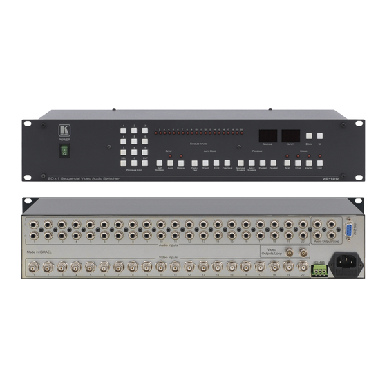
Page 7: Figure 1: Vs-120 20 X 1 Sequential Video Audio Switcher
Overview Figure 1: VS-120 20 x 1 Sequential Video Audio Switcher KRAMER: SIMPLE CREATIVE TECHNOLOGY... -
Page 8: Table 1: Front Panel Features And Functions Of The Vs-120
Overview Table 1: Front Panel Features and Functions of the VS-120 Feature Function POWER Switch Illuminated switch for turning the unit ON or OFF PROGRAM KEYS Buttons Use to set the values for the Machine Number, Input Number or Dwell Time... -
Page 9: Installing The Vs-120 In A Rack
Installing the VS-120 in a Rack Installing the VS-120 in a Rack This section describes how to install the VS-120 in a rack. Before Installing in a rack How to Rack Mount Before installing in a rack, be sure that the environment is... -
Page 10: Connecting The Vs-120
4. Connect the power cord to the mains electricity (not shown in Figure 2). Figure 2: Connecting the VS-120 1 Switch OFF the power on each device before connecting it to your VS-120. After connecting your VS-120, switch on its power and then switch on the power on each device... -
Page 11: Controlling The Vs-120
Controlling the VS-120 Controlling the VS-120 Operate the VS-120 via the front panel buttons. You can also control the VS-120 using the: RS-232 port (see section 6.1) RS-485 port (see section 6.2) Controlling via the RS-232 Port The VS-120 can be operated via PC, touch screen, or serial controller by means of serial commands transmitted through the RS-232 port. -
Page 12: Setting The Self Address
A PC that connects via its RS-232 interface to a master VS-120 that connects up to 98 slave units through its RS-485 interface If connecting a master VS-120 to an RS-232 port in a PC, first follow the steps in section 6.1. -
Page 13: Operating The Vs-120
PC, or other serial controller (see section 7.4) Operating the VS-120 as a Switcher The VS-120 operates as a 20 x 1 switcher when set to Manual mode. Any of the 20 inputs can be individually selected and routed to the output. When Manual mode is selected it prevents the scanning function from operating. -
Page 14: Enabling And Disabling Inputs
Operating the VS-120 2. To optionally choose a different machine (if using a multiple unit configuration), enter the 2-digit input number on the PROGRAM KEYS pad. When the MACHINE display flashes, enter the target machine number, then press ENT. If the MACHINE display already shows the number of the required machine, you can press ENT immediately without pressing the Machine #. -
Page 15: Operating The Vs-120 As A Scanner
Operating the VS-120 Operating the VS-120 as a Scanner The VS-120 operates as a 20 input scanner when set to Auto mode. The VS-120 scans all enabled inputs, one after another, for the amount of time programmed in the Dwell Time setting and routes the input to the output. -
Page 16: Detecting Errors
Operating Multiple VS-120 Units Multiple unit configurations of the VS-120 can be created to increase the number of outputs switched or scanned. Two VS-120s can be combined to create a 40 x 1 switcher/scanner, three units can combine into a 60 x 1 switcher/scanner, and so on, up to 99 VS-120s. -
Page 17: Viewing The Configuration Of Another Machine
Operating the VS-120 unique addresses (see Figure 5). The outputs from all the machines can be tied together to create one output for the multi-unit machine. Figure 5: Multiple Unit Configuration 7.3.1 Viewing the Configuration of Another Machine The configuration of any machine can be viewed from any other machine to see which inputs are enabled or disabled. -
Page 18: Operating Using Serial Commands
Technical Specifications Operating Using Serial Commands To operate your device using serial commands, install Kramer' s control software (K-Router) that can be downloaded from the Kramer Electronics Web site For an explanation of the RS-232 protocol and all serial commands, see section 10. -
Page 19: Hex Table
Hex Table Hex Table Table 4 lists the Hex values for the VS-120 (see section 10 for more detail): Table 4: VS-120 Hex Table Inputs Switch Commands Inputs Switch Commands (Hex) (Hex) 40 80 8B IN 1 40 80 81... -
Page 20: Table 5: Instruction Codes For Vs-120 Protocol
For example, to connect input 17 to output, the DATA should be 17( hex ). Byte 3, bit 7 must be 1. Table 5: Instruction Codes for VS-120 Protocol Note: All values in the table are hex, unless otherwise stated. - Page 21 RS-232 Communication Protocol for the VS-120 EXAMPLES FOR USING THE PROTOCOL: 1) To connect input 8 in machine 2 to the output, set the bytes as below: Byte 1 – 40(hex) + COMMAND = 40 + 00 = 40(hex). Byte 2 – 80(hex) + ADDRESS(hex) = 80 + 02 = 82(hex).
- Page 23 For the latest information on our products and a list of Kramer distributors, visit our Web site: www.kramerelectronics.com where updates to this user manual may be found. We welcome your questions, comments and feedback. Safety Warning: Disconnect the unit from the power supply before opening/servicing.
Need help?
Do you have a question about the VS-120 and is the answer not in the manual?
Questions and answers