Table of Contents
Advertisement
Quick Links
Advertisement
Table of Contents

Subscribe to Our Youtube Channel
Related Manuals for Kramer VS-41HD


Summary of Contents for Kramer VS-41HD
-
Page 1: User Manual
Kramer Electronics, Ltd. USER MANUAL Model: VS-41HD 4x1 HD/SD-SDI Switcher / DA... -
Page 2: Table Of Contents
Kramer Protocol 2000 Figures Figure 1: VS-41HD 4x1 HD/SD-SDI Switcher / DA Figure 2: Connecting the VS-41HD 4x1 HD/SD-SDI Switcher / DA Figure 3: VS-41HD SETUP Dipswitches Figure 4: Connecting a PC without using a Null-modem Adapter Figure 5: Controlling via RS-485 (for example, using an RC-3000) - Page 3 Table 1: Front Panel VS-41HD 4x1 HD/SD-SDI Switcher / DA Table 2: Rear Panel VS-41HD 4x1 HD/SD-SDI Switcher / DA Table 3: Machine # DIP-switch Settings Table 4: Technical Specifications of the VS-41HD 4x1 HD/SD-SDI Switcher / DA Table 5: Protocol Definitions Table 6: Instruction Codes for Protocol 2000...
-
Page 4: Introduction
GROUP 7: Scan Converters and Scalers; GROUP 8: Cables and Connectors; GROUP 9: Room Connectivity; GROUP 10: Accessories and Rack Adapters; GROUP 11: Sierra Products 2 Download up-to-date Kramer user manuals at http://www.kramerelectronics.com 3 The complete list of Kramer cables is on our Web site at http://www.kramerelectronics.com... - Page 5 Getting Started HD/SD SDI Camera HD SDI Camera HD SDI Camera SDI VTR HD/SD SDI Display 1 HD/SD SDI Display 2 KRAMER: SIMPLE CREATIVE TECHNOLOGY...
-
Page 6: Overview
Tri-level Genlock input according to SMPTE RP-168 • Front panel locking, and an OFF button to disconnect the output The VS-41HD is housed in a 19" 1U rack mountable enclosure and is fed from a 100-240 VAC universal switching power supply. It can be controlled... -
Page 7: Figure 1: Vs-41Hd 4X1 Hd/Sd-Sdi Switcher / Da
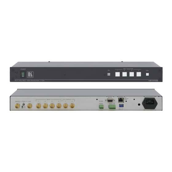
Your VS-41HD 4x1 HD/SD-SDI Switcher / DA Figure 1: VS-41HD 4x1 HD/SD-SDI Switcher / DA KRAMER: SIMPLE CREATIVE TECHNOLOGY... -
Page 8: Table 1: Front Panel Vs-41Hd 4X1 Hd/Sd-Sdi Switcher / Da
Your VS-41HD 4x1 HD/SD-SDI Switcher / DA Table 1: Front Panel VS-41HD 4x1 HD/SD-SDI Switcher / DA Feature Function IR Receiver The red LED is illuminated when receiving signals from the infra-red remote control transmitter POWER Switch Illuminated switch for turning the unit ON or OFF... -
Page 9: Installing On A Rack
5. The machine is earthed (grounded) in a reliable way power and is connected only to an electricity socket with • If you are using a Kramer rack grounding. Pay particular attention to situations where adapter kit (for a machine that is not electricity is supplied indirectly (when the power cord 19"), see the Rack Adapters user... -
Page 10: Connecting Your Vs-41Hd 4X1 Hd/Sd-Sdi Switcher / Da
, connect a remote contact closure switch (see section 6.6) 7. Connect the power cord 1 Switch OFF the power on each device before connecting it to your VS-41HD. After connecting your VS-41HD, switch on its power and then switch on the power on each device... -
Page 11: Dipswitch Settings
Connecting Your VS-41HD 4x1 HD/SD-SDI Switcher / DA Figure 2: Connecting the VS-41HD 4x1 HD/SD-SDI Switcher / DA 6.1 Dipswitch Settings By default, all dipswitches are set to OFF. Figure 3 illustrates the VS-41HD dipswitches: 1 2 3 4 Figure 3: VS-41HD SETUP Dipswitches... -
Page 12: Setting The Machine Id Dipswitches
To connect a PC to the VS-41HD unit, using the Null-modem adapter provided with the machine (recommended): • Connect the RS-232 DB9 rear panel port on the VS-41HD unit to the Null-modem adapter and connect the Null-modem adapter with a 9-... -
Page 13: Controlling Via The Rs-485 Port
VS-41HD units. (If using shielded twisted pair cable, the shield is usually connected to the “G” (Ground) PIN of the first unit). 2. Set the first VS-41HD unit as MACHINE # 1 and the following seven VS-41HD units as MACHINE # 2 to MACHINE # 8, according to... -
Page 14: Switching Two Genlocked Video Signals
6.5.1 Connecting the ETHERNET Port directly to a PC (Crossover Cable) You can connect the Ethernet port of the VS-41HD to the Ethernet port on your PC, via a crossover cable with RJ-45 connectors. This type of connection is recommended for identification of the factory default... -
Page 15: Figure 6: Local Area Connection Properties Window
Connecting Your VS-41HD 4x1 HD/SD-SDI Switcher / DA 4. Select Properties. The Local Area Connection Properties window appears. 5. Select the Internet Protocol (TCP/IP) and click the Properties Button (see Figure Figure 6: Local Area Connection Properties Window 6. Select Use the following IP address, and fill in the details as shown in Figure 7. -
Page 16: Connecting The Ethernet Port Via A Network Hub (Straight-Through Cable)
6.5.2 Connecting the ETHERNET Port via a Network Hub (Straight- Through Cable) You can connect the Ethernet port of the VS-41HD to the Ethernet port on a network hub or network router, via a straight-through cable with RJ-45 connectors. 6.5.3 Configuring the Ethernet Port After connecting the Ethernet port, you have to install and configure it. -
Page 17: Operating The Vs-41Hd
1 For details of how to route an input to an output using the REMOTE connector, see section 2 Nevertheless, even though the front panel is locked you can still operate via RS-232 or RS-485, as well as via the Kramer... -
Page 18: Technical Specifications
Table 4 includes the technical specifications: Table 4: Technical Specifications of the VS-41HD 4x1 HD/SD-SDI Switcher / DA INPUTS: 4 SDI SMPTE-259M, 292M, 344M serial video, 75 ohms on BNC connectors 1 GENLOCK 75Ω / Hi-Z on looping BNC connectors, bi level, Tri level inputs... -
Page 19: Kramer Protocol 2000
Kramer Protocol 2000 Kramer Protocol 2000 The VS-41HD is compatible with Kramer’s Protocol 2000 (version 0.46) (below). This RS-232/RS-485 communication protocol uses four bytes of information as defined below. For RS-232, a null-modem connection between the machine and controller is used. The default data rate is 9600 baud, with no parity, 8 data bits and 1 stop bit. -
Page 20: Table 6: Instruction Codes For Protocol 2000
Kramer Protocol 2000 Table 6: Instruction Codes for Protocol 2000 Note: All values in the table are decimal, unless otherwise stated. INSTRUCTION DEFINITION FOR SPECIFIC INSTRUCTION NOTE DESCRIPTION INPUT OUTPUT RESET VIDEO SWITCH VIDEO Set equal to video input Set equal to video output which is... - Page 21 NOTE 16 - The reply to the “REQUEST WHETHER PANEL IS LOCKED” is as in NOTE 4 above, except that here the OUTPUT is assigned with the value 0 if the panel is unlocked, or 1 if it is locked. KRAMER: SIMPLE CREATIVE TECHNOLOGY...
- Page 22 EXCLUSION OF DAMAGES The liability of Kramer for any effective products is limited to the repair or replacement of the product at our option. Kramer shall not be liable for: 1. Damage to other property caused by defects in this product, damages based upon inconvenience, loss of use of the product, loss of time, commercial loss;...
- Page 23 For the latest information on our products and a list of Kramer distributors, visit our Web site: www.kramerelectronics.com, where updates to this user manual may be found. We welcome your questions, comments and feedback. Safety Warning: Disconnect the unit from the power supply before opening/servicing.
Need help?
Do you have a question about the VS-41HD and is the answer not in the manual?
Questions and answers