Table of Contents
Advertisement
Quick Links
INTRODUCTION
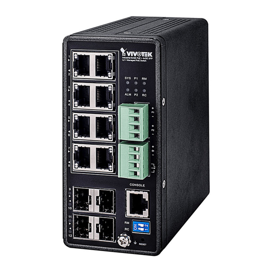
The AW-IHT-1271 managed switch supports 8x GbE PoE+, 4x GbE SFP, and 1x RJ45 console port. It is IEEE 802.3at/
af compliant and delivers the real full-load output of 240W on 8 PoE ports (30W per port). This industrial L2+ managed
switch also features a wide operating temperature range from -40ºC to 75ºC for harsh environment.
PACKAGE CONTENTS
* 1x PoE switch
* 1x DB9F-RJ45 console cable
IMPORTANT:
1. Install the converter in a ventilated and dry place that is free of electromagnetic source, vibration, moisture, and dust.
2. Make sure the ventilation openings on the converter are not blocked.
3. Use fiber optic cables and transceiver compliant with the following: Multi-mode: 50/125um, 62.5/125um, 850nm;
Single-mode): 9/125um ,1310nm.
4. DC input (48~57VDC). Follow the printed polarity for V+, V-, and Ground.
CONNECTION
10/100/1000
RJ45 ports
100/100
SFP ports
Ring Master and Rapid Chain LEDs
LED
Color
State
RM
Green On
(Ring Master)
Amber On
-
Off
RC
Green On
(Rapid Chain)
Amber On
Blinking Error, there is no correspondent Rapid Chain switch found.
-
Off
AW-IHT-1271 Industrial L2+ Managed GbE PoE+ Switch
Quick Installation Guide
* 1x Quick Installation Guide
* 1x DIN rail bracket
1. Pull out the 4-pin terminal block.
2. Connect power wires to V+, and V-.
3. Connect SFP transceivers to the fiber port.
4. install the 4-pin terminal block.
NOTE: Digital output (relay): 24VDC/1A. Digital input: level 0(Low) -> 0V to 6V,
level 1(High) -> 10V to 24V.
System LED
Power1 LED
Ring Master LED
Rapid Chain LED
Power2 LED
Alarm LED
DC 54V power input
Digital input
Digital output relay
Console port
Dip Switch (Ring Settings)
Ground screw
Description
Ring Master has been detected.
Ring Member has been detected.
Disabled.
Rapid Chain has been detected (Active path).
Rapid Chain has been detected (Backup path).
Disabled.
* 2x 4-pin terminal block
DEFAULTS
IP Address
DHCP client
Subnet Mask
255.255.255.0
User Name
admin
Password
admin
Power LEDs
LED
Color
State Description
Power1
Green On
Powered on correctly.
Off
Not receiving power from power1.
Power2
Green On
Powered on correctly.
Off
Not receiving power from power1.
System LED
LED
Color
State Description
System
Green On
Switch is ready.
Off
Switch is not ready.
Alarm LED
LED
Color
State Description
Alarm
Red
On
Abnormal state, such temperature,
voltage, or DC power, has occurred.
Off
System is normal.
Console Port Defaults
Baud rate
Stop bits
Data bits
Parity
Flow control
115200
1
8
N
none
Advertisement
Table of Contents

Related Manuals for Vivotek AW-IHT-1271


Summary of Contents for Vivotek AW-IHT-1271
- Page 1 INTRODUCTION The AW-IHT-1271 managed switch supports 8x GbE PoE+, 4x GbE SFP, and 1x RJ45 console port. It is IEEE 802.3at/ af compliant and delivers the real full-load output of 240W on 8 PoE ports (30W per port). This industrial L2+ managed switch also features a wide operating temperature range from -40ºC to 75ºC for harsh environment.
- Page 2 Control by SW DIN Rail Installation All specifications are subject to change without noice. Copyright © 2018 VIVOTEK INC. All rights reserved. VIVOTEK INC. VIVOTEK USA, INC. VIVOTEK Europe 6F, No.192, Lien-Cheng Rd., Chung-Ho, New Taipei City, 235, Taiwan, R.O.C.
Need help?
Do you have a question about the AW-IHT-1271 and is the answer not in the manual?
Questions and answers