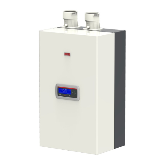
Riello Condexa PRO NA 75 P User's Information Manual
Hide thumbs
Also See for Condexa PRO NA 75 P:
- Service manual (104 pages) ,
- Installation, operation and service manual (112 pages)
Table of Contents
Advertisement
Quick Links
Condexa PRO North America
USER'S INFORMATION MANUAL
Please scan for the current version of this manual.
9
WARNING: If the information in this manual is not
followed exactly, a fire or explosion may result causing
property damage, personal injury or loss of life.
Do not store or use gasoline or other flammable
vapors and liquids or other combustible materials in
the vicinity of this or any other appliance. To do so
may result in an explosion or fire.
What to do if you smell gas:
- Do not try to light any appliance;
- Do not touch any electrical switch; do not use any
phone in your building;
- Immediately call your gas supplier from a neighbor's
phone. Follow the gas supplier's instructions;
- If you cannot reach your gas supplier, call the fire
department.
Installation and service must be performed by a
qualified installer, service agency or the gas supplier.
This manual should be maintained in legible
condition and kept adjacent to the boiler or in a safe
place for future reference.
Condexa PRO NA 75 only
Advertisement
Table of Contents

Related Manuals for Riello Condexa PRO NA 75 P


Summary of Contents for Riello Condexa PRO NA 75 P
- Page 1 WARNING: If the information in this manual is not followed exactly, a fire or explosion may result causing property damage, personal injury or loss of life. Do not store or use gasoline or other flammable vapors and liquids or other combustible materials in the vicinity of this or any other appliance.
-
Page 2: Table Of Contents
1 GENERAL INFORMATION . . . . . . . . . . . . . . . . . . . . . . . . . . . . . 3 Condexa PRO NA 75 P 20142594 Key to symbols. -
Page 3: General Information
− The boiler must only be used for its designated purpose, ob- STOP! = Identifies actions that you MUST NOT do. serving the Installation Instructions. − Only use the boiler in combination and with the accesso- ries and spare parts listed in the Riello Condexa spare parts 2 WARNING catalog. − Other combinations, accessories and consumables must only be used if they are specifically designed for the intend- 2.1 General Safety Information... -
Page 4: Unpacking The Product
UNPACKING THE PRODUCT 3 UNPACKING THE PRODUCT On receipt of your boiler it is suggested that you visually check for FOR YOUR SAFETY external damage to the shipping package. If the package is damaged, make a note to that effect on the Bill of READ BEFORE OPERATING Lading when signing for the shipment. -
Page 5: Introduction
INTRODUCTION 4 INTRODUCTION WARNING: The triggering of safety devices indicates the mal- function of a potentially hazardous situation. Therefore, contact The Condexa PRO NA it is a condensing, pre-mixed thermal mod- a service agency immediately. After a brief pause, it is possible ule consisting in a modulating thermal element. -
Page 6: System Layout
INTRODUCTION 4.1 System layout Condexa PRO NA 75 P Flue gas exhaust connection Exhaust flue temperature sensor Gas valve Combustion chamber PCB (printed control board) Flue check valve Drain cock LWCO/Minimum Water Pressure Switch (set to 7 psi/0.5 bar) 10 Pump with integrated check valve... - Page 7 INTRODUCTION Condexa PRO NA 117 P Flue gas exhaust connection Exhaust flue temperature sensor Combustion chamber PCB (printed control board) Flue check valve Drain cock LWCO/Minimum Water Pressure Switch (set to 7 psi/0.5 bar) Pump with integrated check valve 10 Power switch Central heating return 12 Gas supply 13 Central heating supply 14 Condensate drain connection...
-
Page 8: Control Panel
INTRODUCTION 4.2 Control panel CONTROL PANEL AND SYMBOLS Backlit display (4 13/16" x 1 1/2" / 255mm x 80mm) RESET key: restores normal operations after a safety lock-out MENU key: switches on the main menu ESC key: in menu navigation, it enables you to exit a menu item and go back to the previous one 5 - 9 Navigation keys ◄, ▼, ●, ►, ▲... -
Page 9: Before Switching On
INTRODUCTION 4.3 Before switching on 4.5 Filling the Condensate System WARNING: Before starting the boiler, the user must be correctly in- The condensate system must be filled with water according to the structed by the installer, on how to operate the boiler, in particular: Section "Preparation for the condensate drain". −... -
Page 10: Initial Startup
INTRODUCTION 4.7 Initial startup Confirm with the ● button and select "Date and Time " with the ▲ / ▼ buttons − Switch the system's power switch to the ON position and the boiler's master switch to (I). General Settings “ ” Language “... -
Page 11: Password Access
INTRODUCTION To change the way in which date and time are displayed, it is possi- − The system will now ask you to enter a password (the pass- ble to change the following characteristics by accessing the "Display word is required for boiler settings only): Parameters"... -
Page 12: Setting The Heating Parameters And Outdoor Reset
INTRODUCTION 4.10 Setting the heating parameters and outdoor reset The parameters regulating such temperature are: Par. Description Parameter 1 establishes the boiler's various heating operation modes. Sets the desired supply temperature with heating mode. Active for the heating mode Par. 1 = 0 or 3 Mode 0 Limits the minimum value that can be assigned to the (Operation with a room thermostat/heat demand and fixed heating... - Page 13 INTRODUCTION Mode 2 (Working on climatic mode and controlled by a room/heat demand Supply Temp. thermostat, variable set point according to the outdoor tempera- °F (°C) ture) Tset max °F (°C) Par. 24 In this case the boiler operates with a set-point defined by the climatic curve (which can be set in the same way as described in Par.
- Page 14 INTRODUCTION Mode 3 Mode 4 (Continuous fixed set-point operation and controlled by room/heat (Set-point adjustment based on a 0-10V analog input) demand thermostat) In this mode the fixed set-point is adjusted in the same way as de- The parameters that control this mode are the following: scribed for Mode 0. The difference consists in the fact that the de- Par. Description mand is always active and the set-point is decreased by the value defined parameter 28 when the room/heat demand thermostat's...
-
Page 15: Setting The Domestic Hot Water Parameters
INTRODUCTION 4.11 Setting the domestic hot water parameters − Press the ● button to confirm. Parameter 35 defines the various operation modes of the boiler for Domestic Hot Water (DHW) DHW production “ ” DHW Setpoint 113.0 °F Mode 0 “ ” “ ” (No production of domestic hot water) In this mode the boiler will work only for the heating circuit (see section "Setting the heating parameters and outdoor reset") Mode 1 −... -
Page 16: Scheduled Program
INTRODUCTION 4.12 General Safety Information Priority setting Parameter 42 sets the priorities between the DHW and CH circuit. WARNING: Water temperatures over 125°F (52°C) can cause in- Four modes are available: stant severe burns or death from scalds. Time: timed priority between the two circuits. In the event of a simultaneous demand, initially the domestic hot water circuit When supplying general purpose hot water, the recommended ini- is made to operate for a number of minutes equal to the value... -
Page 17: Electronic Control
INTRODUCTION 4.14 Electronic control The electronic control interface menu is multi-level. Navigation between the various levels is shown in the figures below. Level 0 displays the Home Screen (Home). Level 1 displays the Main Menu screen. The subsequent levels are activated depending on avail- able sub-menus. For the full layout, see section "Control panel". For how to access and change the parameters, see the picture on the next page. -
Page 18: Menu Structure
INTRODUCTION 4.14.1 Menu structure... - Page 19 INTRODUCTION...
- Page 20 INTRODUCTION...
- Page 21 INTRODUCTION...
- Page 22 INTRODUCTION...
- Page 23 INTRODUCTION...
-
Page 24: Parameters' List
INTRODUCTION 4.14.2 Parameters' list Parameters are listed base on the reference menu. Reference Menu Boiler parameters menu System cascade settings menu Nr. dis- Default Access Menu Par. No. played Description Range Category setting type Display CH set- Defines the desired supply temperature Par. 23 - 158 (70) °F (°C) Heating... -
Page 25: Error List
INTRODUCTION 4.15 Error List 4.15.2 Temporary Errors When a display has a technical fault, an error code appears that will Error Description enable the maintenance operator to identify the possible cause. WD_ERROR_RAM Internal software error WD_ERROR_ROM Internal software error WARNING: If an error persists after resetting the boiler once, contact a qualified service agency to repair the boiler. Do not WD_ERROR_STACK Internal software error... -
Page 26: How To
HOW TO 5 HOW TO 5.2 How to temporary or short-term shut-down In the event of a temporary or short-term shut-down (e.g. due to 5.1 How to increase the system pressure holidays), proceed as follows: − Press the MENU button and select "Time Schedule" with the −... -
Page 27: How To Prepare For Extended Periods Of Shut-Down
HOW TO 5.3 How to prepare for extended periods of shut- 5.4.1 How to fill down − Make sure the drain cock (1) is closed before you start filling the system Long periods of inactivity of the thermal module require the follow- ing operations to be carried out: − turn the main switch of the boiler and the main system switch to "off"... -
Page 28: What If
WHAT IF 6 WHAT IF 6.1 What if i suspect a gas leak If you suspect a gas leak, turn off the gas supply at the gas meter and contact your installer or local gas supplier from outside of the building. If you require further advice please contact a qualified Service Technician. -
Page 29: Maintenance
MAINTENANCE 7 MAINTENANCE 7.2 Cleaning and removing internal components Before any cleaning operation, disconnect the electrical power 7.1 Suggested minimum maintenance schedule supply by switching the main system switch to "off”. Regular service by a qualified service agency and maintenance must be performed to ensure maximum operating efficiency. -
Page 30: Service Reminder" Function
MAINTENANCE 7.3 "Service reminder" function − Loosen the clamp (2), detach the condensate drainage cor- rugated tube (3), remove the siphon and remove it using the two screw plugs (4) The boiler is equipped with a function that reminds the user of the −... -
Page 31: Commissioning Log For The Appliance
COMMISSIONING LOG FOR THE APPLIANCE 8 COMMISSIONING LOG FOR THE APPLIANCE NOTE: Please complete a separate log for each appliance. Home owner/operator: Last name, first name Number, Street Telephone/fax ZIP code, town System installer: Order number: Appliance type FD (Date of manufacture): Date commissioned: �... - Page 32 COMMISSIONING LOG FOR THE APPLIANCE Modified service functions: (select the modified service functions and enter the values here). Example: Vent Length Parameter changed from 1 to 2 Heating control: Gas type setting (par 98 “Gas Type”) � NG | � LPG CH set point (par.
-
Page 33: Commonwealth Of Massachusetts
COMMONWEALTH OF MASSACHUSETTS 9 COMMONWEALTH OF MASSACHUSETTS b) EXEMPTIONS: The following equipment is exempt from 248 CRM 5.08(2)(a) 1 through 4: − The equipment listed in Section 10 entitled “Equipment Not 9.1 Important instructions for the commonwealth of Required To Be Vented” in the most current edition of NFPA 54 as adopted by the board;... -
Page 34: Limited Warranty - Terms And Conditions
TEN (10) YEAR WARRANTY OF PRIMARY and SECONDARY PLATE HEAT EX- CHANGERS GENERAL NOTE Riello warrants that the heat exchanger(s) of the boiler shall be free This limited warranty is provided by Riello Canada Inc. ("Riello") the from leakage, thermal shock and condensate corrosion, and shall... - Page 35 Written permission is required for the return of any parts or equip- ment and any such return must be made on the basis of trans- The obligations of Riello here under shall also be subject to the fol- portation charges prepaid. Shipments may be refused unless prior lowing terms and conditions;...
- Page 36 RIELLO S.p.A. Via Ing. Pilade Riello, 7 37045 - Legnago (VR) www.rielloboilers.com Riello North America 2165 Meadowpine Blvd. Mississauga, ON L5N6H6 CANADA Technical Support Hotline: 1.800.474.3556 Professional Resources: www.riello.com The manufacturer strives to continuously improve all products: appearance, dimensions, technical specifications, standard equipment and ac- cessories are therefore liable to modification without notice.
Need help?
Do you have a question about the Condexa PRO NA 75 P and is the answer not in the manual?
Questions and answers