
Related Manuals for Meyra 9.072


Summary of Contents for Meyra 9.072
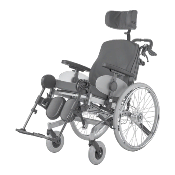
- Page 1 Multifunction-Wheelchair Model 9.072 Operating manual W e m o v e p e o p l e .
-
Page 2: Table Of Contents
Contents Meaning of the applied markers Introduction List of models Indications Acceptance Specifications Adjustment Reinstallment Life span Overview Brake Pressure brake - user Locking the brakes Releasing the brakes Service brake Drum brake for accompanying persons Function as operating brakes Leg supports Lower leg support Footplates... - Page 3 Arm supports Removing the arm support Inserting the arm support Adjustment of the armrest height Depth adjustment of the arm support cushions Repositioning the arm support cushion Back support with angle adjustment Adjusting the angle of the back support Folding down the back support Unfolding the back support Back support upholstery Head support...
- Page 4 Maintenance Maintenance schedule Technical data Tyre pressure of pneumatic tyres Data according to ISO for model 9.072 Further technical data for model 9.072 Meaning of the symbols on the washing instruction Meaning of the labels on the wheelchair Meaning of the symbols on the type plate...
-
Page 5: Meaning Of The Applied Markers
This operating manual applies to the follow- observed under any circumstance! ing models: ☞ This symbol indicates tips and recom- Model 9.072 mendations [ ] Reference to a picture number INDICATIONS ( ) Reference to a function element within a picture. -
Page 6: Specifications
SPECIFICATIONS Use only the handrims on the drive wheels to propel your wheelchair. The wheelchair was developed for adults You must not let yourself be carried in your and adolescents. The wheelchair solely wheelchair by having the wheelchair lifted serves to transport one person in the seat from the floor. -
Page 7: Reinstallment
REINSTALLMENT The wheelchair is suited for reinstallment. With the building block system the wheel- chair can be fit to accommodate different handicaps body sizes. Before reimplemen- tation the wheelchair is to undergo a com- plete inspection. ☞ Hygienical measures required for rein- stallment are to be carried out accord- ing to a validated hygienic plan and must include disinfection. -
Page 8: Overview
OVERVIEW The overview shows, representative for all models, the most important components of the care wheelchair. Pos. Description (8) Footplate (1) Push handle (9) Steering wheel (2) Pushing bar (10) Type plate (3) Head support (11) Brake lever – pressure brake (4) Back support (12) Locking knob –... -
Page 9: Brake
BRAKE Arrange an immediate repair of the brakes by your specialist workshop if the braking performance reduces. By locking the brakes with the brake lever (1), the wheelchair is secured against rolling away unintentionally (parking brake). Depending on the version, the wheelchair can be equipped with pressure brakes (2) or with drum brakes (3). -
Page 10: Drum Brake For Accompanying Persons
Drum brake for accompanying persons The drum brake is activated by the accom- panying person through the brake levers (1). Function as operating brakes Use both brake levers evenly and only light- ly in order to achieve a controlled decelera- tion of the wheelchair. -
Page 11: Leg Supports
LEG SUPPORTS Before any actions on the leg supports the wheelchair is to be secured against unintentional rolling motions. ☞ Therefore observe chapter Brake on page 9. Lower leg support For entry into, exiting the wheelchair or "scuttling" (forward motion of the wheel- chair with the feet) the footplates (1) are to be folded up and the calf pads (2) folded outward in driving direction [3]. -
Page 12: Leg Support Upper Part
LEG SUPPORT UPPER PART The upper leg support with an inserted lower leg support is termed leg support [1]. Turning the leg supports to the side Leg supports turned to the side are re- leased automatically and can easily come off. -
Page 13: Swivelling In The Leg Supports
Swivelling in the leg supports For inward swivelling, let the leg supports swivel forward until the lock audibly engag- es [1]. ☞ After audibly swivelling the leg sup- ports inward check the respective lock- ing device. ☞ Afterwards observe the chapter Lower leg support on page 11. -
Page 14: Mechanically Height-Adjustable Leg Supports
Mechanically height-adjustable leg supports Never put the free hand into the adjust- ment mechanism. Have the leg support secured by an accompanying person against unintentionally falling down. Do not let the leg support drop on its own weight. – Danger of injury! Lifting/lowering the leg support Before lifting/lowering relieve the leg sup- port by an accompanying person by slightly... -
Page 15: Adjusting The Height Of The Footplate
Adjusting the height of the footplate Loosen the clamping screw (1) to adjust the height. ☞ Loosen the clamping screw (1) so far that no damage to the coating occurs during the adjustment. ☞ Observe the maximum extension mark (2). Telescope the footplate to the desired height and then retighten the clamping screw (1). -
Page 16: Arm Supports
ARM SUPPORTS Do not use the arm supports [1] to lift or carry the wheelchair. Do not drive without the arm supports. No not grab between the frame and arm support. – Danger of squashing! When the wheelchair is being pushed by an attendant the user is to place his hands onto the arm cushions or in his lap and not at the sides between body and... -
Page 17: Adjustment Of The Armrest Height
Adjustment of the armrest height Before loosening the clamping screws (2) secure the arm support against falling down with your hand. – Danger of jam- ming! The maximum arm support height has been reached when the marking on the square tube is visible. First loosen the clamping screw (1) of the height stopper before adjusting the height of the arm support. -
Page 18: Back Support With Angle Adjustment
BACK SUPPORT WITH AN- GLE ADJUSTMENT Before any actions on the back supports the wheelchair is to be secured against unintentional rolling motions. ☞ Therefore observe chapter Brake on page 9. Adjusting the angle of the back support The angle of the back support [1] is contin- uously adjustable through the gas pressure spring. -
Page 19: Folding Down The Back Support
Folding down the back support Fold open the safety latch (2) first for folding over the back support [1], then remove the pin (3). ☞ All the while hold the back support in position with one hand on the push bar or handle in order to prevent it from tilt- ing over to the back. -
Page 20: Back Support Upholstery
Back support upholstery The back support upholstery is attached to the back shell with velcro straps [1] and can be pulled off for cleaning or maintenance [2]. ☞ The cover can be removed with the zip- per for washing. ☞ Therefore observe the label with the washing instruction (3). -
Page 21: Head Support
HEAD SUPPORT A headrest mounted to the wheelchair serves as a support for the posture of the head, not as a transport security. The upper edge of the adjustable head support [1] should always be close to the back of the head at about eye level. ☞... -
Page 22: Seat Inclination
SEAT INCLINATION Before any actions on the seat unit the wheelchair is to be secured against unin- tentional rolling motions. ☞ Therefore observe chapter Brake on page 9. The seat unit is continuously tiltable through the gas pressure spring [1]. Adjustment of seat inclination Activate the left lever (2) on the push handle for continuous adjustment of the seat unit. -
Page 23: Rising Aid
RISING AID Before using the rising aid, secure the wheelchair and fold up the footplates. ☞ Therefore observe chapter Brake on page 9. The seat is angled forward for the stand-up aid [1] (negative seat inclination). ☞ The negative seat angle setting serves as support for getting up when the wheelchair is standing. -
Page 24: Wheels
WHEELS Drive wheels After inserting the drive wheel the locking button (2) must stick a couple of millime- tres out of the wheel nut. The drive wheels are supported on a quick release axle [1] and can be removed resp. at- tached without tools. -
Page 25: Handrims
Handrims Take care that you do not squash your hands when driving narrow routes, e.g. building entrances, doorways, etc.. – Dan- ger of injury to the hands! Replace damaged handrims immediately in order to prevent your hands being in- jured by such handrims and in order to al- ways have full control of your wheelchair. -
Page 26: Retaining Strap
RETAINING STRAP Make sure that no objects are trapped be- tween belt and the body! The retaining strap is not part of the re- taining system for the wheelchair and/or the driver during transport in motor vehi- cles. The retaining strap [1] is screwed onto the respective lateral back brace with latches. -
Page 27: Folding/Unfolding
FOLDING/UNFOLDING The wheelchair is to be secured before folding/unfolding. ☞ Therefore observe chapter Brake on page 9. Folding the wheelchair Proceed as follows to fold the wheelchair [2]: In necessary remove the seat cushion. 2. Remove or swivel away the leg sup- ports. -
Page 28: Basic Safety Information
BASIC SAFETY Accompanying person INFORMATION The accompanying person must be made aware of all possible danger situation before Do not insert fingers into open frame the start of his/her supportive involvement. tubes (for example after removing the The parts of your wheelchair that are held arm supports, leg supports or support onto by the accompanying person are to be castors). -
Page 29: Crossing Obstacles
Crossing obstacles by changing the position of their upper body. After overcoming obstacles, the previous- The accompanying person should be aware ly removed support castors need to be that the control of the wheelchair requires reattached. more strength on a downward slope/ hills Each crossing of obstacles involves a risk! than on a level driving surface and that Even flat obstacles (e.g. -
Page 30: Loading The Wheelchair
39. wheelchair! ☞ Observe the guideline < Safety with Before lifting, the wheelchair is to be se- Meyra-wheelchairs, also during transport cured against unintentional rolling mo- in motor vehicles >! – This document tions! and further information are available ☞... -
Page 31: Driving On Public Highways
Further information to cleaning can be – Reflectors on the back support found in the < Infozentrum > on our website: – Reflectors on the drive wheels. < www.meyra.com >. With limited visibility and especially in the Finish dark we recommend to mount active light-... -
Page 32: Disposal
☞ In doing so the manufacturers instruc- tions are to be observed. DISPOSAL The disposal must comply with the respec- tive national law. Please enquire about local disposal arrange- ments at your municipal authority. MAINTENANCE An incorrect or neglected cleaning and maintenance of the wheelchair results in a limitation of the product liability. -
Page 33: Maintenance Schedule
Maintenance schedule WHEN WHAT REMARK Before starting out General Carry out test yourself or with a helper. Test for faultless operation. Before starting out Test brakes for fault- Carry out test yourself or less operation with a helper. The locked wheels should Activate brake lever to the not be able to turn un- limit. - Page 34 WHEN WHAT REMARK Every 2 weeks Check air pressure of Carry out test yourself or (depending on distance the tyres with a helper. covered) Use a tyre gauge. Tyre filling pressure: ☞ View Tyre pressure of pneumatic tyres page 35. Every 8 weeks Check tyre profile Carry out visual check...
-
Page 35: Technical Data
TECHNICAL DATA Tyre pressure of pneumatic tyres Maximum tyre pressure is printed on the All data given in the < Technical data > re- tyres on each side. fers to the standard version. Full tyre pressure – drive wheel The overall length depends on the position Standard: and size of the drive wheels. -
Page 36: Data According To Iso For Model 9.072
Data according to ISO for model 9.072 Overall length with leg support 1180 mm 1740 mm Overall width 620 mm 690 mm Overall dimensions – kg 198 kg User weight (incl. additional load) (SW 43/46) – kg 130 kg User weight (incl. additional load) (SW 48/51) –... -
Page 37: Further Technical Data For Model 9.072
Further technical data for model 9.072 Length without leg support 910 mm 910 mm Overall height 1040 mm 1130 mm Seat cushion thickness 70 mm 70 mm Length without leg supports, drive wheels (Support castors are removed or swivelled under-... -
Page 38: Meaning Of The Symbols On The Washing Instruction
Meaning of the symbols on the washing instruction (the symbols correspond to European standard) Wash as delicates with the indicated maximum temperature in °C Wash as regular laundry with the indicated maximum temperature in °C Do not bleach Not suited for the dryer Do not iron Do not dry-clean... -
Page 39: Meaning Of The Labels On The Wheelchair
Meaning of the labels on the wheelchair Attention! Read the operating manuals and other provided documen- tation. Do not lift the wheelchair at the arm supports or leg sup- ports. Removable parts are not suitable for carrying. Lever for seat angle / tilt. Lever for angle adjustment of the back support. -
Page 40: Meaning Of The Symbols On The Type Plate
Meaning of the symbols on the type plate Manufacturer Order number Serial number Production date (Year – Calendar week) Permitted user weight max. permissible total weight Permitted axle weights Max. permissible rising gradient Max. permissible falling gradient Permitted maximum speed The product is approved as a seat within a motor vehicle The product is not approved as a seat within a motor vehicle. -
Page 41: Inspection Certificate
INSPECTION CERTIFICATE Recommended safety inspection 1st year (at least every 12 months) Vehicle data: Stamp of specialist dealer: Model: Signature: Delivery note no.: Place, date: Serial-no.(SN): Next safety inspection in 12 months Date: Recommended safety inspection 3rd year Recommended safety inspection 2nd year (at least every 12 months) (at least every 12 months) Stamp of specialist dealer:... -
Page 42: Warranty / Guarantee
WARRANTY / GUARANTEE norm specifications cannot be declared as warranty or guarantee claims. We accept legal liability for this product Attention: within the scope of or general terms and Failure to observe the instructions in conditions and warranty and the guaran- the operating manual, improperly car- tee according to our described quality ser- ried out maintenance work and, espe-... -
Page 43: Warrantee / Guarantee Section
Warrantee / Guarantee section Please fill out! Copy if necessary and send the copy to the specialist dealer. Warranty / Guarantee Model designation: Delivery note no.: SN (view type plate): Date of delivery: Stamp of the specialist dealer: Inspection certificate for transfer Vehicle data: Serial-no.(SN): Stamp of specialist dealer:... - Page 44 Your specialist dealer MEYRA GmbH Meyra-Ring 2 D-32689 Kalletal-Kalldorf +49 5733 922 - 311 +49 5733 922 - 9311 info@meyra.de www.meyra.de MEYRA 205 338 401 (Status: 2016-10) All technical modifications reserved.
Need help?
Do you have a question about the 9.072 and is the answer not in the manual?
Questions and answers