
Related Manuals for Meyra 9.050


Summary of Contents for Meyra 9.050
- Page 1 Folding Wheelchair Model 9.050 Model 3.940 Operating manual m o v e p e o p l e .
-
Page 2: Table Of Contents
Contents Introduction List of models Indications Acceptance Specifications Adjustment Life span Overview Brake Pressure brake - user Locking the brakes Releasing the brakes Service brake Drum brake for accompanying persons Function as operating brakes Locking the drum brakes Releasing the drum brakes Leg supports Calf belt Removing the calf belt... - Page 3 Arm support Swivelling up the arm support Swivelling the arm support inward Swivelling down the arm support Removing the arm support Inserting the arm support Wheels Drive wheels Quick release axle Drive wheels with pneumatic tyres Tyre damage on pneumatic tyres Back support Back support belt Fitting the back belt...
-
Page 4: Introduction
INTRODUCTION can be accessed on our website < www. meyra.com >. We thank you for the confidence you have ☞ Contact your specialist dealer when re- placed in our company by choosing a quired. wheelchair from this series. Alternatively users with visual impairments... -
Page 5: List Of Models
This operating manual applies to the follow- All products are checked for faults in the ing model: factory and packed in special boxes. Model 9.050 ☞ Note: Model 3.940. However, we request that you check the vehicle for possible transport damage immediately on receipt –... -
Page 6: Specifications
SPECIFICATIONS The wheelchair of the standard-fold- The wheelchair is universally applicable on ing-wheelchair-family, was developed for level, firm surfaces and can be used as fol- adults and adolescents. lows: – for indoors (e.g. apartment, day care), The wheelchair solely serves to transport –... -
Page 7: Adjustment
ADJUSTMENT LIFE SPAN The specialist workshop will hand out the We expect an average life span of about wheelchair to you under consideration of all 4 years for this product, as far as the product relevant safety instructions, ready for opera- is applied for its designated purpose and all tion and adjusted to your needs. -
Page 8: Overview
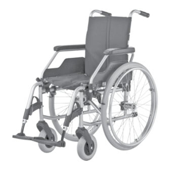
OVERVIEW The overview shows, representative for all models, the most important components of the standard-folding-wheelchair. Pos. Description (1) Push handle (8) Steering wheel (2) Back support (9) Locking lever– Arm support (3) Arm support (10) Locking knob – Quick release axle (4) Seat belt/seat cushion (11) Brake lever –... -
Page 9: Brake
BRAKE By locking the brakes with the brake lever (1), the wheelchair is secured against rolling away unintentionally (parking brake). Depending on the version, the wheelchair can be equipped with pressure brakes (2) or with drum brakes (3). ☞ Note: Therefore observe the maintenance in- structions as well as safety and general handling instructions <... -
Page 10: Pressure Brake - User
Pressure brake - user Locking the brakes To secure the wheelchair against any unin- tentional rolling, press both brake levers for- ward all the way (1). ☞ Note: It should not be possible to push the wheelchair forward when both brakes are locked. -
Page 11: Drum Brake For Accompanying Persons
Drum brake for accompanying persons The drum brake is operated by the accom- panying person by way of the brake levers (1) on the extended push handles or the pushing rod. Attention: With the drum brakes version, the ac- companying person must not lift the wheelchair on the extended push han- dles! –... -
Page 12: Leg Supports
LEG SUPPORTS Attention: Before any actions on the leg supports the wheelchair is to be secured against unintentional rolling motions. ☞ For this observe chapter Brake on page 9. Calf belt The removable calf belt (1) prevents the feet from sliding off the back of the footplates. Attention: Never drive without calf belt (except when scuttling)! –... -
Page 13: Attaching The Calf Belt
Attaching the calf belt For attachment both loops of the calf belt are to be slid over the attachment pins [1]. Length adjustment of the calf belt For length adjustment the calf belt is to be adjusted in length with help of the velcro fastener at the back. -
Page 14: Leg Support Upper Part
Leg support upper part The upper leg support with an inserted lower leg support is termed leg support. Turning the leg supports to the side For easy transfer out of/into the wheelchair as well as driving closer to a closet, bed or bathtub the leg supports can be swivelled away toward the in-/outside [1] and [2]. -
Page 15: Swivelling In The Leg Supports
Swivelling in the leg supports ☞ Note: After audibly swivelling the leg supports inward check the locking device of the respective leg support. ☞ Afterwards observe chapter Lower leg support on page 13. For inward swivelling, let the leg supports swivel forward until the locking device au- dibly engages [1]. -
Page 16: Arm Support
ARM SUPPORT The arm supports [1] are removable [2] and simultaneously serve as padded arm sup- port, clothes guard and wind protector. Attention: No not grab between the frame and arm support. – Danger of squashing! Do not lift the wheelchair using the arm supports. -
Page 17: Swivelling Up The Arm Support
Swivelling up the arm support For transfer out of/into the wheelchair the arm support can be swivelled upward [1] as well as turned behind the back support [2]. – Fold the locking lever - arm support up (3) in order to swivel up the arm support. –... -
Page 18: Removing The Arm Support
Removing the arm support For removal of the arm support [1]: 1. a) fold the locking lever up on the front and back (2). 1. b) first fold the front locking lever up (2), then swivel the arm support up and in- ward. -
Page 19: Inserting The Arm Support
Inserting the arm support ☞ Note: The tube of the arm support must lie in the guide groove on the back tube (1). 1. For attachment, insert the arm support from the top into the respective bracket and swivel it down. ☞... -
Page 20: Wheels
WHEELS Drive wheels The drive wheels are on a quick release axle [1]. ☞ If the drive wheels has too much side- ward lag or the quick release axle does not engage, contact your specialist deal- er immediately for repair. ☞... -
Page 21: Back Support
BACK SUPPORT Back support belt Fitting the back belt The tensioning of the back support (1) is ad- justable. – Pull the back belt off and fold it to the front (2). – Open the Velcro fastener of the belt (3) that you wish to adjust and close it again after adjustment. -
Page 22: Support Castors
SUPPORT CASTORS Stick-in support castors The insertable support castors can be in- serted from the back into the lower frame tubes [1]. Removing/inserting the support castors – Depress the corresponding spring but- ton (2) in order to remove/insert a sup- port castor. -
Page 23: Retaining Strap
RETAINING STRAP The retaining strap [1] is screwed with mounting links onto the back tubes. ☞ Note: The subsequent assembly of a lap re- taining strap must be carried out by a specialist workshop! Attention: The retaining strap is not part of the re- taining system for the wheelchair and/ or the driver during transport in a hand- icapped transport vehicle. -
Page 24: Transport Of People Inside A Motor Vehicle
TRANSPORT OF PEOPLE INSIDE A MOTOR VEHICLE To determine if your wheelchair is approved as a seat for transport inside a motor vehicle, please look at the type plate of your wheel- chair. Attention: Subsequently, firmly attached parts of non-original parts to your wheelchair are not approved for person transporta- tion within an HTV. -
Page 25: Maintenance Schedule
Maintenance schedule WHEN WHAT REMARK Before starting out Test brakes for fault- Carry out test yourself or less operation with a helper. Activate brake lever to the limit. The locked wheels should not be able to turn under operating condi- tions. - Page 26 WHEN WHAT REMARK Before starting out Check back support Carry out the test yourself for stability or by a helper. If deformations or cracks Check frame tubes for occur in the welding damage seams, contact a specialist workshop immediately for repairs.
-
Page 27: Safety Inspection
WHEN WHAT REMARK Every 6 months Check: View < Maintenance > in (depending on frequency document < Safety- and – Cleanness. of use) general handling instruc- – General condition. tions Mechanical and mus- cle powered wheelchairs >. Do it yourself or with the aid of a helper. -
Page 28: Technical Data
TECHNICAL DATA Tyre pressure of pneumatic tyres Maximum tyre pressure is printed on the All data given in the < Technical data > refers tyres on each side. to the standard version. Full tyre pressure – drive wheel The overall length depends on the position Standard: and size of the drive wheels. - Page 29 Model: ..........................9.050 Type plate: ............................ at the crossbrace tube Life span: ..................................4 years Dimensions Overall length with leg supports (min. / max.): ..............1020 / 1080 mm Length without leg supports (min. / max.): ................770 / 830 mm Overall width (min.
- Page 30 Transport dimensions Folding length with leg supports (min. / max.): ..............1020 / 1080 mm Folding length (without leg supports, drive wheels): ............... 750 mm (Support castors are removed or swivelled underneath the seat) Folding width: ................................280 mm Folding height: ...............................min. 960 mm Permitted inclination/slopes max.
- Page 31 Model: ..........................3.940 Type plate: ............................ at the crossbrace tube Life span: ..................................4 years Dimensions Overall length with leg supports (min. / max.): ..............1020 / 1080 mm Length without leg supports (min. / max.): ................770 / 830 mm Overall width (min.
- Page 32 Transport dimensions Folding length with leg supports (min. / max.): ..............1020 / 1080 mm Folding length (without leg supports, drive wheels): ............... 750 mm (Support castors are removed or swivelled underneath the seat) Folding width: ................................280 mm Folding height: ...............................min. 960 mm Permitted inclination/slopes max.
-
Page 33: Meaning Of The Labels On The Wheelchair
Meaning of the labels on the wheelchair Attention! Read the operating manuals and other provided documen- tation. Do not lift the wheelchair at the arm supports or leg sup- ports. Removable parts are not suitable for carrying. Attention! Readjust the brakes. Attention! Increased danger of tilting when on inclinations / slopes, es- pecially in combination with short wheel base. -
Page 34: Meaning Of The Symbols On The Type Plate
Meaning of the symbols on the type plate Manufacturer Order number Serial number Production date (Year – Calendar week) Permitted user weight Permitted overall weight Permitted axle weights Permitted rising gradient Permitted falling gradient Permitted maximum speed The product is approved as a seat within a motor vehicle The product is not approved as a seat within a motor vehicle. -
Page 35: Inspection Certificate
INSPECTION CERTIFICATE Recommended safety inspection 1st year (at least every 12 months) Vehicle data: Stamp of specialist dealer: Model: Signature: Delivery note no.: Place, date: Serial-no.(SN): Next safety inspection in 12 months Date: Recommended safety inspection 2nd year Recommended safety inspection 3rd year (at least every 12 months) (at least every 12 months) Stamp of specialist dealer:... -
Page 36: Notes
NOTES... - Page 37 NOTES...
-
Page 38: Warranty / Guarantee
WARRANTY / GUARANTEE norm specifications cannot be declared as warranty or guarantee claims. We accept legal liability for this product Attention: within the scope of or general terms and Failure to observe the instructions in the conditions and warranty and the guaran- operating manual, improperly carried tee according to our described quality ser- out maintenance work and, especially,... -
Page 39: Warrantee / Guarantee Section
Warrantee / Guarantee section Please fill out! Copy if necessary and send the copy to the specialist dealer. Warranty / Guarantee Model designation: Delivery note no.: SN (view type plate): Date of delivery: Stamp of the specialist dealer: Inspection certificate for transfer Vehicle data: Serial-no.(SN): Stamp of specialist dealer:... - Page 40 Your specialist dealer MEYRA GmbH Meyra-Ring 2 D-32689 Kalletal-Kalldorf +49 5733 922 - 311 +49 5733 922 - 9311 info@meyra.de www.meyra.de Meyra 205 338 201 (Status: 2013-10) All technical modifications reserved.
Need help?
Do you have a question about the 9.050 and is the answer not in the manual?
Questions and answers