Sign In
Upload
Download
Table of Contents
Contents
Add to my manuals
Delete from my manuals
Share
URL of this page:
HTML Link:
Bookmark this page
Add
Manual will be automatically added to "My Manuals"
Print this page
×
Bookmark added
×
Added to my manuals
Manuals
Brands
nvent Manuals
Cables and connectors
RAYCHEM BTV
Installation and maintenance manual
nvent RAYCHEM BTV Installation And Maintenance Manual
Hide thumbs
Also See for RAYCHEM BTV
:
Installation and maintenance manual
(36 pages)
1
2
Table Of Contents
3
4
5
6
7
8
9
10
11
12
13
14
15
16
17
18
19
20
21
22
23
24
25
26
27
28
29
30
31
32
33
34
35
36
37
38
39
40
41
42
43
44
45
46
47
48
page
of
48
Go
/
48
Contents
Table of Contents
Troubleshooting
Bookmarks
Table of Contents
Table of Contents
General Information
Use of the Manual
Safety Guidelines
Electrical Codes
Warranty and Approvals
General Installation Notes
Heating Cable Selection
Heating Cable Installation
Heating Cable Storage
Pre-Installation Checks
Installation
Heating Cable Components
General Component Information
Control and Monitoring
Thermal Insulation
Pre-Insulation Checks
Insulation Installation Hints
Marking
Post-Insulation Testing
Power Supply and Electrical Protection
Voltage Rating
Electrical Loading
Ground-Fault Protection
Commissioning and Preventive Maintenance
Tests
Preventive Maintenance
Test Procedures
Visual Inspection
Insulation Resistance (Megger) Test
Power Check
Fault Location Tests
Troubleshooting Guide
Installation and Inspection Records
Advertisement
Quick Links
1
Heating Cable Selection
2
Heating Cable Installation
3
Installation
Download this manual
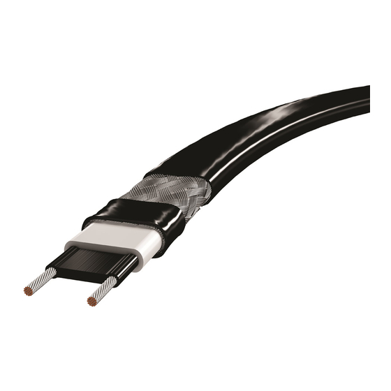
Industrial Heat Tracing
Installation and Maintenance Manual for
Self-Regulating and Power-Limiting
Heating Cable Systems
Table of
Contents
Previous
Page
Next
Page
1
2
3
4
5
Advertisement
Table of Contents
Need help?
Do you have a question about the RAYCHEM BTV and is the answer not in the manual?
Ask a question
Questions and answers
Related Manuals for nvent RAYCHEM BTV
Heating System nvent RAYCHEM BTV Installation And Maintenance Manual
Self-regulating and power limiting heating cable systems (36 pages)
Cables and connectors nvent RAYCHEM VPL Installation And Maintenance Manual
(48 pages)
nvent RAYCHEM Manual
(article)
Cables and connectors nvent RAYCHEM Installation Instructions Manual
Rayclic-le lighted end seal kit (6 pages)
Cables and connectors Nvent RAYCHEM RayClic-E Installation Instructions
Rayclic end seal kit (2 pages)
Cables and connectors nvent RAYCHEM HWT-P Installation Instructions Manual
Hwat power connection kit with end seal (6 pages)
Cables and connectors nvent Raychem RayClic Series Installation Instructions Manual
Connection system (10 pages)
Cables and connectors nvent JBS-100-A Installation Instructions Manual
Single entry power connection with junction box (24 pages)
Cables and connectors nvent Raychem CCON25-100 Installation And Operating Instructions Manual
Connection kit for conduit system (28 pages)
Cables and connectors Nvent Raychem E-100-E Manual
End seal (20 pages)
Cables and connectors nvent LENTON Instruction Sheet
(2 pages)
Cables and connectors nvent Raychem JBM-100-E Manual
Multiple entry power connection with junction box (40 pages)
Cables and connectors Nvent Raychem CCON20-100-PI Series Installation And Operating Instructions Manual
Connection kit for conduit system (40 pages)
Cables and connectors nvent Raychem GM-2CW Installation Manual
(80 pages)
Cables and connectors nvent raychem ETL-GLAND-01 Manual
(4 pages)
Cables and connectors nvent Raychem C-150-E Manual
Low profile power connection kit (28 pages)
This manual is also suitable for:
Raychem qtvr
Raychem hbtv
Raychem hqtv
Raychem xtv
Raychem hxtv
Raychem vpl
...
Show all
Raychem ktv
Table of Contents
Save PDF
Print
Rename the bookmark
Delete bookmark?
Delete from my manuals?
Login
Sign In
OR
Sign in with Facebook
Sign in with Google
Upload manual
Upload from disk
Upload from URL


Need help?
Do you have a question about the RAYCHEM BTV and is the answer not in the manual?
Questions and answers