
Subscribe to Our Youtube Channel
Related Manuals for Proteco SWING


Summary of Contents for Proteco SWING
- Page 1 Installation Manual SWING Automation system for counterweight balanced (up and over) garage doors Technical Installation Manual...
-
Page 2: Warnings And General Safety Instuctions
Use exclusively original parts by manufactured by Proteco for maintenance. Do not carry out any alteration on the components of the automatic gate. Proteco SRL will not accept liability for any components and/or additional devices used in-conjunction with the automation that has not been produced exclusively by Proteco. -
Page 3: Product Description And Intended Use
PRODUCT DESCRIPTION AND INTENDED USE Technical Specifications Il motoriduttore SWING è stato studiato per automatizzare porte da garage basculante a contrappeso di tipo residenziale. Qualsiasi altro uso da quello descritto è da considerarsi improprio e vietato. Tutti i modelli garantiscono il blocco meccanico della porta con un sistema di ingranaggi irreversibile;... -
Page 4: Installation
INSTALLATION Preliminary Checks Before the installation, to ensure correct working of the automation, please check the followings: • Make sure the door can be easily moved manually, without frictions or clinging • Check the weight, dimensions and type of the door is appropriate to this type of automation •... -
Page 5: Gear Motor Installation
Gear motor Installation Fix the base plate on the door according to the type of doors and measurements as shown here below. a) Unlock any kind of door blocking system b) Find the door’s height dimension H by door type (Fig. 1, 2 and 3). - Page 6 Installing the transmission arms 3.4.1 Installing CENTRAL transmission arms set E102/C (Optional purchase) a) Fix the transmission arms with toothed ring onto the drive shaft and fasten with the two M8x8 grub screws (Fig. 6) b) Get the L arms in to the triangle-shaped brackets with plastic ring (Fig.
- Page 7 3.4.2 Installing LATERAL transmission arms set E 102/L (Optional purchase) a) Fix the toothed ring arm onto the drive shaft and fasten it with the grub screw M8x8 (Fig. 14). In case of twin motor installation, repeat procedure on the opposte side. b) I Insert the flat arms (“swords”) 35x5 in to the toothed ring arm (Fig.15) c) Fix the flat arms (“swords”) directly to the upper pivots of...
-
Page 8: Electrical Wiring
ELECTRICAL WIRING Wire motor and limit switches as per below schemes: LIMIT SWITCHES WIRING MOTOR WIRING Verde Bianco CLOSE OPEN Marrone Marrone Nero Giallo Insert electrical cables into the control panel’s case. Please follow the control panel’s instruction manual to proceed with the correct cable wiring and programming. - Page 9 6. INSTALLING THE MANUAL RELEASE SYSTM FROM OUTSIDEE 101 (Optional) Unlock motor moving the handle. Insert the steel wire in the eyelet on the motor carter (zoom A) Get the steel wire into the black sheath. Drive the sheath and the wire to the point where the pulling system will be fixed.
-
Page 10: Release Procedure For Manual Operation
TESTING THE AUTOMATION AND START UP Power the system and proceed with a careful checking of the gear motor working, please pay particular attention to safety devices connected to the automation and to the emergency manual release systems. Place the cover on the motor and screw it. Hand over this instructions manual to the end user and demonstrate the correct use of the automation and how to release the motor for manual operation of the gate in the event of power cuts. -
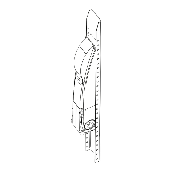
Page 11: Exploded View Drawing
EXPLODED VIEW DRAWING Proteco S.r.l. Via Neive, 77 - 12050 CASTAGNITO (CN) ITALY Tel. +39 0173 210111 - Fax +39 0173 210199 - info@proteco.net - www.proteco.net...
Need help?
Do you have a question about the SWING and is the answer not in the manual?
Questions and answers