Table of Contents
Advertisement
Advertisement
Table of Contents

Related Manuals for Proteco ACE


Summary of Contents for Proteco ACE
- Page 1 INSTALLATION MANUAL Gearmotor for swing gates...
-
Page 3: Table Of Contents
Index SAFETY INSTRUCTIONS ............................pag. 01 COMPLIANCE DECLARATION ........................... pag. 01 DESCRIPTION AND INTENDED USE ........................pag. 01 Technical data ............................pag. 02 Kit content ............................... pag. 02 Dimensions ............................. pag. 02 INSTALLATION ..............................pag. 03 Preliminary checks ..........................pag. 03 Wiring ................................ -
Page 4: Safety Instructions
ACE electromechanical gear motor for swing gates Models: ACE 3 TI, ACE 4 TI, ACE 4 REV, ACE 3 24 TI, ACE 4 24 TI ACE 4 TA, ACE 4 24 -TA Is built to be integrated into a machine or to be assembled with other machinery to crate a machine under provisions of 2006/42/EC Machinery Directive, with reference in particular to the following requirements: 1.1.2 1.1.3 1.1.5 1.2.1 1.2.2 1.2.3 1.2.6 1.3.2 1.3.4 1.3.9 1.4.1... -
Page 5: Technical Data
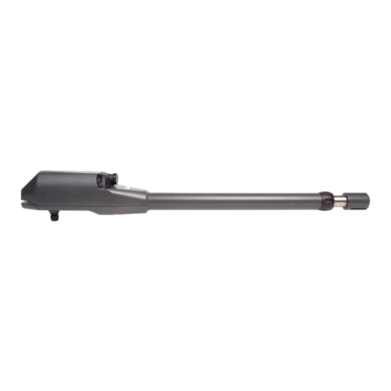
MGR1410Z Fixing pack MPE1226 MRO12Z MDAM12AB Front bracket S4 SPIA0370 Release key DIMENSIONS Ace 4 TA = 1040 mm Ace 3 = 815 mm Ace 4 = 915 mm Ace 3 = 1135 mm - Ace 4 = 1335 mm... -
Page 6: Installation
INSTALLATION Preliminary checks Before installing make sure: • The gate conditions are suitable to automate. • Weight, dimensions and gate construction are proper for the operator you intend to buy. • You have suitable mechanical ground stops. • The automated parts are in good mechanical conditions. •... -
Page 7: Establishing Rh And Lh Operator
Fig. 4 50 mm ACE TI Gate in closing position - inox pipe maximum extension: Ace 3 = 345 mm Ace 4 = 445 mm 345 mm ACE 3 TI Gate in opening position - inox pipe minimum extension 50 mm 445 mm ACE 4 TI (see picture 4). - Page 8 Fig. 8 OUTER VIEW OUTER VIEW ACE 3 TI = max 150 mm ACE 4 TA = max 200 mm ACE 4 TI = max 250 mm INNER VIEW INNER VIEW 90° 90° Recommended installation (90° opening) A + B= C (motor stroke)
-
Page 9: Outward Opening
When fixing the operator to the rear bracket T1, plug PR1 rotation pin downward oriented (see picture 13). FASTENING FRONT BRACKET S3 3.6.1 ACE TI To determine the position of bracket S3: Fig. 14 Put the gate in closing position. -
Page 10: Releasing The Gearmotor
3.6.2 ACE TA Fig. 15 To determine the position of bracket S4: Put the gate in closing position Release the gearmotor Slide the front drive pin to the closing limit-switch point (keep a distance of 45 mm between the pin and the pipe end terminal (see picture 15). - Page 11 ACE TI 230V ACE TA Proteco S.r.l. Via Neive, 77 - 12050 CASTAGNITO (CN) ITALY Tel. +39 0173 210111 - Fax +39 0173 210199 - info@proteco.net - www.proteco.net...
Need help?
Do you have a question about the ACE and is the answer not in the manual?
Questions and answers