Advertisement
Quick Links
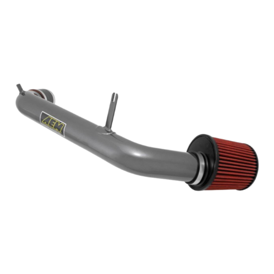
Dryflow Filter
Equipped with AEM
No Oil Required!
INSTALLATION INSTRUCTIONS
PART NUMBER: 21-718
SEE*NOTE
2012-13 HYUNDAI
ELANTRA
1.8L
*NOTE: Legal in California only for racing vehicles which may never be used upon a highway
AEM Induction Systems
1 (800) 992-3000
WWW: http://www.aemintakes.com
Advertisement

Related Manuals for AEM 21-718


Summary of Contents for AEM 21-718
- Page 1 Dryflow Filter Equipped with AEM No Oil Required! INSTALLATION INSTRUCTIONS PART NUMBER: 21-718 SEE*NOTE 2012-13 HYUNDAI ELANTRA 1.8L *NOTE: Legal in California only for racing vehicles which may never be used upon a highway AEM Induction Systems 1 (800) 992-3000...
-
Page 2: Parts List
PARTS LIST Description Qty. Part Number TUBE, INTAKE, 2012 HYUNDAI ELANTRA 1.8L 2-1496 MOUNT, INSULATED, M6 X 0.625 1228598 WASHER, FLAT, M6 X 1.0 DIA. 08160 NUT, HEX, FLANGED M6-1.0 444.460.04 HOSE, COUPLER, SILICONE 2.75” DIA X 3.0 5-275 1/2” BNDHOSE CLAMP, #48, 2.56”-3.50” DIA. 9444 AIR FILTER ELEMENT ASSY. - Page 3 The AEM intake system is a performance product that can be used safely during mild weather conditions. During harsh and inclement weather conditions, you must return your vehicle to stock OEM airbox and intake tract configuration.
- Page 4 E. Unfasten the airbox clamps and remove the F. Remove the stock air filter. Do not discard. stock airbox lid and intake tube. G. Remove the 3 M6 mounting bolts with a 10mm H. Depress the center buttons of the two plastic socket.
- Page 5 K. Unscrew and remove the 3 front plastic clips L. Inside the wheel well area, remove the 3 M6 retaining the drivers’ side fender liner. Pull the bolts retaining the intake silencer to the frame fender liner aside to expose the stock intake silenc- support.
- Page 6 D. Then insert the outlet end of the intake tube C. Carefully install your new AEM Cold Air Intake into the silicone hose at the throttle body. tube (A) by first inserting the inlet into the fender well access hole and aligning the bracket mount to the insulated M6 mounting stud as shown.
- Page 7 F. Re-connect the PCV hose at the valve cover. at the breather nipple using the stock clamp as shown. G. Inside the fender well, mount your new AEM® Dry- H. If you drive regularly in inclement weather, con- flow™ Air Filter (G) onto the intake tube inlet. Rotate sider installing an AEM®...
- Page 8 K. Re-install the driver’s side wheel and torque L. Re-install the stock engine cover. down the lug nuts to the factory specifications found in your Vehicle Owner’s Manual using a torque wrench. BEFORE: The stock intake system. AFTER: AEM 21-718 Cold Air Intake System. 3/20/2013 10-407...
- Page 9 The powder coating should only be cleaned with a mild soap and water solution. Proof of purchase of both the vehicle and AEM intake system is required for redemption of a warranty claim.
Need help?
Do you have a question about the 21-718 and is the answer not in the manual?
Questions and answers