Advertisement
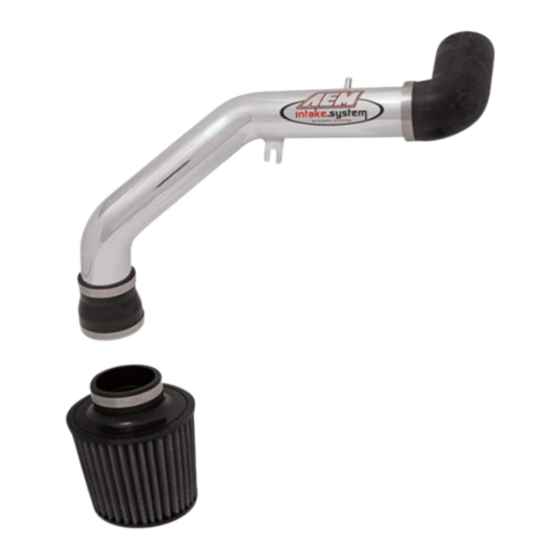
SHORT RAM
INTAKE
SYSTEM
Installation Instructions for:
Part Number 22-433
2000-2004 Mitsubishi Eclipse RS & GS
Manual Trans Only
ADVANCED ENGINE MANAGEMENT INC.
TH
2205 126
Street, Unit A Hawthorne, CA. 90250
Phone: (310) 484-2322 Fax: (310) 484-0152
www.aempower.com
Instruction Part Number: 10-7010
2000-2003 Mitsubishi Eclipse RS & GS 4G64 C.A.R.B. E.O. #D-392-21
2004 Mitsubishi Eclipse RS & GS 4G64 C.A.R.B. E.O. #D-392-28
© 2009 Advanced Engine Management, Inc.
Advertisement
Table of Contents

Related Manuals for AEM 22-433


Summary of Contents for AEM 22-433
- Page 1 SHORT RAM INTAKE SYSTEM Installation Instructions for: Part Number 22-433 2000-2004 Mitsubishi Eclipse RS & GS Manual Trans Only ADVANCED ENGINE MANAGEMENT INC. 2205 126 Street, Unit A Hawthorne, CA. 90250 Phone: (310) 484-2322 Fax: (310) 484-0152 www.aempower.com Instruction Part Number: 10-7010 2000-2003 Mitsubishi Eclipse RS &...
- Page 2 It is the most advanced short pipe air intake system on the market. Each system is specifical engineered for its particular application. All AEM Short Ram Air Intake Systems deliver maximum performance gains through lightweight, all-aluminum, mandrel-bent tubing that is tuned in both leng and diameter.
- Page 3 Read and understand these instructions BEFORE attempting to install this product. 1) Getting started a) Make sure vehic le is parked on a level surface. b) Set parking brake. c) Disconnect both b attery terminals. d) If engine has run within the past two ho urs let it cool down.
- Page 4 Loosen the three bolts that hold in the lower air box and remove it from the vehicle. 3) Installation of the AEM Short Ram Intake System When installing the Short Ram Intake System, DO NOT complet ely tighten the hose clamps or mounting tab hardware until instructed to do so later in these instructions.
- Page 5 c) Place rubber elbow with two hose clamps onto the d) Insert upper SRS pipe into rubber elbow. Attach rottle body. The long end attaches to the throttle body. support bracket to engine using the supplied bolt and washer. Place aluminum tab behind the plastic tab. e) Install the supplied breather hose as shown.
- Page 6 Support Chassis i) Proper installation of the rubber mount. j) AEM Short Ram System installed. 4) Reassemble the vehicle a) Inspect the engine bay for any loose too ls and check that all fasteners that were moved or removed are properly tightened, including the fender line b) Position the pipes so that they do not touch any other surfaces and tighten all hose clamps, nuts and bolts.
Need help?
Do you have a question about the 22-433 and is the answer not in the manual?
Questions and answers