Table of Contents

Related Manuals for thomann Stairville DDS-405 LC DMX 4 Ch. Dimmer


Summary of Contents for thomann Stairville DDS-405 LC DMX 4 Ch. Dimmer
- Page 1 DDS-405 LC DMX 4 Ch. Dimmer dimmer pack user manual...
- Page 2 Musikhaus Thomann Thomann GmbH Hans-Thomann-Straße 1 96138 Burgebrach Germany Telephone: +49 (0) 9546 9223-0 E-mail: info@thomann.de Internet: www.thomann.de 27.06.2018, ID: 428993...
-
Page 3: Table Of Contents
Table of contents Table of contents General notes............................... 4 1.1 Further information........................... 5 1.2 Notational conventions........................6 1.3 Symbols and signal words....................... 6 Safety instructions............................. 8 Features............................... 12 Installation and starting up........................ 13 Connections and controls........................15 Operating..............................20 Technical specifications........................26 Plug and connection assignment.................... -
Page 4: General Notes
General notes General notes This manual contains important instructions for the safe operation of the unit. Read and follow the safety instructions and all other instructions. Keep the manual for future reference. Make sure that it is available to all those using the device. If you sell the unit please make sure that the buyer also receives this manual. -
Page 5: Further Information
General notes 1.1 Further information On our website (www.thomann.de) you will find lots of further information and details on the following points: Download This manual is also available as PDF file for you to download. Use the search function in the electronic version to find the topics of Keyword search interest for you quickly. -
Page 6: Notational Conventions
General notes 1.2 Notational conventions This manual uses the following notational conventions: Letterings The letterings for connectors and controls are marked by square brackets and italics. Examples: [VOLUME] control, [Mono] button. Displays Texts and values displayed on the device are marked by quotation marks and italics. Examples: ‘24ch’... - Page 7 General notes Signal word Meaning DANGER! This combination of symbol and signal word indicates an immediate dangerous situation that will result in death or serious injury if it is not avoided. NOTICE! This combination of symbol and signal word indicates a pos- sible dangerous situation that can result in material and environmental damage if it is not avoided.
-
Page 8: Safety Instructions
Safety instructions Safety instructions Intended use This appliance is intended to be used to control the brightness of connected spotlights. Any other use or use under other operating conditions is considered to be improper and may result in personal injury or property damage. No liability will be assumed for damages resulting from improper use. - Page 9 Safety instructions DANGER! Electric shock caused by high voltages inside Within the device there are areas where high voltages may be present. Never remove any covers. There are no user-serviceable parts inside. Do not use the device if covers, protectors or optical components are missing or damaged.
- Page 10 Safety instructions NOTICE! Risk of fire Do not block areas of ventilation. Do not install the device near any direct heat source. Keep the device away from naked flames. NOTICE! Operating conditions This device has been designed for indoor use only. To prevent damage, never expose the device to any liquid or moisture.
- Page 11 Safety instructions NOTICE! Power supply Before connecting the device, ensure that the input voltage (AC outlet) matches the voltage rating of the device and that the AC outlet is protected by a residual current circuit breaker. Failure to do so could result in damage to the device and possibly injure the user.
-
Page 12: Features
Features Features 4 dimmer channels Outputs: 4 protective contact sockets Control via DMX 512 Individual DMX addressing per channel Channel function selectable per channel Operating modes: – – Automatic – Sound control Single channel protection dimmer pack... -
Page 13: Installation And Starting Up
Installation and starting up Installation and starting up Unpack and carefully check that there is no transportation damage before using the unit. Keep the equipment packaging. To fully protect the device against vibration, dust and moisture during transportation or storage use the original packaging or your own packaging material suitable for transport or storage, respectively. - Page 14 Installation and starting up Connections in DMX mode Connect the DMX input of the device to the DMX output of a DMX controller or another DMX device. Connect the output of the first DMX device to the input of the second one, and so on to form a daisy chain.
-
Page 15: Connections And Controls
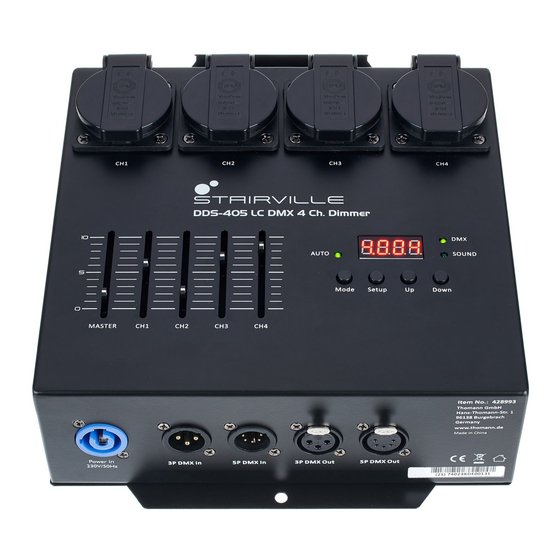
Connections and controls Connections and controls Front panel DDS-405 LC DMX 4 Ch. Dimmer... - Page 16 Connections and controls 1 [CH1]…[CH4] Dimmer outputs, 4 protective contact sockets. 2 [AUTO] Lights up when the unit is operating in ‘Automatic’ mode 3 Display 4 [DMX] Lights up when the unit is operating in ‘DMX’ mode. 5 [SOUND] Lights up when the unit is operating in ‘Sound control’ mode. 6 [Down] Decreases the displayed value by one and selects menu items 7 [Up]...
- Page 17 Connections and controls 8 [Setup] Chooses between the options of the selected mode 9 [Mode] Opens the menu and selects a menu item 10 [CH1]…[CH4] Sliders (faders) to set the brightness of each channel 11 [MASTER] Slider (fader) to set the overall brightness 12 Angles to attach the device to a wall or a crossbeam 13 Fuses for the channels 1…4 DDS-405 LC DMX 4 Ch.
- Page 18 Connections and controls Rear panel dimmer pack...
- Page 19 Connections and controls 14 [Power In] Lockable input socket (Power Twist) for the power supply of the connected spotlights and the device itself. 15 [DMX In] DMX input, 3 and 5-pin 16 [DMX Out] DMX output, 3 and 5-pin DDS-405 LC DMX 4 Ch. Dimmer...
-
Page 20: Operating
Operating Operating Starting the device To start up the device, connect it to the mains. The device is immediately ready for operation. Pull the power plug of the unit to turn it completely volt-free. dimmer pack... - Page 21 Operating Main menu Press [Mode] to activate the main menu. Use the buttons [Up] and [Down] to select a submenu. When the display shows the desired sub menu, press [Setup] to open it. To close the main menu, press [Mode]. The following table shows the setting options.
- Page 22 Operating Main menu Menu level 2 Menu level 3 Menu level 4 Meaning ‘-4--’ Output 4 on with full intensity ‘FS.00’ … ‘FS.99’ Strobe effect ‘Pr.02’ … ‘Pr.10’ Selecting a show ‘SP.01’ … ‘SP.FL’ Process speed ‘FS.00’ … ‘FS.99’ Strobe effect ‘CoLr’...
- Page 23 Operating Main menu Menu level 2 Menu level 3 Menu level 4 Meaning ‘1,001’ … ‘1,512’ Output 1 ‘2,001’ … ‘2,512’ Output 2 ‘3,001’ … ‘3,512’ Output 3 ‘4,001’ … ‘4,512’ Output 4 ‘SLAV’ Operating mode ‘Slave’ ‘Set’ Special functions ‘rSt’...
- Page 24 Operating Main menu Menu level 2 Menu level 3 Menu level 4 Meaning ‘dCu1’ , ‘dCu2’ , ‘dCu3’ , ‘dCu4’ Selecting dimmer or switch mode ‘O-di’ Dimmer mode ‘O-on’ Switch mode dimmer pack...
- Page 25 Operating Menu overview DDS-405 LC DMX 4 Ch. Dimmer...
-
Page 26: Technical Specifications
Technical specifications Technical specifications Voltage supply AC 100 – 240 V 50/60 Hz Electrical connection Power Twist, single-phase, 16 A Protection IP20 Channel fuse 5 mm × 20 mm, 8 A, 250 V, slow-blow (per channel) Signal input DMX 512 via 3- or 5-pin XLR socket Outputs 4 Schuko socket outlet, max. -
Page 27: Plug And Connection Assignment
Plug and connection assignment Plug and connection assignment Introduction This chapter will help you select the right cables and plugs to connect your valuable equip- ment so that a perfect light experience is guaranteed. Please take our tips, because especially in ‘Sound & Light’ caution is indicated: Even if a plug fits into a socket, the result of an incorrect connection may be a destroyed DMX controller, a short circuit or ‘just’... - Page 28 Plug and connection assignment DMX connections A five-pin XLR socket serves as DMX output, a five-pin XLR plug serves as DMX input. The drawing below and the table show the pin assignment of a matching coupling. Assignment Ground (shielding) Signal inverted (DMX–, ‘cold’) Signal (DMX+, ‘hot’) unused / second connection (DMX–) unused / second connection (DMX+)
-
Page 29: Protecting The Environment
Protecting the environment Protecting the environment Disposal of the packaging mate- rial For the transport and protective packaging, environmentally friendly materials have been chosen that can be supplied to normal recycling. Ensure that plastic bags, packaging, etc. are properly disposed of. Do not just dispose of these materials with your normal household waste, but make sure that they are collected for recycling. - Page 30 Notes dimmer pack...
- Page 32 Musikhaus Thomann · Hans-Thomann-Straße 1 · 96138 Burgebrach · Germany · www.thomann.de...
Need help?
Do you have a question about the Stairville DDS-405 LC DMX 4 Ch. Dimmer and is the answer not in the manual?
Questions and answers