Table of Contents
Advertisement
Quick Links
Advertisement
Table of Contents

Subscribe to Our Youtube Channel
Related Manuals for thomann STAIRVILLE D1210H


Summary of Contents for thomann STAIRVILLE D1210H
- Page 1 D1210H dimmerpack user manual...
- Page 2 Musikhaus Thomann Thomann GmbH Hans-Thomann-Straße 1 96138 Burgebrach Germany Telephone: +49 (0) 9546 9223-0 E-mail: info@thomann.de Internet: www.thomann.de 10.01.2017, ID: 153386 (V3)
-
Page 3: Table Of Contents
Table of contents Table of contents General information..........................4 1.1 Further information........................... 5 1.2 Notational conventions........................6 1.3 Symbols and signal words....................... 6 Safety instructions............................. 8 Features............................... 13 Installation and starting up........................ 14 Connections and operating elements................... 16 Operating..............................20 Technical specifications........................ -
Page 4: General Information
General information General information This manual contains important instructions for the safe operation of the unit. Read and follow the safety instructions and all other instructions. Keep the manual for future reference. Make sure that it is available to all those using the device. If you sell the unit please make sure that the buyer also receives this manual. -
Page 5: Further Information
General information 1.1 Further information On our website (www.thomann.de) you will find lots of further information and details on the following points: Download This manual is also available as PDF file for you to download. Use the search function in the electronic version to find the topics of Keyword search interest for you quickly. -
Page 6: Notational Conventions
General information 1.2 Notational conventions This manual uses the following notational conventions: Letterings The letterings for connectors and controls are marked by square brackets and italics. Examples: [VOLUME] control, [Mono] button. Displays Texts and values displayed on the device are marked by quotation marks and italics. Examples: ‘24ch’... - Page 7 General information Signal word Meaning DANGER! This combination of symbol and signal word indicates an immediate dangerous situation that will result in death or serious injury if it is not avoided. NOTICE! This combination of symbol and signal word indicates a pos‐ sible dangerous situation that can result in material and environmental damage if it is not avoided.
-
Page 8: Safety Instructions
Safety instructions Safety instructions Intended use This appliance is designed for professional use only and is intended to be used to control the brightness of connected spotlights. Use the device only as described in this user manual. Any other use or use under other operating conditions is considered to be improper and may result in personal injury or property damage. - Page 9 Safety instructions Safety DANGER! Danger for children Ensure that plastic bags, packaging, etc. are disposed of properly and are not within reach of babies and young children. Choking hazard! Ensure that children do not detach any small parts (e.g. knobs or the like) from the unit.
- Page 10 Safety instructions DANGER! Electric shock caused by short-circuit Do not modify the mains cable or the plug. Failure to do so could result in electric shock/death or fire. If in doubt, seek advice from a registered electrician. DANGER! Hazardous voltage Hazardous voltage may be present at cable ends and screw terminals.
- Page 11 Safety instructions NOTICE! Risk of fire Do not block areas of ventilation. Do not install the device near any direct heat source. Keep the device away from naked flames. NOTICE! Operating conditions This device has been designed for indoor use only. To prevent damage, never expose the device to any liquid or moisture.
- Page 12 Safety instructions NOTICE! Power supply Before connecting the device, ensure that the input voltage (AC outlet) matches the voltage rating of the device and that the AC outlet is protected by a residual current circuit breaker. Failure to do so could result in damage to the device and possibly injure the user.
-
Page 13: Features
Features Features General features 12 dimmer channels Outputs: 2 × Harting, 16 Pole Digital control system Control via DMX 512 Preheat, dimmer curve and maximum voltage can be adjusted individually Indicators for temperature and operation Test function Intelligent cooling control, large cooling ribs Single channel fuse (10 A) Voltage supply via CEE plug (32 A) Made in Europe... -
Page 14: Installation And Starting Up
Installation and starting up Installation and starting up Unpack and carefully check that there is no transportation damage before using the unit. Keep the equipment packaging. To fully protect the device against vibration, dust and moisture during transportation or storage use the original packaging or your own packaging material suitable for transport or storage, respectively. - Page 15 Installation and starting up Connections in ‘DMX’ mode Connect the DMX input of the device to the DMX output of a DMX controller or other DMX device. Connect the output of the first DMX device to the input of the second and so on, to form a series connection.
-
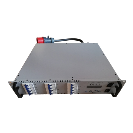
Page 16: Connections And Operating Elements
Connections and operating elements Connections and operating elements Front panel dimmerpack... - Page 17 Connections and operating elements 1 [Ch1]…[Ch12] Circuit breakers for channels 1…12, arranged in three blocks (L1…L3). With the circuit breakers, the desired channels are being activated ([I - ON]) or deactivated ([O - OFF]). 2 [L1]…[L3] Voltage indicators of blocks L1…L3. The LEDs of the connected blocks light red as soon as mains power is applied to the device.
- Page 18 Connections and operating elements 6 [Menu] Button to open the main menu and confirm display values. 7 Navigation buttons Buttons to navigate the device menu. dimmerpack...
- Page 19 Connections and operating elements Rear panel 8 Dimmer outputs, 2 × 16-pin Harting industrial connectors (note the device label when connecting the cables). 9 Fan. 10 Power cord with 5-pin CEE plug (32 A, 3 × 230 V). D1210H...
-
Page 20: Operating
Operating Operating Turning on and off Once you connect the device to the power supply, the LEDs of the connected blocks light red. Turn on the required channels via the associated circuit breakers (LEDs of active channels light up green). To switch off, disconnect the power plug from the 32-A-CEE outlet. - Page 21 Operating Menu overview D1210H...
- Page 22 Operating Setting the dimmer curve The device can be operated in dimmer mode (Linear, Sqrt, Exp1, Exp2) or in Switch mode ( ‘Off’ to DMX 64, ‘On’ from DMX 64). Proceed as follows to adjust the dimmer curve: Open the menu ‘Unit Setup’ , ‘Ch Curve’ (see menu overview). Confirm with the [Menu] button.
- Page 23 Operating Setting the maximum voltage The device offers the possibility to limit the maximum voltage for each channel, for example, to extend the life of the illuminants used. Proceed as follows to adjust the maximum voltage: Open the menu ‘Unit Setup’ , ‘Limit Ch 1=100’ (see menu overview). Confirm with the [Menu] button.
- Page 24 Operating Setting the preheat The preheat can be adjusted in a range from 0…50, where a value of 50 corresponds to approx. 20 %. In Switch mode ( ‘Off’ to DMX 64, ‘On’ from DMX 64), this function is not available. Proceed as follows to adjust the preheat: Open the menu ‘Unit Setup’...
- Page 25 Operating Setting the DMX address Proceed as follows to set the DMX address: Open the menu ‘Unit Setup’ , ‘DMX Addr Ch 1 =01’ (see menu overview). Confirm with the [Menu] button. ð The channel number display flashes. Select the desired channel with the navigation buttons or .
- Page 26 Operating When setting channel 1, the following channels are automatically addressed consec‐ utively. This addressing may be adjusted as described above. Switch-on mode The unit is operational as soon as power is applied. Activation is effected automatically. Proceed as follows to adjust the Switch-on mode: Open the menu ‘Unit Setup’...
- Page 27 Operating Test mode In Test mode, you can check the individual channels. Open the menu ‘Test Ch 1= 0’ (see menu overview). Confirm with the [Menu] button. ð The channel number display flashes. Select the desired channel with the navigation buttons or .
- Page 28 Operating Channel value display Proceed as follows to display the channel values: Open the menu ‘Unit Setup’ , ‘Channel 1= 68’ (see menu overview). Confirm with the [Menu] button. ð The channel number display flashes. Select the desired channel with the navigation buttons or .
- Page 29 Operating Checking DMX status To retrieve the DMX status, open the menu ‘Unit Status’ , ‘DMX Signal’ (see menu overview). When the signal is received correctly, the display will show ‘DMX Signal OK’ . On a faulty signal, ‘No DMX Signal’ appears. In this case, check the connecting cables and DMX settings on the device.
-
Page 30: Technical Specifications
Technical specifications Technical specifications Operating supply voltage 380 V 50 Hz Electrical connection Three-phase connection, max. 32 A per phase Channel fuse 1 × circuit breaker per channel, 10 A, ‘C’ characteristic Signal input DMX 512 via 3-pin XLR socket Outputs 2 ×... -
Page 31: Plug And Connection Assignment
Plug and connection assignment Plug and connection assignment Introduction This chapter will help you select the right cables and plugs to connect your valuable equip‐ ment so that a perfect light experience is guaranteed. Please take our tips, because especially in ‘Sound & Light’ caution is indicated: Even if a plug fits into a socket, the result of an incorrect connection may be a destroyed DMX controller, a short circuit or ‘just’... -
Page 32: Protecting The Environment
Protecting the environment Protecting the environment Disposal of the packaging mate‐ rial For the transport and protective packaging, environmentally friendly materials have been chosen that can be supplied to normal recycling. Ensure that plastic bags, packaging, etc. are properly disposed of. Do not just dispose of these materials with your normal household waste, but make sure that they are collected for recycling. - Page 33 Notes D1210H...
- Page 34 Notes dimmerpack...
- Page 36 Musikhaus Thomann · Hans-Thomann-Straße 1 · 96138 Burgebrach · Germany · www.thomann.de...
Need help?
Do you have a question about the STAIRVILLE D1210H and is the answer not in the manual?
Questions and answers