Table of Contents
Advertisement
Advertisement
Table of Contents

Related Manuals for IAME ReedJet AUS 100cc-TaG


Summary of Contents for IAME ReedJet AUS 100cc-TaG
- Page 1 REEDJET AUS 100cc – TaG Text INSTALLATION MANUAL MAN-033 01/11/04...
-
Page 2: General Description Of Engine
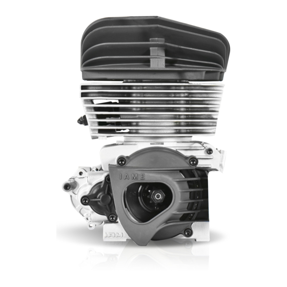
GENERAL DESCRIPTION OF ENGINE This engine of the "TaG" series (Touch and Go) has been expressly designed and developed to power Karts for hobby racing on closed tracks, destined for this specific purpose. When designing this new line of engines, the technical solutions already adopted for the high performance engines were applied, in order to guarantee the highest reliability of components, when the operating limits are respected. - Page 3 12V/0.30 kW Clutch: Automatic, dry centrifugal ATTENTION: Never exceed the above limits, no obligation of IAME S.p.A. exists in case the above limits are exceeded. Operational RPM limits (the motor not included RPM Limiter): Max.RPM / 1’ : 15.000 RPM...
- Page 4 ACCESSORIES EXHAUST GROUP BATTERY SUPPORT KIT CLUTCH COVER + H.T. COIL PUSH BUTTONS BRACKET COPERCHIO FRIZIONE WIRING HARNESS INLET SILENCER + FILTER SPARKPLUG KIT TILLOTSON CARBURETTOR MAN-072...
-
Page 5: Engine Identification Number
NOTE: In case of need for spares and when contacting the IAME Support Centers, please always refer to the Engine Serial Number and to the engine model. MAN-072... -
Page 6: Preparation And Installation Of The Engine On The Chassis
2- PREPARATION AND INSTALLATION OF THE ENGINE ON THE CHASSIS NOTE: In case the engine is supplied already assembled on the chassis, it is at care of the assembler to follow these instructions. The final customer, in this case, can skip this section and can start reading from section 4. - Page 7 2.2- EXHAUST MANIFOLD INSTALLATION NOTE: THE ENGINE IS SUPPLIED WITH AN EXHAUST CARD BOARD COVER TO PROTECT THE INTERNAL PARTS. THE EXHAUST GASKET AND STUD BOLTS ARE ALREADY MOUNTED. REMOVE THE NUTS AND THE EXHAUST CARD BOARD COVER MAKE SURE THAT THE EXHAUST GASKET IS IN Fig.1 SEAT AND INSTALL THE EXHAUST MANIFOLD.
- Page 8 2.3- INSTALLATION CARBURETTOR 12 POINT WRENCH 10mm INSTALL THE GAS CABLE CLAMP ON THE Fig.5 SUPPORT (SEE FIG. 5) SCREWDRIVER 4.8 mm / Torx T20 REMOVE THE 2 3.5mm SCREWS ON THE CARB. Fig.6 PUMP (IN CORRESPONDENCE OF THE THROTTLE LEVER). (SEE FIG.
- Page 9 FINAL STEP - AFTER THE COMPLETE INSTALLATION OF THE ENGINE ON THE CHASSIS. CONNECT THE FUEL FEED HOSE TO THE INLET FITTING ON THE CARBURETTOR CAP. (SEE FIG. 10) Fig.10 2.4- PREPARATION AND INSTALLATON OF THE ENGINE-MOUNT NOTE: ALL THE DIMENSIONS IN MILLIMETERS DRILL 4 HOLES (DIAM.
- Page 10 INSTALL ENGINE CHASSIS POSITION THE ENGINE ON THE 2 OUTSIDE MAIN RAILS AND FIX THE MOTOR-MOUNT WITH THE TWO CLAMPS. (SEE FIG.11) SUGGESTION: NEVER TORQUE COMPLETELY THE CLAMPS UNTIL THE CHAIN IS INSTALLED AND PROPERLY ALIGNED. Fig.11 CHECK THE ALIGNMENT OF THE ENGINE SPROCKET AND THE AXLE SPROCKET WITH A STRAIGHT EDGE.
- Page 11 INSTALL THE CLUTCH COVER WITH ALLEN WRENCH 5 mm H.T. COIL Fig.15 REMOVED THE 3 SCREWS TCEI M6x30 FROM THE CRANKCASE (SEE FIG. 15) AND INSTALL THE CLUTCH COVER WITH THE H.T. COIL. (SEE FIG.16) TIGHTEN THE 3 SCREW AT 8÷10 Nm ATTENTION: ALWAYS MAKE SURE THAT THE GROUND CABLE ALWAYS CONNECTS THE COIL WITH THE...
-
Page 12: Electrical Connections
2.7- ELECTRICAL CONNECTIONS (refer to the attached electrical scheme) NOTE: FOR A CORRECT INSTALLATION FOLLOW THE UNDER SHOWN INSTRUCTIONS. INSERT BATTERY FIXING STRIPE IN THE DEDICATED SLOTS. (SEE FIG. 17) Fig.17 PLACE THE BATTERY SUPPORT CLAMPS ON THE CHASSIS TUBE, FIX THEM THROUGH THE SPECIFIC SCREWS ON THE SUPPORT PIPES (SCREW TE M6x25 –... - Page 13 PLACE THE STARTER BUTTON IN THE PROPER HOUSING THROUGH PROVIDED NUT. (SEE FIG.21) FIX AND PLACE THE BUTTON WITH THE FASTON ORIENTED AS IN THE FIGURE: Fig.21 Fig.22 PASS CABLE WITH BUTTONS TERMINALS IN THE BRACKET, CONNECT THE 2 FASTONS TO THE STARTER BUTTON AND TIGHTEN THE STOP RED BUTTON WITH THE PROVIDED NUT (SEE FIG.
- Page 14 Fig.26 FIX THE KIT CABLES THROUGH A STRAP ACCORDING TO THE CHASSIS AND THE NEED. (SEE FIG.26) Fig.27 CONNECT THE SUPERSEAL 4 WAYS MALE FASTON CONNECTOR TO THE FEMALE CONNECTOR OF THE STOP CABLE. (SEE FIG.27) Fig.28 CONNECT THE MALE FASTON OF THE STOP CABLE FEMALE FASTON...
- Page 15 ASSEMBLY OF THE Fig.32 INTAKE SILENCER MAKE SURE THAT THE INTAKE SILENCER IS POSITIONED WITH THE HOLES UPSIDE AND THAT THEY ARE NOT OBSTRUCTED. TIGHTEN CLAMP INLET SILENCER SUPPORT ON THE CARBURETTOR AND FIX THE INLET SILENCER WITH THE DEDICATED CLAMP ON THE CHASSIS TUBE. (SEE FIG.
- Page 16 3.1- MIXTURE OIL AND FUEL Use unleaded Premium gasoline 95 RON, mixed with oil at 5% (20:1). Use oils containing castor’s oil that guarantees an optimized lubrication at high temperature. As on the other hand, castor oils create gummy residues that give origin to carbon deposits causing incrustations, it is necessary to check and clean the piston and the head at least every 5 ÷10 hours.
-
Page 17: Carburettor Setting
3.2- CARBURETTOR SETTING SCREW ( I ) OF MINIMUM SCREW ( H ) HIGH SPEED MIXTURE SETTING MMMIXTURESCREW SCREW ( L ) LOW SPEED MIXTURE 1 T.O. RICH LEAN ¼ ¾ T.O. T.O. ½ T.O. T.O. = TURNS OPEN Generally the correct settng of the carburettor screws is the following : L (close the screw completely and then open): 2 and 05' T.O. -
Page 18: Starting And Stopping The Engine
3.3- STARTING AND STOPPING THE ENGINE The engine start is achieved by pushing the black rubber button on the bracket. If the engine does not start, stop and try again. If the engine does not start within 5 seconds (check that gasoline flows to the carburettor), stop the procedure and try after about 15 seconds. -
Page 19: Exhaust Gas Temperature Probe
3.7- EXHAUST GAS TEMPERATURE PROBE The exhaust muffler is not provided with a temperature probe lodgment. If necessary, it is possible to install the probe support and as indicated in the figure. Whenever you wish to employ the probe, please proceed as shown in the figure below. drill exhaust Ø4.2 for cylindrical probe drill exhaust Ø4.2 and thread M5 for threaded probe 3.8-... - Page 20 3.9- INSTRUCTIONS FOR THE DISASSEMBLY / ASSEMBLY OF THE CLUTCH GROUP WARNING : The following operations can be made by a skilled mechanic, with the proper tools shown in the text ; otherwise, it is necessaty to apply to an Authorized Service Center. Refer to the following drawing during the different operations.
- Page 21 Before assembling the clutch, wash with the diluent : the shaft cone, the starter wheel and the clutch drum. Clutch assembly 1. Asseble the starter wheel on the clutch hub by Allen wrench 5mm – T type (torque at 10÷12 matching the 3 holes and the dragging pin 2.
-
Page 22: Spark Plug And Thermal Degree
Never let the battery tension drop under 8V as under this limit the battery can not be used and it will have to be replaced. Never put the battery in contact with solvents, oils, plastifiers or rags containing such elements as the battery external case could be damaged. Never press and/or bend or overheat the battery terminals (for ex. - Page 23 The operating limit for the Reedjet 100cc AUS engine is 15.000 RPM. ATTENTION: Never exceed the above limit. No obligation of IAME exists in case the above limit is exceed. In case the user wishes to optimize the sprocket ratio on the track, in order to achieve the best possible performance and without overloading the engine, follow the under shown recommendations.
-
Page 24: Replacement Of The Starter Brushes
3.13- REPLACEMENT OF THE STARTER BRUSHES OPERATIONS PICTURES Fig.1 DISASSEMBLE THE STARTER MOTOR - LOOSE THE SCREW M6X30 ON THE ADDITIONAL STARTER SUPPORT (See Fig.1). (5mm ALLEN WRENCH T TYPE) - REMOVE THE ADDITIONAL STARTER SUPPORT Fig.2 3 SCREWS M6X25 (See Fig.2). (5mm ALLEN WRENCH T TYPE) - REMOVE THE STARTER SUPPORT Fig.3... - Page 25 OPENING THE STARTER MOTOR Fig.6 Fig.1 - UNSCREW THE M4 SCREW FIXING THE INPUT CABLE (See Fig.6) (SCREWDRIVER) Fig.7 - UNSCREW THE 3 M5 “C” SCREWS (See Fig.7) (SCREWDRIVER) MAN-072...
- Page 26 - REMOVE THE DRUM FROM THE STARTER Fig.4 MOTOR KEEPING THE ROTOR IN ITS SEAT (BE SURE TO HOLD THE ROTOR ON ITS TOOTHED SIDE TO PREVENT THE BRUSHES FROM FALLING OUT FROM THEIR SEAT (see Fig . 8) Fig.8 Fig.9 - EXTRACT THE ROTOR FROM THE STARTER MOTOR HEAD (see Fig.
- Page 27 - REMOVE THE SILICON FROM BRUSHES WITH A SCREWDRIVER (see Fig. 11) - REMOVE SPRINGS Fig.12 - REMOVE THE BRUSH MAKING PRESSURE ON Fig.9 THE TIN PLATE TERMINAL EXTERNALLY (see Fig. 13) Fig.13 - INSTALL NEW BRUSH TERMINAL (See Fig.14). - PLACE THE LITTLE RUBBER CAP ON THE TERMINAL.
- Page 28 Fig.16 REPLACEMENT OF THE BRUSH “B” - LOOSE THE SCREW M3 “G” (See Fig.16) - EXTRACT THE BRUSH - FIX THE NEW BRUSH WITH SCREW M6 (SCREWDRIVER) CLOSING THE STARTER - INSERT THE NEW BRUSH SPRING "A" INTO ITS SEAT. - INSTALL THE BRUSH.
- Page 29 - CHECK THAT THE O-RING "H" IS INSTALLED ON THE STARTER HEAD. - INSERT THE STARTER DRUM ON THE HEAD BEING CAREFUL TO PREVENT THE ROTOR FROM ROTATING AND TO PREVENT THE BRUSHES FROM FALLING OUT OF THEIR SEAT (see Fig. 20). Fig.20 - TORQUE THE 3 SCREWS M5 (see Fig.21).
-
Page 30: Schedule Maintenance
3.14- SCHEDULE MAINTENANCE Following some simple maintenance standards will allow the engine to perform more reliably and have a longer life. SCHEDULE COMPONENTS ACTIONS AND COMMENTS Before each use Flexible spring Check status Muffler Check status and fixing (springs) Engine sprocket Check wear Check alignment... -
Page 31: Troubleshooting
3.15- TROUBLESHOOTING Here below there are some of the most common problems, the possible causes and the recommended solutions to solve them. PROBLEMS PROBABLE CAUSES SOLUTIONS Starter will not crank when pushing Bad connections on starter cables Check connections and tighten the start button Bad grounding Check connections and tighten... -
Page 32: Engine And Accessories Preservation
3.19- ENGINE AND ACCESSORIES PRESERVATION When the engine is not operating for a long period, it must be preserved in the most suitable way: Disconnect the battery and recharge it regularly (see sect. 12) Disassemble the carburettor and clean it Seal the inlet and the exhaust with adhesive paper External parts must be cleaned and steel parts, subject to oxidation, protected with light film oil.
Need help?
Do you have a question about the ReedJet AUS 100cc-TaG and is the answer not in the manual?
Questions and answers