Table of Contents
Advertisement
Quick Links
Download this manual
See also:
Operating Manual
Advertisement
Table of Contents

Subscribe to Our Youtube Channel
Related Manuals for Stryker Zoom 2040


Summary of Contents for Stryker Zoom 2040
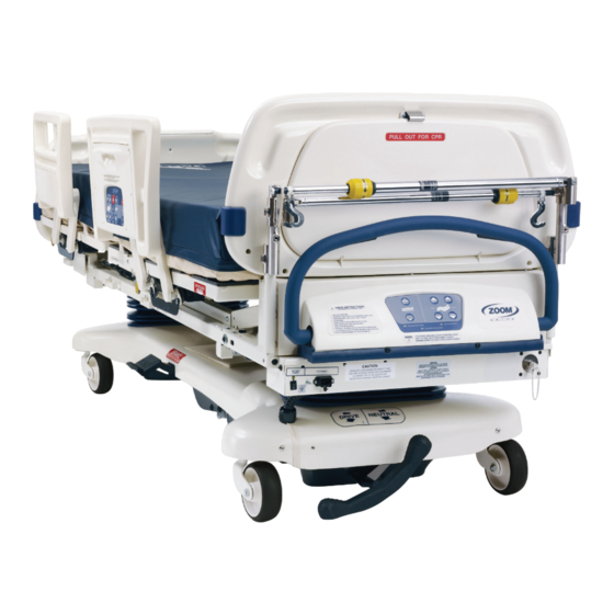
- Page 1 ZOOM ® Critical Care Bed Model 2040 Maintenance Manual For Parts or Technical Assistance: USA: 1-800-327-0770 (option 2) Canada: 1-888-233-6888 2010/04 2040-309-002 REV B www.stryker.com...
-
Page 3: Table Of Contents
Lift Motor Coupler Replacement ............57 www.stryker.com... - Page 4 Head End Bottom Cover..............113 2040-309-002 REV B www.stryker.com...
- Page 5 Optional Foot Board Scale Module Assembly ..........199 www.stryker.com...
- Page 6 International Warranty Clause............220 2040-309-002 REV B www.stryker.com...
-
Page 7: Introduction
Introduction Intended Use This manual is designed to assist you with the maintenance of Stryker Model 2040 Zoom ® Critical Care Bed. Carefully read this manual thoroughly before using the equipment or beginning maintenance on it. To ensure safe operation of this equipment, it is recommended that methods and procedures be established for educating and training staff on the safe operation of this bed. -
Page 8: Warning / Caution / Note Definition
Note This provides special information to make maintenance easier or important instructions clearer. Return To Table of Contents 2040-309-002 REV B www.stryker.com... -
Page 9: Symbols
(WEEE), this symbol indicates that the product must not be disposed of as unsorted municipal waste, but should be collected separately. Refer to your local distributor for return and/or collection systems available in your country. Return To Table of Contents www.stryker.com 2040-309-002 REV B... -
Page 10: Summary Of Safety Precautions
When using any mattress and/or mattress overlay that increases the overall height greater than 6” extra caution and/or operator supervision is required to help reduce the likelihood of a patient fall occurring. Return To Table of Contents 2040-309-002 REV B www.stryker.com... - Page 11 The battery tray assembly weighs 50 pounds. Take care when removing the two hexagonal head screws securing it to the base frame or personal injury could result. • The 2040 Patient Transport Frame is not intended for pediatric use or for patients under 50 pounds. Return To Table of Contents www.stryker.com 2040-309-002 REV B...
- Page 12 Grounding continuity should be checked periodically. • Do not use for life-sustaining equipment. • Use only hospital-grade equipment with electrical outlet. • Unplug free-standing equipment before transporting the bed. WARNING Potential pinch points. Return To Table of Contents 2040-309-002 REV B www.stryker.com...
-
Page 13: Ibed Awareness Option
Awareness as the display information to troubleshoot the bed will get lost. • If the optional iBED Awareness system is being used; use of accessories that cover the alert light are not recommended. Return To Table of Contents www.stryker.com 2040-309-002 REV B... -
Page 14: Setup Procedures
Run through the operation of the drive wheel to ensure it is operating properly. • If the bed is equipped with the Nurse Call option, verify it is functioning properly prior to patient use. Return To Table of Contents 2040-309-002 REV B www.stryker.com... -
Page 15: Optional Ibed Awareness Maintenance Menu Guide
Press the “Enter/Check” button when the display shows the proper weight. The display should present the following message: “Place Weight in Center”. Place the weight in the center of the bed. Return To Table of Contents www.stryker.com 2040-309-002 REV B... - Page 16 “Do Not Touch Bed”. The message should be flashing. 34. The display should present the following message when the bed is ready to continue: “Press Reverse Trend”. 35. Press the reverse trend button. Return To Table of Contents 2040-309-002 REV B www.stryker.com...
- Page 17 The TV Configuration screen should reappear after 2 seconds and the new setting should be highlighted. Pressing the Exit/X button or if the screen remains dormant for more than 30 seconds, the display will return you to the Maintenance Menu screen, without saving any changes. Return To Table of Contents www.stryker.com 2040-309-002 REV B...
- Page 18 When the menu item is selected the maximum values for each of the load cells will be displayed. • Values should update every 0.25 seconds. Note: The scale information and statistics are important when trying to diagnose the scale system. Return To Table of Contents 2040-309-002 REV B www.stryker.com...
- Page 19 The Maintenance Menu screen should reappear after 2 seconds and the new setting should be highlighted. Note: Items that are cleared during this operation are: • Maximums (for each load cell) • Minimums (for each load cell) Return To Table of Contents www.stryker.com 2040-309-002 REV B...
- Page 20 If “Exit” is chosen, then you will be returned to the Maintenance Menu screen. If “Enter’ is chosen, then the error log is cleared and a message is displayed: “Error Log Cleared” and you will be returned to the Maintenance Menu screen. Return To Table of Contents 2040-309-002 REV B www.stryker.com...
- Page 21 Exit Maintenance • This feature allows the operator to exit the menu back to the previous screen. • When this menu item is selected the screen will exit to the “Status” screen. Return To Table of Contents www.stryker.com 2040-309-002 REV B...
-
Page 22: Preventative Maintenance
Battery Charger Circuit Breaker If the battery charger circuit breaker(s) located under the litter on the patient’s head end, left side are tripped, refer to the troubleshooting section of the maintenance manual. Return To Table of Contents 2040-309-002 REV B www.stryker.com... -
Page 23: Checklist
_____ iBED Awareness Side Indicator LEDs working properly (iBED Awareness option) _____ Inspect footboard control labeling for signs of degradation. (iBED Awareness option) _____ Fowler functioning properly Bed Serial Number: Completed by: _______________________________________ Date: _________________ Return To Table of Contents www.stryker.com 2040-309-002 REV B... -
Page 24: Cleaning
SOME CLEANING PRODUCTS ARE CORROSIVE IN NATURE AND MAY CAUSE DAMAGE TO THE PRODUCT IF USED IMPROPERLY. If the products suggested above are used to clean Stryker patient care equipment, measures must be taken to insure the bed is wiped with a damp cloth soaked in clean water and thoroughly dried following cleaning. -
Page 25: Troubleshooting Guide
CPU board. E. Check for 120 VAC at connector O on the CPU board. a. If voltage is present, replace the CPU board. F. Verify bed function and return to service. Return To Table of Contents www.stryker.com 2040-309-002 REV B... - Page 26 2. If motors are not running, check voltage at motor connection. 3. If voltage is present at motor, check capacitors or motors. D. Verify bed function and return to service. Return To Table of Contents 2040-309-002 REV B www.stryker.com...
- Page 27 If voltage is not present, replace the CPU board. b. If 120 VAC is present, check the capacitor and motor. C. Refer to Fowler Mechanism Customer Guide (2030-009-028). D. Verify bed function and return to service. Return To Table of Contents www.stryker.com 2040-309-002 REV B...
- Page 28 Three LED’s flash = 66% - 100% charged. Two LED’s flash = 33% - 66% charged. One LED flashes = Less than 33% charged. No LED’s flash = No significant charge remaining. Return To Table of Contents 2040-309-002 REV B www.stryker.com...
- Page 29 (Refer to NA 0000-059-179 Item) does not charge. Circuit Breaker 2. B. Check the battery charger. C. Check all cable connections on the charger. Return To Table of Contents www.stryker.com 2040-309-002 REV B...
- Page 30 Power supply board: Battery wire Are all the Non−Zoom Is the Zoom functions working ? Replace Inverter/ working properly? connectors Charger assembly reversal Replace Inverter/ Charger Inverter is Good Zoom is Good assembly Return To Table of Contents 2040-309-002 REV B www.stryker.com...
- Page 31 Is Battery Volage Sufficient? Replace the Batteries (> 21VDC) Plug Bed into Wall Socket (For Charging/Test) Replace the Inverter Is the Battery Voltage / Charger assembly Increasing? Return Bed to Service Return To Table of Contents www.stryker.com 2040-309-002 REV B...
-
Page 32: Ibed Awareness System Error Codes
Zero Fail error occurs when the system can- Logged Scale, Bed Exit, iBED Awareness not provide a stable zero value for three con- secutive attempts at zeroing the product. Return To Table of Contents Return To Table of Contents 2040-309-002 REV B www.stryker.com... -
Page 33: Error Messages
The message “Scale Calib. Err” will be displayed in the lower status screen window. Return To Table of Contents Return To Table of Contents www.stryker.com 2040-309-002 REV B... - Page 34 This will cause the product to stop all function and product a message screen indicating the error number and the message “Unknown Bed Type - Call Service” Return To Table of Contents 2040-309-002 REV B www.stryker.com...
- Page 35 CalibrationException If the scale calibration routine fails then the Message Motion message “Calibration Error” will be displayed for 4 seconds and then return to the mainte- nance menu. Return To Table of Contents www.stryker.com 2040-309-002 REV B...
-
Page 36: Quick Reference Replacement Parts List
The parts and accessories listed on this page are all currently available for purchase. Some of the parts identified on the assembly drawing parts in this manual may not be individually available for purchase. Please call Stryker Customer Service USA: 1-800-327-0770 (Option 2), Canada: 1-888-233-6888 for availability and pricing. - Page 37 Foot End Siderail Switch, Left 2032-030-025 Head End Siderail Switch, Right 2032-030-020 Head End Siderail Switch, Left 2032-030-015 LBS Light Indicator, Right 3004-300-225 LBS Light Indicator, Left 3004-300-230 CPU Board 3003-407-900 Return To Table of Contents www.stryker.com 2040-309-002 REV B...
- Page 38 Notes Return To Table of Contents 2040-309-002 REV B www.stryker.com...
-
Page 39: Electrical System Information
Electrical System Information Standard CPU Board = 3002-407-950 / iBED Awareness CPU Board - 3003-407-900 CPU BOARD − 3002−407−950 Return To Table of Contents www.stryker.com 2040-309-002 REV B... - Page 40 Fowler Pot Wiper 9 VDC Pin 2 (Red) Pin 1 (Black) Nurse Call Backup Battery 12 VDC when Bed Pin 1 (Red) Pin 2 (Black) Bed Exit Beeper Exit is Alarming Return To Table of Contents 2040-309-002 REV B www.stryker.com...
-
Page 41: Software Configuration
Electrical System Information Software Configuration Return To Table of Contents www.stryker.com 2040-309-002 REV B... - Page 42 To verify the switch settings, check what the foot board LCD displays in the burn-in mode. For beds with a scale system, select software config. in the diagnostic mode. Functional Test ICU-ZOOM/Standard Bed ICU-ZOOM/Scale//Bed Exit ICU-ZOOM/Scale/Zone Control/Bed Exit ICU-Scale/Bed Exit/Bed Status (iBED Awareness Option) ICE-ZOOM/Scale/Bed Exit/Bed Status (iBED Awareness Option) Return To Table of Contents 2040-309-002 REV B www.stryker.com...
-
Page 43: Power Supply - 0000-059-157
Pin 2 Pin 4 or 5 Pin 3 Pin 4 or 5 Pin 4 Pin 4 or 5 Pin 5 Pin 4 or 5 -12V Pin 6 Pin 4 or 5 Return To Table of Contents www.stryker.com 2040-309-002 REV B... -
Page 44: Inverter - Charger Board - 3002-001-030
Unplugged Pin 3 Blue HDR 2 110V Pin 2 Brown Pin 1 Blue From Wall - plugged in HDR 3 120V Pin 2 Plug-In Pin 1 Wall Voltage - plugged in Return To Table of Contents 2040-309-002 REV B www.stryker.com... -
Page 45: Display/Cpu - 2040-031-910
DC Voltage to Pot HDR 7 Continuity Pin 1 Pin 4 Right Hand Switch HDR 3 Continuity Pin 1 Pin 4 Left Hand Switch HDR 2 26 VDC Pin 3 Pin 1 Battery Voltage Return To Table of Contents www.stryker.com 2040-309-002 REV B... -
Page 46: Ac Crossover Board - 2040-031-900
120 VAC Pin 2 Pin 1 AC Output of Board to Main Power +5 VDC when AC is Unplugged from the HDR 4 (E) +5 VDC Pin 4 Pin 1 Wall Receptacle Return To Table of Contents 2040-309-002 REV B www.stryker.com... -
Page 47: Dc Motor Power Board - 2040-001-900
5 VDC Disengaged HDR 2 (Q) Pin 1 Red Pin 3 Black Drive Wheel 0 VDC Engaged 5 VDC Disengaged HDR 2 (Q) Pin 2 Red Pin 3 Black Brakes 0 VDC Engaged Return To Table of Contents www.stryker.com 2040-309-002 REV B... -
Page 48: Inverter Protection Features
The inverter generates 115 VAC, the same as a wall receptacle. To prevent injury, do not put anything into the electrical outlets other than an appliance power cord. Keep the outlets covered when not in use. Do not submerge the unit or subject into moisture. Return To Table of Contents 2040-309-002 REV B www.stryker.com... - Page 49 Electrical System Information 37−PIN CONNECTOR STRYKER PENDANT PORT Pin 1 Option 2 Common Pin 2 Read Light Pin 3 Room Light Pin 4 Speaker High Pin 5 Pot Wiper Pin 6 Radio Common Pin 7 Nurse Call Interlock Pin 8 Audio Transfer -...
- Page 50 Part No. Part Name Qty. Item Part No. Part Name Qty. 3002-045-805 BCT Unit − − 3001-303-825 37-Pin Cable 3001−303−825 37−Pin Cable 3002-045-806 Instructions 3002−45−806 Instructions 3000-303-871 9V Battery 3000−303−871 9V Battery Return To Table of Contents 2040-309-002 REV B www.stryker.com...
-
Page 51: Service Information
2 and 3 of the following procedure. Do not place unprotected circuit boards on the floor. All circuit boards to be returned to Stryker Medical should be shipped in the static shielding bags the new boards were shipped in. -
Page 52: Brake Pedal Replacement
Push the brake rod through the frame until the brake pedal is clear. Remove the brake pedal. Reverse steps 1 - 6 to attach the new brake pedal. Note Use Loctite 242 when reinstalling the bolts and torque the bolts to 25 foot-pounds. Return To Table of Contents 2040-309-002 REV B www.stryker.com... -
Page 53: Lift Motor And Capacitor Removal And Replacement
The drive shaft on the new motor might need to be turned with a 7/16” open end wrench to align with the coupler. The procedure for lift motor and capacitor removal and replacement is the same for both ends of the bed. Return To Table of Contents www.stryker.com 2040-309-002 REV B... -
Page 54: Lift Housing Removal And Replacement
11. Reverse steps 1 - 10 to reinstall the lift housing assembly after service is completed. Note The procedure for lift housing removal and replacement is the same for both ends of the bed. Return To Table of Contents 2040-309-002 REV B www.stryker.com... -
Page 55: Lift Potentiometer Replacement And Adjustment
11. Reverse steps 4 - 9 to install the new potentiometer and potentiometer housing assembly. 12. After installing the new potentiometer, the “burn-in” procedure below must be followed. Note Be sure to maintain the pot position while installing. Return To Table of Contents www.stryker.com 2040-309-002 REV B... -
Page 56: Lift Potentiometer "Burn-In" (Standard Bed)
Up/Down Lock button until the light flashes. CAUTION For both procedures above, do not run the litter all the way down while in the diagnostics mode. Damage to the bottom lift covers could result. Return To Table of Contents 2040-309-002 REV B www.stryker.com... -
Page 57: Lift Motor Coupler Replacement
(C). The motor coupler can now be removed from the lift housing. Reverse steps 1 - 4 to install the new motor coupler and bushings. Return To Table of Contents www.stryker.com 2040-309-002 REV B... -
Page 58: Power And Sensor Coil Cord Replacement
Arrange the cords exactly as shown in the illustration (left in front of right). If this is not done correctly, damage to the cords will result. Return To Table of Contents 2040-309-002 REV B www.stryker.com... -
Page 59: Www.stryker.com 2040-309-002 Rev B
Service information VIEW FROM CENTER OF BED Return To Table of Contents www.stryker.com 2040-309-002 REV B... -
Page 60: Battery Removal And Replacement
12. Reverse steps 1 - 11 to install the new batteries. Complete the last four items of the setup procedures section. Return To Table of Contents 2040-309-002 REV B www.stryker.com... -
Page 61: Dc Motor Board Removal And Replacement
Remove all cables from the motor board and remove the board. Note Note the locations of the cables so you can connect them properly to the new motor board. 10. Reverse steps 1 - 8 to install the new motor board. Return To Table of Contents www.stryker.com 2040-309-002 REV B... -
Page 62: Drive Motor Removal And Replacement
Reverse steps 1 - 8 to install the new drive motor. 10. Run through the operation of the power drive wheel to ensure it is operating properly before returning the unit to service. Return To Table of Contents 2040-309-002 REV B www.stryker.com... -
Page 63: Drive Wheel Removal And Replacement
Using a 1/2” socket wrench, remove the bolt holding the wheel to the drive motor. Slide the wheel off the motor shaft. Reverse steps 1 - 3 to install the new drive wheel and reinstall the drive motor. Return To Table of Contents www.stryker.com 2040-309-002 REV B... -
Page 64: Load Cell Replacement
Using a saw horse or the equivalent, support the litter at the end where the load cell was removed. Reverse the above procedure to install the new load cell. Note The scale calibration procedure must be performed after the load cell is replaced (Refer to Scale System Diagnostics and Calibration section). Return To Table of Contents 2040-309-002 REV B www.stryker.com... -
Page 65: Scale System Diagnostics And Calibration
LCD displays “Select Corner”, press one of these buttons to cycle through the corners and to select the load cell assembly at the desired corner. A. Zero = Cycle up through the four corners. B. Scale On/Off = Cycle down through the four corners. Return To Table of Contents www.stryker.com 2040-309-002 REV B... - Page 66 11. Level the bed at a full up or full down position. Remove the weight and zero the bed. 12. Verify scale accuracy and functionality before returning the bed to service. Return To Table of Contents 2040-309-002 REV B www.stryker.com...
-
Page 67: Head Motor Removal And Replacement
Remove the motor mounting bracket from the old motor and install it on the replacement motor. Reverse steps 3 through 6 to install the replacement motor. Verify the unit is working properly before returning it to service. Return To Table of Contents www.stryker.com 2040-309-002 REV B... -
Page 68: Knee Motor Removal And Replacement
12. Pull the foot panel toward the foot end of the bed. This causes the knee motor linkage to roll back past center. CAUTION If step 12 is not done, damage to the motor or linkage will occur. 13. Verify the bed is working properly before returning it to service. Return To Table of Contents 2040-309-002 REV B www.stryker.com... -
Page 69: Power Supply Removal And Replacement
If the bed is equipped with a scale system, the scale calibration procedure must also be performed after the replacement CPU board is installed (Refer to Scale System Diagnostics and Calibration section). Return To Table of Contents www.stryker.com 2040-309-002 REV B... -
Page 70: Fowler Potentiometer Replacement
Using the foot board controls, run the Fowler down to 0°. Press and hold the button on the foot board to lock out the siderail controls for the knee until the padlock LED flashes. Release the button. Return To Table of Contents 2040-309-002 REV B www.stryker.com... -
Page 71: Fowler Potentiometer "Burn-In" Procedure (Ibed Awareness Option)
14. Press and Hold down the Enter button. The message “Release Button” will be displayed on the screen. 15. After releasing button, the message “Fowler Calibration Complete” will be displayed on the screen. Return To Table of Contents www.stryker.com 2040-309-002 REV B... -
Page 72: Ac Crossover Board Replacement
Reverse steps 2 & 3 to install the new board. After the new board has been instalLED, the potentiometer “Burn-in” procedure must be performed (refer to Control Bar Potentiometer “Burn-in” Procedure Section). Reverse steps 1 - 9 of the Control Bar Potentiometer Replacement Procedure section to reassemble the bed. Return To Table of Contents 2040-309-002 REV B www.stryker.com... -
Page 73: Control Bar Potentiometer Replacement
“Zoom® Option Control Bar Potentiometer ‘Burn-In’ Procedure”). 11. After performing the “burn-in” procedure, reverse steps 1 - 7 to reassemble the bed. 12. Test all functions before returning the unit to service. Figure 1 Figure 2 Return To Table of Contents www.stryker.com 2040-309-002 REV B... -
Page 74: Control Bar Potentiometer "Burn-In" Procedure
23. Verify the bed moves backward. 24. Move the battery power on/off switch “Off”, wait a few seconds, then back “On” again. 25. Repeat steps 18-23 to verify that the burn in procedure was performed correctly. Return To Table of Contents 2040-309-002 REV B www.stryker.com... -
Page 75: Optional Smart Tv Interface "Burn-In" Procedure
Magnavox (models 9120, 9220, 9320) Seven times Seven flashes Traditional TV Eight times Eight flashes Traditional Plus Nine times Nine flashes Auto Detect: Smart TV Ten times Ten flashes Auto Detect W/Digital Volume Smart TV Return To Table of Contents www.stryker.com 2040-309-002 REV B... -
Page 76: Optional Smart Tv Interface "Burn-In" Procedure (Ibed Awareness Option)
TV Config. 2 Zenith 1 TV Config. 3 Zenith 2 TV Config. 4 Philips TV Config. 5 Magnavox TV Config. 6 Traditional Traditional Traditional Plus Traditional Plus Auto-Configure Auto-Configure Auto-Configure DV Auto-Configure DV Return To Table of Contents 2040-309-002 REV B www.stryker.com... -
Page 77: Siderail Cover Removal
Disconnect the cables from the siderail. Note the proper location for the cables. Reverse the above steps to reattach the cover. CAUTION Do not snag or pinch the cables when reinstalling the head end siderail covers or damage could occur. Return To Table of Contents www.stryker.com 2040-309-002 REV B... -
Page 78: Molded Siderail Replacement
Note the location of the spacers (C) for reassembly purposes. Pull up on the molded rail (B) to remove it from the siderail assembly. Reverse the above steps to install the new molded rail. Return To Table of Contents 2040-309-002 REV B www.stryker.com... -
Page 79: Head End Siderail Cable Replacement
Be sure to position the cables on both sides of the pivot arm, as shown in the illustration on Head End Siderail Cable Replacement section, before reattaching the pivot arm cover. If the cables are not routed correctly, the arm cover will not fit properly and damage could occur to the cables. Return To Table of Contents www.stryker.com 2040-309-002 REV B... -
Page 80: Foot Board Lid Removal
If replacing the lid only, use a Phillips screwdriver to remove the screws holding the hinge to the door. Reverse the above steps to attach the replacement door and/or hinge. Note Screw (B) is a machine screw and must be reinstalled in the proper hole. Return To Table of Contents 2040-309-002 REV B www.stryker.com... -
Page 81: Foot Board Module Replacement
Reverse the above steps to install the new module. CAUTION The modules must be overlapped as shown in the illustration (right over left) when they are installed to prevent fluids from entering the board cavity and causing damage. Return To Table of Contents www.stryker.com 2040-309-002 REV B... -
Page 82: Foot Board Interface Plug Replacement
Be sure to install the new plug with the flat edge (B) at the top left, as shown in the illustration, or the foot board interface plug will not mate properly with the bed and damage to the plug or foot board could result. Return To Table of Contents 2040-309-002 REV B www.stryker.com... -
Page 83: Base Assembly And Options
Base Assembly and Options For Reference Only: 3002-200-003 Return To Table of Contents www.stryker.com 2040-309-002 REV B... - Page 84 Base Assembly and Options Installation of Roll Pin into Brake Shaft Crank Typical 4 Places Return To Table of Contents 2040-309-002 REV B www.stryker.com...
- Page 85 Base Assembly and Options HEAD END Return To Table of Contents www.stryker.com 2040-309-002 REV B...
- Page 86 Base Assembly and Options Return To Table of Contents 2040-309-002 REV B www.stryker.com...
- Page 87 Base Assembly and Options Sensor Coil Cable 3001-200-815 (Ground) Head End / Foot End Typical Both Ends Head End / Foot End Typical Both Ends Return To Table of Contents www.stryker.com 2040-309-002 REV B...
- Page 88 Brake Mounting Bracket 3002-201-330 Brake Crank Assembly (pg. 96) 3002-200-335 Brake Bar Assembly (pg. 97) 3000-300-115 Stand-Off 2025-000-101 Bellows 0003-074-000 Hex Hd. Bolt 0016-028-000 Nylock Nut 3002-316-000 Steer Cable Retaining Clip Return To Table of Contents 2040-309-002 REV B www.stryker.com...
- Page 89 Part No. Part Name Qty. 3001-200-054 8” Ground Chain 3001-200-090 8” Caster Assembly (pg. 100) 2025-001-047 Caster Cover, Right 2025-001-048 Caster Cover, Left 2040-248-010 Base ICU Zoom Option - 8” Caster 1 Return To Table of Contents www.stryker.com 2040-309-002 REV B...
-
Page 90: Lift Assembly
3001-200-864 Power Coil Cord 3001-200-815 Sensor Coil Cord 0003-128-000 Hex Washer Hd. Screw 0003-121-000 Hex Washer Hd. Screw 3001-200-240 Head End Pot. Ass’y 3001-200-230 Foot End Pot. Ass’y 0034-381-000 Cord Clamp Return To Table of Contents 2040-309-002 REV B www.stryker.com... - Page 91 Lift Assembly For Reference Only: 3000-200-275 (Standard Height) 2040-243-275 (Enhanced Fluoro Height Option) Return To Table of Contents www.stryker.com 2040-309-002 REV B...
- Page 92 Lift Assembly Upper Lift Housing Ass’y Lower Lift Housing Ass’y Lift Motor Ass’y Idler Gear Ass’y Motor Pinion Gear Ass’y Idler Gear Ass’y (Manual Override Shaft) Inner Screw Ass’y Coupler Receiver Ass’y Return To Table of Contents 2040-309-002 REV B www.stryker.com...
- Page 93 Soc. Hd. Cap Screw 0058-044-000 Woodruff Key 0003-331-000 Hex Washer Hd. Screw 0028-121-000 Retaining Ring 0028-097-000 Retaining Ring 0011-308-000 Serrated Belleville Washer 3000-300-604 Warning Label 3000-200-239 Potentiometer Drive Gear Shaft 3000-200-216 Potentiometer Drive Gear Return To Table of Contents www.stryker.com 2040-309-002 REV B...
-
Page 94: Motor Isolation Plate Assembly
Motor Isolation Plate Assembly For Reference Only: 3001-200-214 Item Part No. Part Name Qty. 3001-200-213 Isolation Plate 3000-300-442 Grommet Return To Table of Contents 2040-309-002 REV B www.stryker.com... -
Page 95: Brake Shaft Assembly, Left
Brake Shaft Assembly, Left 3001-200-340 Brake Shaft Assembly, Right 3001-200-345 Item Part No. Part Name Qty. 3000-200-314 Brake Shaft 3001-200-325 Brake Pedal 0004-270-000 Soc. Hd. Cap Screw Return To Table of Contents www.stryker.com 2040-309-002 REV B... -
Page 96: Brake Crank Assembly
Brake Crank Assembly 3002-201-330 Item Part No. Part Name Qty. 3002-201-309 Brake Cam Shaft Crank 0014-004-000 Washer 3002-200-331 Brake Link 3002-200-332 Dog Leg Brake Link 0002-108-000 Socket Hd. Shoulder Screw Return To Table of Contents 2040-309-002 REV B www.stryker.com... -
Page 97: Brake Bar Assembly
Item Part No. Part Name Qty. 0005-018-000 Carriage Bolt 0016-035-000 Nylock Hex Nut 3000-200-318 Guide Pin 3000-200-321 Brake Ring 3000-200-323 Brake Bar 3000-200-324 Brake Bar Bumper 3002-200-310 Brake Bar Return Spring Return To Table of Contents www.stryker.com 2040-309-002 REV B... -
Page 98: 6" Caster Assembly
6” Caster Assembly 3001-200-060 Item Part No. Part Name Qty. 5000-002-010 Wheel Assembly (pg. 99) 0016-060-000 Lock Nut 0003-342-000 Hex Hd. Cap Screw 3001-200-061 Caster Horn W/Bearing Return To Table of Contents 2040-309-002 REV B www.stryker.com... -
Page 99: 6" Molded Wheel Assembly
6” Molded Wheel Assembly 5000-002-010 Item Part No. Part Name Qty. 0081-226-000 Bearing 0715-001-255 Wheel Bushing 5000-002-020 Molded Wheel 6060-002-046 Bearing Spacer Return To Table of Contents www.stryker.com 2040-309-002 REV B... -
Page 100: Optional 8" Caster Assembly
Left Siderail Cover (not shown) Note The hex head cap screw (item C) must be threaded through the caster horn in the direction shown to avoid damaging the plastic caster covers. Return To Table of Contents 2040-309-002 REV B www.stryker.com... -
Page 101: Optional 8" Wheel Assembly
Optional 8” Wheel Assembly 0715-002-025 Item Part No. Part Name Qty. 0052-503-000 Bearing Spacer 0081-226-000 Bearing 0715-001-255 Wheel Bearing 0715-002-124 Wheel Return To Table of Contents www.stryker.com 2040-309-002 REV B... -
Page 102: Zoom ® Base Assembly
ZOOM Base Assembly ® HEAD END Return To Table of Contents 2040-309-002 REV B www.stryker.com... - Page 103 ZOOM Base Assembly ® HEAD END HEAD END See Detail A 3001−200−306 3001−200−306 DETAIL A Return To Table of Contents www.stryker.com 2040-309-002 REV B...
- Page 104 ZOOM Base Assembly ® HEAD END HEAD END Return To Table of Contents 2040-309-002 REV B www.stryker.com...
- Page 105 ZOOM Base Assembly ® FOOT END ” ” Return To Table of Contents www.stryker.com 2040-309-002 REV B...
- Page 106 ZOOM Base Assembly ® FOOT END HEAD END Return To Table of Contents 2040-309-002 REV B www.stryker.com...
- Page 107 ZOOM Base Assembly ® Return To Table of Contents www.stryker.com 2040-309-002 REV B...
- Page 108 ZOOM Base Assembly ® Return To Table of Contents 2040-309-002 REV B www.stryker.com...
- Page 109 Foot End Bottom Cover (pg. 113) 2040-001-017 Head End Bottom Cover (pg. 113) 2040-001-051 Pedal Crank Weldment 2040-001-053 Damper Crank Weldment 2040-001-060 Leaf Spring 2040-001-061 Tie Down Strap 2040-001-062 Reinforcement Tube Return To Table of Contents www.stryker.com 2040-309-002 REV B...
- Page 110 Power Bd. Cover Label 2040-001-103 Charger Box Sw. Brkt. Cov. 2040-001-801 Base Switch Cable 2040-001-804 Pwr. Bd. DC Pwr. Cable 3000-200-601 Brake Label 3000-200-602 Stryker Logo Label 3000-300-058 Limit Switch 3000-300-428 Gatch Link Sleeve 3000-300-113 Wire Ties 3001-001-010 Transformer 3002-001-014 Drive Train Assembly (pg.
- Page 111 2040-201-809 Umbilical Cable Ass’y ZOOM ® Base, 8” Casters - 2040-244-010 (Ref.) Item Part No. Part Name Qty. 0003-053-000 Hex Hd. Cap Screw 2040-201-809 Umbilical Cable Ass’y 2040-001-001 8” Caster Spacer Return To Table of Contents www.stryker.com 2040-309-002 REV B...
-
Page 112: Drive Wheel Lift Lever Assembly
Part No. Part Name Qty. 0011-003-000 Washer 0026-297-000 Clevis Pin 0027-021-000 Rue Ring 0045-232-000 O-Ring 0081-070-000 Flange Bearing 2040-201-013 Drive Wheel Lift Plate Ass’y 2040-001-087 Lift Lever Roller 2040-001-099 Lift Lever Guide Return To Table of Contents 2040-309-002 REV B www.stryker.com... -
Page 113: Foot End Bottom Cover
Foot End Bottom Cover 3001-200-022 Item Part No. Part Name Qty. 3002-001-100 Foot End Bottom Cover 3000-000-039 Grommet Head End Bottom Cover 2040-001-017 Return To Table of Contents www.stryker.com 2040-309-002 REV B... -
Page 114: Optional Zoom Drive Train Assembly
0011-262-000 Washer 0003-054-000 Hex Hd. Cap Screw 3002-001-072 Drive Train Motor 2040-001-073 Gear Box 2040-001-074 Drive Train Wheel 2040-001-075 Motor Mounting Bracket 2040-001-097 Square Key 3000-300-113 Wire Tie 0013-010-000 Star Washer Return To Table of Contents 2040-309-002 REV B www.stryker.com... -
Page 115: Optional Zoom ® Battery Tray Assembly
Nylock Nut 0023-256-000 Pan Hd. Screw 0038-151-000 Cable Tie 2040-001-070 Battery 2040-001-802 Battery Jumper Cable 3000-300-002 Push Nut 3002-001-069 Battery Tray 3002-001-091 Terminal Guard 3002-001-803 Battery Harness Cable 3002-101-043 Foam Spacer Return To Table of Contents www.stryker.com 2040-309-002 REV B... -
Page 116: Optional Zoom ® Base Power Assembly
But. Hd. Cap Screw 0004-315-000 But. Hd. Cap Screw 0012-006-000 Helical Lock Washer 0014-004-000 Nylon Washer 0016-002-000 Fiberlock Nut 0059-187-000 Spacer 2040-001-900 Power Board 3002-001-017 Charger/Inverter Heat Bracket 3002-001-930 Charger/Inverter Board Ass’y Return To Table of Contents 2040-309-002 REV B www.stryker.com... -
Page 117: Litter Assembly
Litter Assembly For Reference Only: 2032-231-010 Return To Table of Contents www.stryker.com 2040-309-002 REV B... - Page 118 Litter Assembly Return To Table of Contents 2040-309-002 REV B www.stryker.com...
- Page 119 Litter Assembly Return To Table of Contents www.stryker.com 2040-309-002 REV B...
- Page 120 Litter Assembly Return To Table of Contents 2040-309-002 REV B www.stryker.com...
- Page 121 Litter Assembly Return To Table of Contents www.stryker.com 2040-309-002 REV B...
- Page 122 Litter Assembly Return To Table of Contents 2040-309-002 REV B www.stryker.com...
- Page 123 Litter Assembly SMART TV OPTION CPR SLIDE BRACKET DETAIL Return To Table of Contents www.stryker.com 2040-309-002 REV B...
- Page 124 Litter Assembly Return To Table of Contents 2040-309-002 REV B www.stryker.com...
- Page 125 Litter Assembly Return To Table of Contents www.stryker.com 2040-309-002 REV B...
- Page 126 Litter Assembly 2040 Head Wall View Return To Table of Contents 2040-309-002 REV B www.stryker.com...
- Page 127 Litter Assembly Return To Table of Contents www.stryker.com 2040-309-002 REV B...
- Page 128 Litter Assembly Return To Table of Contents 2040-309-002 REV B www.stryker.com...
- Page 129 0059-743-000 Wire Harness Clip 2035-032-084 Gatch Screw Up Stop 0059-751-000 Locking Circuit Bd. Supt. 6 2035-032-085 Gatch Screw Down Stop 1 0059-767-000 Cable Clamp 2035-032-088 Act. Box Motor Mtg. Brkt. 2 Return To Table of Contents www.stryker.com 2040-309-002 REV B...
- Page 130 Neoprene Sponge 18” 8815-001-100 Wire Mount Clip 0011-310-000 Washer 0011-002-000 Washer 0007-052-000 Truss Hd. Torx 0013-038-000 Ext. Tooth Lock Washer 2025-231-089 Fowler Litter Link 0059-194-000 Split Ferrite 0003-347-000 Hex Hd. Cap Screw Return To Table of Contents 2040-309-002 REV B www.stryker.com...
- Page 131 OC 2035-317-805 Load Cell Cable, Head BF 0058-056-000 Black Edge Trim 6” OD 2035-317-804 Load Cell Cable, Foot HE 0011-539-000 Washer OE 3001-300-007 M/F Screw OF 3002-307-057 Load Cell GG 3002-300-353 Roller Return To Table of Contents www.stryker.com 2040-309-002 REV B...
- Page 132 Litter Assembly 2040-030-200 EPIC II Head Wall 2040-030-203 Head Wall w/Nurse Call ® Communication Option and 2 Stryker Ports Option Item Part No. Part Name Qty. Item Part No. Part Name SG 2035-031-806 Head Wall Interface Cable SA 0001-087-000 Flat Hd. Mach. Screw...
-
Page 133: Actuator Box Cover Assembly
Actuator Box Cover Assembly For Reference Only: 2035-432-075 Item Part No. Part Name Qty. 2035-332-075 Main Actuator Box Cover 2035-332-076 Actuator Box Side Cover 0007-058-000 Truss Hd. Torx Return To Table of Contents www.stryker.com 2040-309-002 REV B... -
Page 134: Fowler Brake Kit Assembly
3001-300-551 CPR Spring Cup 3001-300-563 CPR Brake Spring 3001-300-570 CPR Spring Cup 0003-064-000 Hex Hd. Cap Screw 3000-200-245 Flat Washer 0011-193-000 Heavy Flat Washer 0016-012-000 Nylock Nut 3000-300-113 8” Wire Tie Return To Table of Contents 2040-309-002 REV B www.stryker.com... -
Page 135: Litter Assembly, Ibed Awareness Option, Standard Components
Litter Assembly, iBED Awareness Option, Standard Components For Reference Only: 2032-331-010 Return To Table of Contents www.stryker.com 2040-309-002 REV B... - Page 136 Litter Assembly, iBED Awareness Option, Stdrd. Components Return To Table of Contents 2040-309-002 REV B www.stryker.com...
- Page 137 Litter Assembly, iBED Awareness Option, Stdrd. Components See Detail A www.stryker.com www.stryker.com 2040-309-002 REV B 2040-309-002 REV B...
- Page 138 Litter Assembly, iBED Awareness Option, Stdrd. Components Return To Table of Contents 2040-309-002 REV B www.stryker.com...
- Page 139 Litter Assembly, iBED Awareness Option, Stdrd. Components Return To Table of Contents www.stryker.com 2040-309-002 REV B...
- Page 140 Litter Assembly, iBED Awareness Option, Stdrd. Components Return To Table of Contents 2040-309-002 REV B www.stryker.com...
- Page 141 2030-031-802 Head Pot Extension Cable 2030-031-803 Head Lift Motor Extension 2035-032-805 Cable CPU/Power Supply 2035-020-805 Siderail Limit Switch Bypass Cable 2032-300-801 Footboard to CPU Cable, Epic 2032-400-804 CPU to Siderail Cable Return To Table of Contents www.stryker.com 2040-309-002 REV B...
-
Page 142: Litter Assembly, Ibed Awareness Option W/Scale & Bed Exit
Litter Assembly, iBED Awareness Option w/Scale & Bed Exit 2032-140-150 Return To Table of Contents 2040-309-002 REV B www.stryker.com... - Page 143 External Tooth Lock Washer 2030-317-804 Foot End Load Cell Cable 2030-317-805 Head End Load Cell Cable 2032-500-012 iAwareness, Bed Exit, Foot Board Ass’y (pg. 202) 3001-300-007 Screw 3002-300-353 Roller 3002-307-057 Load Cell Return To Table of Contents www.stryker.com 2040-309-002 REV B...
- Page 144 Litter Ass’y, iBED Awareness Option w/Scale/Bed Exit/Zone Cntrl 2032-140-250 Return To Table of Contents 2040-309-002 REV B www.stryker.com...
-
Page 145: Litter Ass'y, Ibed Awareness Option W/Scale/Bed Exit/Zone Cntrl
External Tooth Lock Washer 2030-317-804 Foot End Load Cell Cable 2030-317-805 Head End Load Cell Cable 2032-500-011 iAwareness, Zone Control, Foot Board Ass’y (pg. 203) 3001-300-007 Screw 3002-300-353 Roller 3002-307-057 Load Cell Return To Table of Contents www.stryker.com 2040-309-002 REV B... -
Page 146: Zoom ® Litter Assembly
ZOOM Litter Assembly ® For Reference Only: 2040-031-012 Return To Table of Contents 2040-309-002 REV B www.stryker.com... - Page 147 ZOOM Litter Assembly ® DISPLAY HOUSING ASSEMBLY Return To Table of Contents www.stryker.com 2040-309-002 REV B...
- Page 148 ZOOM Litter Assembly ® Return To Table of Contents 2040-309-002 REV B www.stryker.com...
- Page 149 ZOOM Litter Assembly ® Return To Table of Contents www.stryker.com 2040-309-002 REV B...
- Page 150 ZOOM Litter Assembly ® Return To Table of Contents 2040-309-002 REV B www.stryker.com...
- Page 151 ZOOM Litter Assembly ® Return To Table of Contents www.stryker.com 2040-309-002 REV B...
- Page 152 Part Name Qty. 3001-300-007 M/F Screw 3001-300-007 M/F Screw 0030-038-000 Grommet 0030-038-000 Grommet 2040-031-202 HW Comm. W/NC & 1 Stryker Port 2040-031-203 W Comm. W/NC & 2 Stryker Ports Item Part No. Part Name Qty. Item Part No. Part Name Qty.
- Page 153 2040-031-108 Potentiometer Mount 2040-031-105 Logo Label 2040-031-109 Reinforcement Bracket 2040-031-803 Contact Switch Cable 2040-031-085 Umbilical Cord Supt. Plate 1 2040-031-804 Potentiometer Cable 0007-065-000 Truss Hd. Torx 2035-031-806 Headwall Interface Cable 1 Return To Table of Contents www.stryker.com 2040-309-002 REV B...
-
Page 154: No Optional 110V Outlet
For Reference Only: 2040-320-061 2035−31−801 Item Part No. Part Name Qty. 0007-063-000 Truss Hd. Screw 2035-031-203 Foot Cross Brace Cover 2035-031-880 Power Inlet Cable 0037-085-000 Heyco Hole Plug 2011-001-215 2040-031-808 Charger, AC Jumper Return To Table of Contents 2040-309-002 REV B www.stryker.com... -
Page 155: Optional 110V Outlet Assembly
Optional 110V Outlet Assembly Assembly part number 2040−320−60 For Reference Only: 2040-320-060 (reference only) Return To Table of Contents www.stryker.com 2040-309-002 REV B... - Page 156 Optional 110V Outlet Assembly Return To Table of Contents 2040-309-002 REV B www.stryker.com...
- Page 157 110V Outlet Caution Label 2035-031-206 ZOOM ® Box Label 2030-001-215 0030-047-000 HEYCO 2035-031-215 Cable, 110V Supply 2040-031-811 AC Jumper Charger 2035-031-216 Cable, 110V Head End 2035-031-217 Filter, 110V ZOOM ® 0012-038-000 Washer Return To Table of Contents www.stryker.com 2040-309-002 REV B...
-
Page 158: V Box Assembly
110V Box Assembly 2035-031-220 Return To Table of Contents 2040-309-002 REV B www.stryker.com... - Page 159 FIberlock Hex Nut 0016-036-000 Nylock Hex Nut 0030-047-000 Heyco 0034-022-000 Cord Clamp 0059-043-000 5 Amp. Circuit Breaker 0059-732-000 HG Duplex Receptacle 2030-001-009 Transformer 2030-031-201 110V Box Cover 2035-031-202 110V Box 2035-031-214 110V Ground Cable 2035-031-219 110V Supply Cable www.stryker.com 2040-309-002 REV B...
- Page 160 Head End Siderail Assembly Return To Table of Contents 2040-309-002 REV B www.stryker.com...
- Page 161 Head End Siderail Assembly CARRIER/ARM ASSEMBLY Return To Table of Contents www.stryker.com 2040-309-002 REV B...
- Page 162 Head End Siderail Assembly CARRIER/ARM ASSEMBLY Return To Table of Contents 2040-309-002 REV B www.stryker.com...
- Page 163 Head End Siderail Assembly LEFT HEAD END SIDERAIL WIRE ROUTING Return To Table of Contents www.stryker.com 2040-309-002 REV B...
- Page 164 Head End Siderail Assembly LEFT HEAD END SIDERAIL WIRE ROUTING Return To Table of Contents 2040-309-002 REV B www.stryker.com...
- Page 165 Head End Siderail Assembly RIGHT HEAD END SIDERAIL WIRE ROUTING Return To Table of Contents www.stryker.com 2040-309-002 REV B...
- Page 166 Inner Arm Cover 2035-020-804 Main Outside Cable, Lt. 2035-020-804 Main Outside Cable, Rt. 2035-020-802 Siderail Cable 2035-020-802 Siderail Cable 3003-402-114 Spring Attachment Pin 3003-402-114 Spring Attachment Pin 0030-040-000 Grommet 0030-010-000 Grommet Return To Table of Contents 2040-309-002 REV B www.stryker.com...
-
Page 167: Head End Siderail Assembly
Switch Cap Right Inner Siderail Label 3001-400-522 Filler Cap 3001-403-831 Speaker with Cable 3001-400-535 Inner Panel Blank Module 2030-000-301 Label, Standard, NC, Lt. 2030-000-401 Label, Standard, NC, Rt. Right Outer Siderail Label Return To Table of Contents www.stryker.com 2040-309-002 REV B... -
Page 168: Head End Siderail Outer Panel Assembly
Head End Siderail Outer Panel Assembly For Reference Only: 2032−400−050 Item Part No. Part Name Qty. 0023-112-000 Hi-Low Tapping Screw 2035-400-102 Outer Panel 3001-400-599 Handle Insert Return To Table of Contents 2040-309-002 REV B www.stryker.com... -
Page 169: Head End Siderail Inner Panel Assembly
3001-400-040 (Left) & 3001-400-045 (Right) Left Side Shown Item Part No. Part Name Qty. 3001-400-101 Left Inner Panel 3001-400-201 Right Inner Panel 3001-400-900 Inner Siderail PCB Assembly 0023-112-000 Hi-Low Tapping Screw Return To Table of Contents www.stryker.com 2040-309-002 REV B... -
Page 170: Timing Link Assembly, Head End, Left
Timing Link Assembly, Head End, Left 3003-402-005 Item Part No. Part Name Qty. 0011-377-000 Washer 0011-491-000 Washer 3001-400-501 Siderail Linkage Rivot 3003-401-001 Bushing 3003-402-112 Timing Link 3003-402-127 Arm Weldment - LHF 3003-402-128 Arm Weldment - LHH Return To Table of Contents 2040-309-002 REV B www.stryker.com... -
Page 171: Timing Link Assembly, Head End, Right
Timing Link Assembly, Head End, Right 3003-402-010 Item Part No. Part Name Qty. 0011-377-000 Washer 0011-491-000 Washer 3001-400-501 Siderail Linkage Rivot 3003-401-001 Bushing 3003-402-117 Timing Link 3003-402-227 Arm Weldment - LHF 3003-402-228 Arm Weldment - LHH Return To Table of Contents www.stryker.com 2040-309-002 REV B... -
Page 172: Siderail Bypass Detent Clip Assembly
Siderail Bypass Detent Clip Assembly Assembly part number 3002−400−090 (reference only) For Reference Only: 3002-400-090 3002-400-599 (Not Included) Item Part No. Part Name Qty. 0031-137-000 Steel Ball 0038-464-000 Compression Spring 3002-400-524 Bypass Detent Housing Return To Table of Contents 2040-309-002 REV B www.stryker.com... -
Page 173: Siderail Assembly, Ibed Awareness Option, Head End, Left
Siderail Assembly, iBED Awareness Option, Head End, Left 2032-403-105 Item Part No. Part Name Qty. 0003-344-000 Hex Head Mounting Screw 2032-030-015 Siderail Switch Assembly, HE, Left (pg. 175) 2032-402-105 Siderail Assembly, HE, Left (pg. 166) www.stryker.com 2040-309-002 REV B... -
Page 174: Siderail Assembly, Ibed Awareness Option, Head End, Right
Siderail Assembly, iBED Awareness Option, Head End, Right 2032-403-205 Item Part No. Part Name Qty. 0003-344-000 Hex Head Mounting Screw 2032-030-020 Siderail Switch Assembly, HE, Right (pg. 175) 2032-402-205 Siderail Assembly, HE, Right (pg. 166) 2040-309-002 REV B www.stryker.com... -
Page 175: Switch Assembly, Ibed Awareness Option, Head End
HEAD END LEFT - 2032-030-015 / HEAD END RIGHT - 2032-030-020 Item Part No. Part Name Qty. 0023-294-000 High-Low Tapping Screw 3003-400-300 Switch Holder, Left 3003-400-400 Switch Holder, Right 3003-400-500 Switch Holder, Spring Blade 2032-400-802 Epic Head, Siderail Switch Cable 0023-293-000 High-Low Tapping Screw www.stryker.com 2040-309-002 REV B... -
Page 176: Foot End Siderail Assembly
Foot End Siderail Assembly Return To Table of Contents 2040-309-002 REV B www.stryker.com... - Page 177 Foot End Siderail Assembly Carrier/Arm Assembly Left Foot End Siderail Shown Return To Table of Contents www.stryker.com 2040-309-002 REV B...
- Page 178 Foot End Siderail Assembly Return To Table of Contents 2040-309-002 REV B www.stryker.com...
- Page 179 5000-020-005 Inner Arm Cover 0003-226-000 Hex Washer Head Screw 0003-226-000 Hex Washer Head Screw 4 3001-400-558 Spacer 3001-400-558 Spacer 3003-400-580 Weldment, FE Support Plate 1 3003-400-580 Weldment, FE Support Plate 1 Return To Table of Contents www.stryker.com 2040-309-002 REV B...
-
Page 180: Timing Link Assembly, Foot End, Left
Timing Link Assembly, Foot End, Left 2032-401-030 Item Part No. Part Name Qty. 0011-377-000 Washer 0011-491-000 Washer 3001-400-501 Siderail Linkage Rivet 3003-400-011 Timing Link 3003-401-327 Arm Weldment - LHH 2032-401-328 Arm Weldment - LHF Return To Table of Contents 2040-309-002 REV B www.stryker.com... -
Page 181: Timing Link Assembly, Foot End, Right
Timing Link Assembly, Foot End, Right 2032-401-025 Item Part No. Part Name Qty. 0011-377-000 Washer 0011-491-000 Washer 3001-400-501 Siderail Linkage Rivet 3003-400-011 Timing Link 3003-401-427 Arm Weldment - RHH 2032-401-428 Arm Weldment - RHF Return To Table of Contents www.stryker.com 2040-309-002 REV B... -
Page 182: Siderail Release Lever Assembly, Left
Siderail Release Lever Assembly, Left 3002-400-055 Item Part No. Part Name Qty. 0004-278-000 Socket But. Hd. Cap Screw 0016-002-000 Hex Nut 3003-503-901 Release Label 3001-400-514 Release Lever Pad 3002-400-510 Release Lever Return To Table of Contents 2040-309-002 REV B www.stryker.com... - Page 183 Siderail Release Lever Assembly, Right 3002-400-065 Item Part No. Part Name Qty. 0004-278-000 Socket But. Hd. Cap Screw 0016-002-000 Hex Nut 3003-503-901 Release Label 3001-400-514 Release Lever Pad 3002-400-510 Release Lever Return To Table of Contents www.stryker.com 2040-309-002 REV B...
-
Page 184: Siderail Assembly, Ibed Awareness Option, Foot End, Left
Siderail Assembly, iBED Awareness Option, Foot End, Left 2032-403-305 Item Part No. Part Name Qty. 0003-344-000 Hex Head Mounting Screw 2032-030-025 Siderail Switch Assembly, FE, Left (pg. 186) 2032-401-305 Siderail Assembly, FE, Left (pg. 179) Return To Table of Contents 2040-309-002 REV B www.stryker.com... -
Page 185: Siderail Assembly, Ibed Awareness Option, Foot End, Right
Siderail Assembly, iBED Awareness Option, Foot End, RIght 2032-403-405 Item Part No. Part Name Qty. 0003-344-000 Hex Head Mounting Screw 2032-030-010 Siderail Switch Assembly, FE, Right (pg. 186) 2032-401-405 Siderail Assembly, FE, Right (pg. 179) Return To Table of Contents www.stryker.com 2040-309-002 REV A... -
Page 186: Switch Assembly, Ibed Awareness Option, Foot End
Part No. Part Name Qty. 0023-294-000 High-Low Tapping Screw 3003-400-300 Switch Holder, Left 3003-400-400 Switch Holder, Right 3003-400-500 Switch Holder, Spring Blade 2032-400-802 Epic Head, Siderail Switch Cable 0023-293-000 High-Low Tapping Screw Return To Table of Contents www.stryker.com 2040-309-002 REV A... -
Page 187: Head Board Assembly
2035-500-007 Dark Blue “C” Bumper 3000-526-001 CPR Board 3000-526-002 CPR Board Clip 3000-526-003 CPR Board Label 3000-600-010 Head Board Clam Shell Ass’y 3000-600-056 Beige Head Board Laminate 0072-002-071 “C” Bumper Adhesive Return To Table of Contents www.stryker.com 2040-309-002 REV B... -
Page 188: Foot Board Assembly
Foot Board Drawer Cable 3000-500-025 Lid Label 2035-500-007 Blue “C” Bumper 2035-500-008 Strip Bumper 3000-500-056 Beige Laminate 2025-136-021 E-Drop/Card. Ch. Module (pg. 196) 2035-000-155 E-Drop/Card. Ch. Label 2025-136-801 E-Drop/Card. Ch. Cable Return To Table of Contents 2040-309-002 REV B www.stryker.com... -
Page 189: Foot Board Assembly, No Options
2030-135-011 Foot Board No Scale/No Bed Exit Option Item Part No. Part Name Qty. 3000-500-004 End Module 2035-500-101 Foot Board Blank Label 3000-500-027 Blank End Label 3001-500-003 Blank Module 3000-500-026 Blank Module Label Return To Table of Contents www.stryker.com 2040-309-002 REV B... -
Page 190: Foot Board Assembly, Scale Option
2030-015-013 Foot Board Scale Option Item Part No. Part Name Qty. 2035-500-101 Foot Board Blank Label 3001-500-003 Blank Module 3002-015-001 Scale Module Assembly 2030-000-902 Scale Module Label 3002-507-011 Scale Lid Label 3000-500-026 Blank Label Return To Table of Contents 2040-309-002 REV B www.stryker.com... -
Page 191: Foot Board Assembly, Bed Exit Option
Blank End Label 3001-500-003 Blank Module 3001-508-800 Bed Exit Keypad Cable 2030-000-154 Bed Exit Label 3002-508-010 Bed Exit Lid Label 3001-508-030 Bed Exit Module Assembly (pg. 197) 3000-500-026 Blank Module Assembly Return To Table of Contents www.stryker.com 2040-309-002 REV B... -
Page 192: Foot Board Assembly, Bed Exit W/Zone Control Option
Blank End Label 3001-500-003 Blank Module 2030-000-156 Chaperone II Module Label 3002-508-012 Chaperone II Label 3002-508-800 Zone Control Keypad Cable 3002-508-030 Bed Exit Module Assembly (pg. 198) 3000-500-026 Blank Module Label Return To Table of Contents 2040-309-002 REV B www.stryker.com... -
Page 193: Foot Board Assembly, Bed Exit/Scale Option
Part Name Qty. 3001-508-800 Bed Exit Keypad Cable 2030-000-154 Bed Exit Label 3002-508-010 Bed Exit Lid Label 3001-508-030 Bed Exit Module Assembly (pg. 197) 2030-000-902 Scale Module Label 3002-507-011 Scale Lid Label Return To Table of Contents www.stryker.com 2040-309-002 REV B... -
Page 194: Foot Board Assembly, Scale/Bed Exit W/Zone Control Option
Scale Module Assembly (pg. 199) 2030-000-902 Scale Module Label 3002-507-011 Scale Lid Label 2030-000-156 Bed Exit Module Label 3002-508-012 Bed Exit Label Lid 3002-508-800 Zone Control Keypad Cable 3001-508-030 Bed Exit Module Assembly (pg. 197) Return To Table of Contents 2040-309-002 REV B www.stryker.com... -
Page 195: Foot Board Main Module Assembly
Item Part No. Part Name Qty. 3000-501-001 Gatch/Fowler Module 3001-400-953 Switch Cap 3001-500-028 Foot Board Std. Module 0023-087-000 Pan Hd. Tapping Screw 2035-000-153 Gatch/Fowler Label 2030-000-151 Foot Board Std. Module Label Return To Table of Contents www.stryker.com 2040-309-002 REV B... -
Page 196: Optional Foot Board Emergency Drop/Cardiac Chair Module
Optional Foot Board Emergency Drop/Cardiac Chair Module 2025-136-021 Item Part No. Part Name Qty. 3000-508-001 Bed Exit Module Panel 3001-400-953 Switch Cap 2025-136-900 CPR Drop/Card. Ch. Keypad 0023-087-000 Hi-Low Tapping Screw Return To Table of Contents 2040-309-002 REV B www.stryker.com... -
Page 197: Optional Foot Board Bed Exit Module
Optional Foot Board Bed Exit Module 3001-508-030 Item Part No. Part Name Qty. 3000-508-001 Bed Exit Module Panel 3001-400-953 Switch Cap 3001-508-910 Bed Exit Keypad Ass’y 0023-087-000 Hi-Low Tapping Screw Return To Table of Contents www.stryker.com 2040-309-002 REV B... -
Page 198: Optional Foot Board Bed Exit Module Option
Optional Foot Board Bed Exit Module Option 3002-508-030 Item Part No. Part Name Qty. 0023-087-000 Hi-Low Tapping Screw 3000-508-001 End Exit Module Panel 3001-400-953 Switch Cap 3002-508-900 Bed Exit Board Return To Table of Contents 2040-309-002 REV B www.stryker.com... -
Page 199: Optional Foot Board Scale Module Assembly
Pan Hd. Hi-Lo Tapping Screw 0023-091-000 Pan Hd. Hi-Lo Tapping Screw 3001-507-001 Scale Module 3001-507-910 Scale Keypad 3001-507-800 Scale Keypad Cable 3001-400-953 Switch Cap 3002-507-900 Scale Display Cable 3001-400-552 Filler Cap Return To Table of Contents www.stryker.com 2040-309-002 REV B... -
Page 200: Foot Board Assembly, Ibed Awareness Option, Stdrd. Comp
Foot Board Assembly, iBED Awareness Option, Stdrd. Comp. For Reference Only: 3004-500-010 See Detail A DETAIL A Return To Table of Contents 2040-309-002 REV B www.stryker.com... - Page 201 Lid Label 3004-500-008 LBS Foot Board Indicator Light, Ass’y. 3004-553-011 LBS Foot Board PCB Assembly 3003-500-801 Foot Board CAN Cable 3003-500-804 Lens Foot Board Cable 3003-508-007 Scale Label 3003-508-008 Bed Status Label Return To Table of Contents www.stryker.com 2040-309-002 REV B...
-
Page 202: Foot Board Assembly, Ibed Awareness Option W/Bed Exit
Qty. 2035-500-008 Bumper Strip 2035-500-007 “C” Bumper 3001-400-522 Button Cap iAwarenss, Foot Board Lens Label 2032-508-004 2032-508-003 Bed Exit, Foot Board Label 0072-002-071 Cyanoacrylate Adhesive (grams) 0.30 3003-508-006 Bed Exit Label Return To Table of Contents 2040-309-002 REV B www.stryker.com... -
Page 203: Foot Board Assembly, Ibed Awareness Option W/Zone Control
Bumper Strip 2035-500-007 “C” Bumper 3001-400-953 Switch Cap iAwareness, Foot Board Lens Label 2032-508-004 2032-508-002 Zone Control, Foot Board Label 0072-002-071 Cyanoacrylate Adhesive (grams) 0.30 3003-508-009 Bed Exit With Zone Control Label Return To Table of Contents www.stryker.com 2040-309-002 REV B... -
Page 204: Optional Removable I.v. Pole Assembly
Optional Removable I.V. Pole Assembly 3000-300-080 Item Part No. Part Name Qty. 3000-300-081 Outer Tube 3000-300-089 Label 0024-050-000 Fluted Knob 0052-017-000 Spacer 0007-040-000 Phillips Truss Hd. Screw 1010-059-016 I.V. Hook 3000-300-085 Inner Tube Assembly Return To Table of Contents 2040-309-002 REV B www.stryker.com... -
Page 205: Optional 2 Stage I.v. Mounting Assembly
Part Name Qty. 0004-199-000 But. Hd. Cap Screw 0016-036-000 Flexlock Nut 0021-140-000 Set Screw 2035-111-001 I.V. Receptacle, Foot, Left 2035-112-010 I.V. Pole Assembly, Left (pg. 208) 3000-312-035 I.V. Cradle 2035-112-110 Specification Label Return To Table of Contents www.stryker.com 2040-309-002 REV B... -
Page 206: Optional Head End 2-Stage I.v. Assembly
2035-112-000 Item Part No. Part Name Qty. 1015-024-035 Retaining Pin 0021-140-000 Set Screw 2035-112-001 I.V. Receptacle, Head, Left 2035-112-010 I.V. Pole Assembly, Left (pg. 208) 3000-311-016 I.V. Rest 2035-112-110 Specification Label Return To Table of Contents 2040-309-002 REV B www.stryker.com... -
Page 207: Optional Dual Head End I.v. Assembly
2035-112-110 Specification Label 2035-113-002 I.V. Receptacle, Dual Hd. End, Rt. 2035-113-001 I.V. Receptacle, Dual Hd. End, Lt. 2035-113-011 I.V. Pole Assembly, Right (pg. 208) 2035-113-111 Specification Label 2040-110-002 I.V. Pole Extension Return To Table of Contents www.stryker.com 2040-309-002 REV B... -
Page 208: Stage I.v. Pole
Base Tube Weldment 1001-259-032 Base Tube Weldment 1010-259-016 I.V. Hook 1010-259-106 I.V. Hook 0785-035-103 I.V. Pole Latch 0785-035-103 I.V. Pole Latch (pg. 209) (pg. 209) 1211-110-029 2nd Stage Assembly 1211-110-029 2nd Stage Assembly Return To Table of Contents 2040-309-002 REV B www.stryker.com... -
Page 209: I.v. Pole Latch Assembly
I.V. Latch ID Housing 0785-035-024 I.V. Latch OD Housing 0785-035-029 I.V. Release Label 1211-011-018 I.V. Latch Seal 1211-110-020 Washer 1211-110-021 I.V. Latch Locking Pin 1211-110-022 I.V. Latch Guide 1211-110-035 Washer 1211-110-036 Self-Tapping Screw Return To Table of Contents www.stryker.com 2040-309-002 REV B... -
Page 210: Optional X-Ray Cassette Tray Assembly
1020-023-016 Cassette Post Housing 1020-023-019 Tray Hinge Wldmt., Rt. 0020-023-020 Tray Hinge Wldmt., Lt. 0000-042-013 Collar W/Set Screw 2025-140-002 Cassette Actuating Rod 2035-140-025 Specification Label 0926-023-071 Cassette Bushing 2032-140-099 Cassette Tray Return To Table of Contents 2040-309-002 REV B www.stryker.com... -
Page 211: Optional I.v. Pole Transducer Mount Assembly
Optional I.V. Pole Transducer Mount Assembly 2035-018-010 Item Part No. Part Name Qty. 0024-063-000 T-Knob 0024-064-000 Thumb Screw 2035-018-011 Transducer Mount Return To Table of Contents www.stryker.com 2040-309-002 REV B... -
Page 212: Optional Defibrillator Tray Assembly
Spring 0052-017-000 Spacer 1010-050-019 “Push/Pull” Label 1010-050-021 Long Strap 1010-050-050 Knob 1010-050-057 Max. Weight Label 1010-050-242 Lock Pin 2025-120-005 Equipment Label 2025-120-006 Specification Label 2025-120-018 Tray Assembly 2025-120-025 Pivot Weldment Frame Return To Table of Contents 2040-309-002 REV B www.stryker.com... -
Page 213: Optional Pump Rack Assembly
Optional Pump Rack Assembly 2040-111-000 Item Part No. Part Name Qty. 0058-087-000 End Cap 2030-140-002 Pump Rack Label 2040-111-005 Pump Rack Tube Return To Table of Contents www.stryker.com 2040-309-002 REV B... -
Page 214: Optional Pleur-Evac Rack With Defibrillator Tray
Spacer 1010-050-019 “Push/Pull” Label 1010-050-021 Long Strap 1010-050-050 Knob 1010-050-057 “Max. Weight” Label 1010-050-242 Lock Pin 2025-120-005 Equipment Label 2025-120-018 Tray Assembly 2040-090-001 Warning Label 2040-090-005 Specification Label 2040-120-003 Rack Weldment Return To Table of Contents 2040-309-002 REV B www.stryker.com... -
Page 215: Optional Pleur-Evac Rack Assembly
0015-028-000 Nylock Nut 0016-036-000 Nylock Nut 0021-017-000 Set Screw 0037-214-000 Hole Plug 1010-050-057 Maximum Weight Label 2040-090-001 Acc. Rail Warning Label 2040-090-004 Specification Label 2040-120-003 Rack Weldment 2040-120-010 Rack Top Weldment Return To Table of Contents www.stryker.com 2040-309-002 REV B... -
Page 216: Optional Upright Oxygen Bottle Holder
Part No. Part Name Qty. 0024-055-000 Knob 1010-030-011 Upright Bottle Holder 2025-150-001 Adaptor Sleeve 2025-150-002 Specification Label 0026-005-000 Spring Pin 2025-150-003 End Stop Bushing 2040-110-002 Hd. End Dual I.V. Pole Collar Return To Table of Contents 2040-309-002 REV B www.stryker.com... -
Page 217: Optional Bed Extender Pad
Optional Bed Extender Pad 2025-040-010 Return To Table of Contents www.stryker.com 2040-309-002 REV B... -
Page 218: Optional Siderail Pad Set
Optional Siderail Pad Set 3003-336-020 Item Part No. Part Name Qty. 3003-336-011 Siderail Padded Cover, Head End 3003-336-013 Siderail Padded Cover, Foot End Return To Table of Contents 2040-309-002 REV B www.stryker.com... -
Page 219: Warranty
Critical Care Beds to be free from defects in material and workmanship for a period of One (1) years after date of delivery. Stryker’s obligation under this warranty is expressly limited to supplying replacement parts and labor for, or replacing, at its option, any product which is, in the sole discretion of Stryker, found to be defective. -
Page 220: Service Contract Programs
Stryker authorized parts used. Service during regular business hours (8−5). * Does not include maintenance due to abuse or for any disposable items. Stryker reserves the right to change options without notice. Stryker Medical also offers personalized service contracts. Pricing is determined by age, location, model and condition of product. - Page 221 UNITED STATES UNITED STATES Stryker Medical Stryker Medical 3800 E. Centre Ave., 3800 E. Centre Ave., Portage, Michigan USA Portage, Michigan USA 49002 49002 CANADA CANADA Stryker Canada Stryker Canada 45 Innovation Drive 45 Innovation Drive Hamilton, Ontario Canada Hamilton, Ontario Canada...
Need help?
Do you have a question about the Zoom 2040 and is the answer not in the manual?
Questions and answers