Table of Contents
Advertisement
This .pdf document is bookmarked
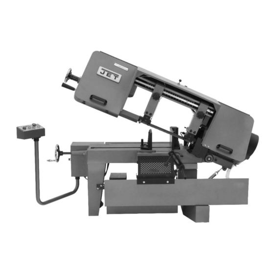
Operating Instructions and Parts Manual
10" x 16" Horizontal Band Saw
Models J-7020, J-7040
WALTER MEIER (Manufacturing) Inc.
427 New Sanford Road
LaVergne, Tennessee 37086
Part No. M-414472
Ph.: 800-274-6848
Revision C1 04/2013
www.waltermeier.com
Copyright © 2013 Walter Meier (Manufacturing) Inc.
Advertisement
Table of Contents

Subscribe to Our Youtube Channel
Related Manuals for Jet J-7020


Summary of Contents for Jet J-7020
- Page 1 This .pdf document is bookmarked Operating Instructions and Parts Manual 10” x 16” Horizontal Band Saw Models J-7020, J-7040 WALTER MEIER (Manufacturing) Inc. 427 New Sanford Road LaVergne, Tennessee 37086 Part No. M-414472 Ph.: 800-274-6848 Revision C1 04/2013 www.waltermeier.com Copyright © 2013 Walter Meier (Manufacturing) Inc.
-
Page 2: Warranty And Service
Walter Meier Authorized Service Centers can authorize warranty repair, assist you in obtaining parts, or perform routine maintenance and major repair on your JET® tools. For the name of an Authorized Service Center in your area call 1-800-274-6848. -
Page 3: Table Of Contents
14.2.1 Head (J-7020/7040) – Exploded View ....................24 14.2.2 Head (J-7020/7040) – Parts List ......................25 15.0 Electrical Connections ..........................28 15.1 Electrical Connections – single phase only (model J-7020) ..............28 15.2 Electrical Connections – three phase only (model J-7040) ..............29... -
Page 4: Safety Warnings
Read and follow these simple rules for best results and full benefits from your machine. Used properly, 14. Keep work area clean. Cluttered areas invite JET machinery is among the best in design and accidents. safety. However, any machine used improperly can 15. - Page 5 18. Keep hands in sight and clear of all moving parts motor shall be started and you should allow and cutting surfaces. the saw to achieve full speed before bringing the saw blade into contact with the workpiece. 19. All visitors should be kept at a safe distance from the work area.
-
Page 6: About This Machine And Manual
This manual is provided by Walter Meier (Manufacturing) Inc. covering the safe operation and maintenance procedures for the J-7020 and J-7040 Horizontal Band Saws. This manual contains instructions on installation, safety precautions, general operating procedures, maintenance instructions and parts breakdown. Your machine has been designed and constructed to provide years of trouble-free operation if used in accordance with the instructions as set forth in this document. - Page 7 Speeds and capacities: Blade speed ......variable 100-350 fpm ..... variable 100-350 fpm ... variable 100-350 fpm Round capacity at 90-degrees ....10” (255mm) ......10” (255mm) ......10” (255mm) Round capacity at 45-degrees ....10” (255mm) ......10” (255mm) ......10” (255mm) Rectangular capacity at 90-degrees ..7”x16”/10”x10”...
-
Page 8: Machine Setup
It is recommended that the single phase band saw downward is controlled by a hydraulic feed (model J-7020), when operated on 115 volt power, rate control located on the top, rear of the saw be connected to a dedicated 30 amp circuit with a head (see Figure 3). -
Page 9: Raising/Lowering Saw Head
8.4 Controlling the cut: Hydraulic knob turned counterclockwise. Speed decreases when the knob is turned clockwise. feed control 2. A placard on the drive belt guard provides The weight of the saw arm provides all the force recommended speeds for various materials. needed to move the saw blade through the workpiece. -
Page 10: Blade Selection
However, the following procedure will be adequate for break-in of JET-supplied blades on 2. Turn the locking handle on the round, angle- lower alloy ferrous materials. -
Page 11: Installation And Adjustment Of Work Stop
vise jaw. Put the rear end of the workpiece 4. Install the locking knob in the hole in the side against the angle-setting block. of the stop L-bracket. 4. Turn clamping hand wheel clockwise until the 5. Slide the assembled stop L-bracket onto the left vise jaw is parallel with the workpiece. -
Page 12: Coolant Flow
7. DO NOT DROP THE SAW HEAD OR FORCE used properly or if the blade is correctly welded. THE CUT. Let the weight of the saw head (See Figure 10 for location of blade tracking provide the cutting force. adjustment screws.) 8. -
Page 13: Blade Guide Bearing Adjustment
length of paper between the blade and the blade guide bearings are adjusted at the factory. wheel as shown in Figure 11. The paper They should rarely require adjustment. When should not be cut as it passes between the adjustment is required, adjust immediately. Failure wheel shoulder and the blade. -
Page 14: Test Cutting To Verify Adjustment Accuracy
(The blade should be in a vertical position between the bearings. (See Figure 13.) 5. Tighten the center locking screw with an Allen wrench while holding the eccentric bushing in position with the 3/4-inch wrench. 6. Use the same procedure to adjust the other guide bearing. -
Page 15: Lubrication
cuttings and other material that would cause from the idler and drive wheels. Remove the damage. blade from between the blade guides. 4. Clean the chip sludge from the coolant tank. 2. Install the new blade between the blade guide The frequency should be determined by how bearings and the carbide blade guides. -
Page 16: Replacing Drive Motor
12.8 Replacing idler wheel or idler 12.5 Replacing drive motor bearing 1. Disconnect the motor from all electrical power. 1. Remove the saw blade (see sect. 12.3, Unplug the motor if it is plugged into a socket. Changing blades). Shut off the power to the branch and remove the connection to the junction box if the motor 2. -
Page 17: Replacing Carbide Blade Guide
2. Insert the capscrew into the new bearing. 12.10 Replacing carbide blade guide Replace the spring washer onto the capscrew and re-install into the floating block. Refer to Figure 17. 3. If re-adjustment is necessary, loosen the pivot 1. Remove the cap screw and remove the capscrew and move the floating block so that carbide guide. -
Page 18: Troubleshooting The J-7020/7040 Band Saws
13.0 Troubleshooting the J-7020/7040 Band Saws Symptom Possible Cause Correction Excessive blade Material loose in vise. Clamp work securely. breakage Incorrect speed or feed. Check machinist’s handbook for speed/feed appropriate for the material being cut. Teeth too coarse for material. -
Page 19: Replacement Parts
Symptom Possible Cause Correction Unusual wear on Blade guides worn Replace blade guides. side/back of blade Blade guide bearings not adjusted. Adjust blade guide bearings. Blade guide bearing bracket is loose. Tighten blade guide bearing bracket. Teeth missing/ripped Blade tooth pitch too coarse for Use blade with finer tooth pitch. -
Page 20: Base (J-7020/7040) - Exploded View
14.1.1 Base (J-7020/7040) – Exploded View... -
Page 21: Base (J-7020/7040) - Parts List
14.1.2 Base (J-7020/7040) – Parts List Index No Part No Description Size Qty 1 ....J-5712251 ....Foot, Left......................1 2 ....J-5712261 ....Foot, Right ..................... 1 3 ....J-5712271 ....Coolant Reservoir ..................1 3-1 ..... 5519485 ....Stopper (PT 3/8") ................... 1 4 .... - Page 22 70-1 ... 5519499 ....Knob ......................1 70-2 ... 5519500 ....Plane......................1 71 ....5507542 ....Overload, Model J-7020 (115V,1-ph) ............1 ....5713031 ....Overload, Model J-7020 (220V,1-ph) ............1 ....5512660 ....Overload, Model J-7040 (220V,3-ph) ............1 ....
- Page 23 (For Saw Serial No.12020250 and Earlier) ....5516855N....Coolant Pump Switch ...... 1 (For Saw Serial No.12020251 and Later) ....STRIPE-1-3/4 .... JET stripe (not shown) ..............sold per ft. *** Spring Changed since Dec. '96 Piston/Seal Kit 5512787 E-M valve &...
-
Page 24: Head (J-7020/7040) - Exploded View
14.2.1 Head (J-7020/7040) – Exploded View... -
Page 25: Head (J-7020/7040) - Parts List
Qty 79 ....5713381 ....Screw ............... 1/4" x 3/8"...... 4 80 ....J-5713391 ....Blade Wheel Cover ..................1 80-1 ... 5518109 ....Label, JET Logo..................... 1 80-2 ... 5519511 ....Label, Blade Size ..................1 80-3 ... - Page 26 Index No Part No Description Size Qty 115 .... 5713761 ....Washer ..............1/2" ........ 1 116 .... 5713771 ....Washer ..............5/16" ......2 118 .... 5713781 ....Screw ............... M16 x 30 ....... 3 119 .... 5713791 ....Screw ............... 1/2" x 3/4"...... 1 120 ....
- Page 27 Index No Part No Description Size Qty 160 .... 5714241 ....Blade Wheel Shaft ..................1 161 .... 5714251 ....Threaded Nut ....................1 161-1 ..5519690 ....Pan Head Screw ............M6x12 ......2 161-2 ..5519691 ....Tension Scale ....................1 162 ....
-
Page 28: Electrical Connections
15.0 Electrical Connections 15.1 Electrical Connections – single phase only (model J-7020) Figure 20: Model J-7020 wiring diagram Figure 21: Connection diagram for 1PH motor... -
Page 29: Electrical Connections - Three Phase Only (Model J-7040)
15.2 Electrical Connections – three phase only (model J-7040) Figure 22: Model J-7040 wiring diagram Figure 23: Connection diagram for 3PH motor... - Page 30 This page intentionally left blank.
- Page 31 This page intentionally left blank.
- Page 32 WALTER MEIER (Manufacturing) Inc. 427 New Sanford Road LaVergne, Tennessee 37086 Phone: 800-274-6848 www.jetttools.com www.waltermeier.com...
Need help?
Do you have a question about the J-7020 and is the answer not in the manual?
Questions and answers