
Related Manuals for Canvas Anderson Credenza


Summary of Contents for Canvas Anderson Credenza
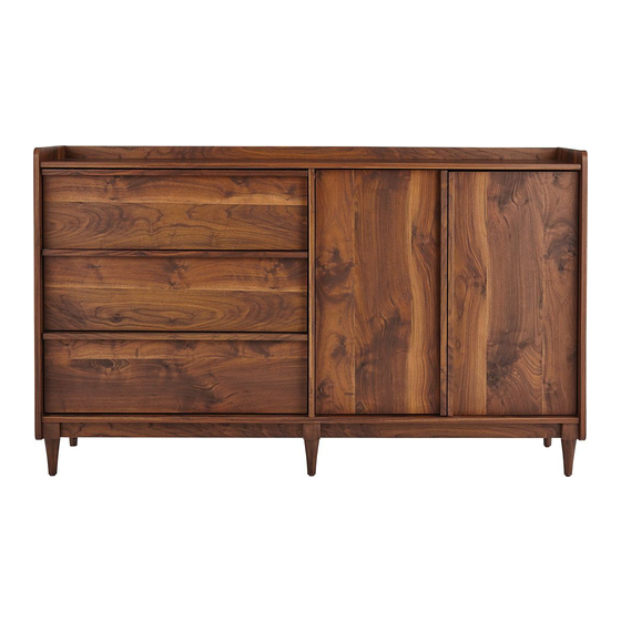
- Page 1 ANDERSON CREDENZA MODEL NO. 068-7827-2 ASSEMBLY INSTRUCTIONS Toll-free 1-888-670-6684 IMPORTANT: Please read this manual carefully before beginning assembly of this product. Keep this manual for future reference.
- Page 2 MODEL NO. 068-7827-2 Important Safety Instructions Parts List Assembly 7-31 Warranty Warning! To reduce the risk of serious injury, read the following safety instructions before assembling and using the dining table. • This product is intended for domestic indoor use only. •...
-
Page 3: Table Of Contents
Right End - 1 Brace - 2 Left End - 1 Skirt - 4 Upright - 1 Back - 1 Top - 1 Shelf - 1 Bottom - 1 Right Front/Left Rear Foot - 2 Back Rail - 1 Left Front/Right Rear Foot - 2... - Page 4 MODEL NO. 068-7827-2 Top Drawer Back - 1 Center Foot - 2 Door - 2 Right Drawer Side - 2 Left Drawer Side - 2 Top Drawer Front - 1 Drawer Front - 2 Drawer Bottom - 2 Top Right Drawer Side - 1 Drawer Back - 2 Top Left Drawer Side - 1 Drawer Brace - 2...
- Page 5 Extension Set shown separated Extension Rail - 6 Long Wood Dowel - 40 Extension Slide - 6 Short Wood Dowel - 4 Large Hidden Cam- 38 Cover Card - 1 Small Hidden Cam - 12 Metal Pin/Rubber Sleeve Set - 4 Angled head Angled Head Cam Screw - 38 Drawer Bracket Set - 2...
- Page 6 MODEL NO. 068-7827-2 Hinge - 4 Black 1-1/2" Flat Head Screw - 30 Bumper - 2 Black 13/16" Wafer Head Screw - 6 Washer - 4 Black 1/2" Wafer Head Screw - 4 Ballast - 1 Black 1/2" Pan Head Screw - 36 Nail - 48 Silver 1/2"...
- Page 7 Step 1 Requires D, 5, 7 NOTE: Two people are needed to build this unit. Turn two ANGLED CAM SCREWS (5) into the TOP (D). Insert four LONG WOOD DOWELS (7) into the short edges of the TOP (D). Angled head Surface with more holes Rounded edge Angled head...
- Page 8 MODEL NO. 068-7827-2 Step 2 Requires D, F, 7, 19 Insert three LONG WOOD DOWELS (7) into the BACK RAIL (F). Fasten the TOP (D) to the BACK RAIL (F). Use four BLACK 1-1/2" FLAT HEAD SCREWS (19). NOTE: Be sure the LONG WOOD DOWELS in the BACK RAIL insert into the TOP. Surface with larage holes Surface with CAM SCREWS...
- Page 9 Step 3 Requires E, 5, 7 Turn fourteen ANGLED CAM SCREWS (5) into the exact holes shown in the BOTTOM (E). Insert six LONG WOOD DOWELS (7) into the short edges of the BOTTOM (E). Angled head Surface with more holes Finished edge Angled head...
- Page 10 MODEL NO. 068-7827-2 Step 4 Requires H, K, L, M, 3, 5, 7 Turn four ANGLED CAM SCREWS (5) into the exact holes shown in the FEET (K, L, and M). Insert four LONG WOOD DOWELS (7) into the FEET (K, L, and M). Insert two LONG WOOD DOWELS (7) into the SKIRTS (H).
- Page 11 Step 5 Requires E, H, K, L, M, 3, 7 Insert six LONG WOOD DOWELS (7) into the FEET (K, L, and M). Insert fourteen LARGE HIDDEN CAMS (3) into the SKIRTS (H) and FEET (K, L, and M). Fasten the SKIRTS (H) and FEET (K, L, and M) to the BOTTOM (E). Tighten fourteen LARGE HIDDEN CAMS.
-
Page 12: Right End
MODEL NO. 068-7827-2 Step 6 Requires A, B, 1, 5, 12, 22 Turn twelve ANGLED CAM SCREWS (5) into the exact holes in the ENDS (A and B). Fasten two HINGE BRACKETS (12) to the RIGHT END (A). Use the four SCREWS in the HINGE BRACKETS. -
Page 13: Upright
Step 7 Requires C, 1, 5, 7, 12, 22 First, fasten two HINGE BRACKETS (12) to the UPRIGHT (C). Use the four SCREWS in the HINGE BRACKETS. Then, fl ip the UPRIGHT over. Turn two ANGLED CAM SCREWS (5) into the exact holes in the UPRIGHT (C). Insert fi... - Page 14 MODEL NO. 068-7827-2 Step 8 Requires C, D, 3 Insert two LARGE HIDDEN CAMS (3) into the UPRIGHT (C). Fasten the UPRIGHT (C) to the TOP (D). Tighten two LARGE HIDDEN CAMS. NOTE: Be sure the LONG WOOD DOWELS in the UPRIGHT insert into the TOP. The arrow must point toward the edge of the board.
-
Page 15: Bottom
Step 9 Requires E, 19 Fasten the BOTTOM (E) to the UPRIGHT (C). Use two BLACK 1-1/2" FLAT HEAD SCREWS (19). NOTE: Be sure the LONG WOOD DOWELS in the UPRIGHT insert into the BOTTOM. Caution Do not stand the unit upright without the BACK fastened. -
Page 16: Back Rail
MODEL NO. 068-7827-2 Step 10 Requires A, 3, 8 Insert two SHORT WOOD DOWELS (8) into the FEET (K and L). Insert fi ve LARGE HIDDEN CAMS (3) into the TOP (D), BOTTOM (E), and BACK RAIL (F). Fasten the RIGHT END (A) to the TOP (D), BOTTOM (E), and BACK RAIL (F). Tighten fi... -
Page 17: Brace
Step 11 Requires G, 3, 7 Insert four LONG WOOD DOWELS (7) into the ends of the BRACES (G). Insert two LARGE HIDDEN CAMS (3) into the BRACES (G). Fasten the BRACES (G) to the UPRIGHT (C). Tighten two LARGE HIDDEN CAMS. NOTE: Be sure the LONG WOOD DOWELS in the BRACES insert into the UPRIGHT. - Page 18 MODEL NO. 068-7827-2 Step 12 Requires B, 3, 8 Insert two SHORT WOOD DOWELS (8) into the FEET (K and L). Insert seven LARGE HIDDEN CAMS (3) into the TOP (D), BOTTOM (E), BACK RAIL (F), and BRACES (G). Fasten the LEFT END (B) to the TOP (D), BOTTOM (E), BACK RAIL (F), and BRACES (G). Tighten seven LARGE HIDDEN CAMS.
- Page 19 Step 13 Requires I, 15, 16, 17, 18 Unfold the BACK (I) and lay it over your unit. Make equal margins along all four edges of the BACK (I). Push on opposite corners of your unit if needed to make it "square". Fasten the BACK (I) to your unit using the NAILS (17).
- Page 20 MODEL NO. 068-7827-2 Step 14 Requires Q, R, 2, 22 Fasten two EXTENSION SLIDES (2) to the TOP DRAWER SIDES (Q and R). Use six BLACK 1/2" PAN HEAD SCREWS (22). Use these holes. Open end Open end Open end Angled edge...
-
Page 21: Top Drawer Bottom
Step 15 Requires Q, R, S, T, 19 Fasten the TOP DRAWER BOTTOM (S) to the TOP DRAWER BACK (T). Use four BLACK 1-1/2" FLAT HEAD SCREWS (19). Fasten the TOP DRAWER SIDES (Q and R) to the TOP DRAWER BOTTOM (S) and TOP DRAWER BACK (T). - Page 22 MODEL NO. 068-7827-2 Step 16 Requires 11, 14, 20 Peel the BUMPERS (14) from the card and place one in each front corner of the TOP DRAWER BOTTOM (S). Fasten the DRAWER BRACKET SETS (11) to the TOP DRAWER SIDES (Q and R) exactly as shown.
- Page 23 Step 17 Requires O, 21 Fasten the TOP DRAWER FRONT (O) to the DRAWER BRACKET SETS (11). Use four BLACK 1/2" WAFER HEAD SCREWS (21). Curved edge...
- Page 24 MODEL NO. 068-7827-2 Step 18 Requires U, V, 2, 22 Fasten two EXTENSION SLIDES (2) to the DRAWER SIDES (U and V). Use six BLACK 1/2" PAN HEAD SCREWS (22). Use these holes. Open end Open end Open end...
- Page 25 Step 19 Requires P, U, V, Y, 4, 6 Turn six STRAIGHT HEAD CAM SCREWS (6) into the DRAWER FRONT (P). Insert six SMALL HIDDEN CAMS (4) into the DRAWER SIDES (U and V) and DRAWER BRACE (Y). Fasten the DRAWER FRONT (P) to the DRAWER SIDES (U and V) and DRAWER BRACE (Y).
- Page 26 MODEL NO. 068-7827-2 Step 20 Requires W, X, 19 Slide the DRAWER BOTTOM (W) into the grooves in the DRAWER SIDES (U and V) and DRAWER FRONT (P). Fasten the DRAWER BACK (X) to the DRAWER SIDES (U and V) and DRAWER BRACE (Y).
- Page 27 Step 21 Requires N, 13, 23 Fasten the HINGES (13) to the DOORS (N). Use eight SILVER 1/2" FLAT HEAD SCREWS (23).
- Page 28 MODEL NO. 068-7827-2 Step 22 Requires O, P Carefully stand your unit upright and place in its fi nal location. To insert a drawer into your unit, line up the EXTENSION SLIDES on the drawer with the EXTENSION RAILS on the unit and push the drawer into the unit until the drawer is fully inserted.
- Page 29 Step 23 Requires J, 10 Push the RUBBER SLEEVES (10) over the METAL PINS (10). Insert the METAL PINS into the hole locations of your choice in the RIGHT END (A) and UPRIGHT (C). Set the ADJUSTABLE SHELF (J) onto the METAL PINS.
- Page 30 MODEL NO. 068-7827-2 Step 24 Requires N Fasten the HINGES on the DOORS (N) to the HINGE BRACKETS on the RIGHT END (A) and UPRIGHT (C). Refer to the diagrams. 50 lbs. 25 lbs. 15 lbs. 30 lbs. 25 lbs. 25 lbs.
- Page 31 Step 25 Requires 9, 99 Peel a sticker from the COVER CARD (9) and place onto each visible HIDDEN CAM. We recommend using the FURNITURE TIPPING RESTRAINT KITS (99) for added stability. Fasten two brackets to the back edge of the TOP (D) using the 5/8" screws as shown. NOTE: You will use the two nail holes in the BACK that were not used in Step 13.
- Page 32 MODEL NO. 068-7827-2 1-YEAR LIMITED WARRANTY This CANVAS™ product carries a one (1) year warranty against defects in workmanship and materials. Trileaf Distribution agrees to replace the defective product free of charge within the stated warranty period, when returned by the original purchaser with proof of purchase. This product is not guaranteed against wear or breakage due to misuse and/or abuse.
- Page 33 BUFFET ANDERSON N° DE MODÈLE : 068-7827-2 CONSIGNES D’ASSEMBLAGE Numéro sans frais : 1 888 670-6684 IMPORTANT : Veuillez lire attentivement ce guide avant de procéder à l’assemblage de ce produit. Conservez ce guide aux fi ns de consultation ultérieure.
- Page 34 N° DE MODÈLE : 068-7827-2 Consignes de sécurité importantes Liste des pièces 35-38 Assemblage 39-63 Garantie Avertissement! Pour réduire le risque de blessures graves, lisez les consignes de sécurité suivantes avant d’assembler et d’utiliser la table. • Ce produit est uniquement destiné à un usage domestique et doit être utilisé à l’intérieur. •...
- Page 35 Côté droit - 1 Entretoise - 2 Côté gauche - 1 Jupe - 4 Partie verticale - 1 Arrière - 1 Dessus - 1 Tablette - 1 Fond - 1 Pied avant droit/arrière gauche - 2 Traverse arrière - 1 Pied avant gauche/arrière droit - 2...
- Page 36 N° DE MODÈLE : 068-7827-2 Arrière du tiroir supérieur - 1 Pied central - 2 Porte - 2 Côté du tiroir droit - 2 Côté du tiroir gauche - 2 Avant du tiroir supérieur - 1 Avant du tiroir - 2 Fond du tiroir - 2 Côté...
- Page 37 Ensemble de rallonges montré séparément Traverse pour les rallonges - 6 Long goujon en bois - 40 Coulisse des rallonges - 6 Goujon court en bois - 4 Grande came dissimulée- 38 Carte d’autocollants - 1 Ensemble de tiges de métal/gaines en Petite came dissimulée - 12 caoutchouc - 4 Tête à...
- Page 38 N° DE MODÈLE : 068-7827-2 Charnière - 4 Vis à tête plate noire de 1 ½ po - 30 Tampon - 2 Vis à tête mince noire de 13/16 po - 6 Rondelle - 4 Vis à tête mince noire de 1/2 po - 4 Vis à...
- Page 39 Étape 1 Pièces requises : D, 5, 7 REMARQUE : Deux personnes sont nécessaires pour monter cette unité. Tourner deux VIS DE CAME À ANGLE (5) dans la PARTIE SUPÉRIEURE (D). Insérer quatre LONGS GOUJONS EN BOIS (7) dans les bords courts de la PARTIE SUPÉRIEURE (D).
- Page 40 N° DE MODÈLE : 068-7827-2 Étape 2 Pièces requises : D, F, 7, 19 Insérer trois LONGS GOUJONS EN BOIS (7) dans la TRAVERSE ARRIÈRE (F). Attacher la PARTIE SUPÉRIEURE (D) à la TRAVERSE ARRIÈRE (F). Utiliser quatre VIS À TÊTE PLATE NOIRES de 1 ½...
- Page 41 Étape 3 Pièces requises : E, 5, 7 Tourner 14 VIS DE CAME À ANGLE (5) dans les trous montrés dans la PARTIE INFÉRIEURE (E). Insérer six LONGS GOUJONS EN BOIS (7) dans les bords courts de la PARTIE INFÉRIEURE (E). Tête à...
- Page 42 N° DE MODÈLE : 068-7827-2 Étape 4 Pièces requises : H, K, L, M, 3, 5, 7 Tourner quatre VIS DE CAME À ANGLE (5) dans les trous montrés dans le PIED (K, L et M). Insérer quatre LONGS GOUJONS EN BOIS (7) dans le PIED (K, L et M). Insérer deux LONGS GOUJONS EN BOIS (7) dans les JUPES (H).
- Page 43 Étape 5 Pièces requises : E, H, K, L, M, 3, 7 Insérer six LONGS GOUJONS EN BOIS (7) dans les PIEDS (K, L et M). Insérer 14 GRANDES CAMES DISSIMULÉES (3) dans les JUPES (H) et les PIEDS (K, L et M). Attacher les JUPES (H) et les PIEDS (K, L et M) à...
- Page 44 N° DE MODÈLE : 068-7827-2 Étape 6 Pièces requises : A, B, 1, 5, 12, 22 Tourner 12 VIS DE CAME À ANGLE (5) dans les trous montrés dans les EXTRÉMITÉS (A et B) Attacher deux SUPPORTS DE CHARNIÈRE (12) à l’EXTRÉMITÉ DROITE (A). Utiliser quatre VIS dans les SUPPORTS DE CHARNIÈRE Séparer les COULISSES DE RALLONGE (2) des TRAVERSES POUR RALLONGES (1) comme montré...
- Page 45 Étape 7 Pièces requises : C, 1, 5, 7, 12, 22 Premièrement, attacher deux SUPPORTS DE CHARNIÈRE (12) à la PARTIE VERTICALE (C) Utiliser les quatre VIS dans les SUPPORTS DE CHARNIÈRE. Tourner ensuite la PARTIE VERTICALE par-dessus. Tourner deux VIS DE CAME À ANGLE (5) dans les trous montrés dans la PARTIE VERTICALE (C).
- Page 46 N° DE MODÈLE : 068-7827-2 Étape 8 Pièces requises : C, D, 3 Insérer deux GRANDES CAMES DISSIMULÉES (3) dans la PARTIE VERTICALE (C). Attacher la PARTIE VERTICALE (C) à la PARTIE SUPÉRIEURE (D). Serrer deux GRANDES CAMES DISSIMULÉES. REMARQUE : Veiller à ce que les LONGS GOUJONS EN BOIS dans la PARTIE VERTICALE s’insèrent dans la PARTIE SUPÉRIEURE.
- Page 47 Étape 9 Pièces requises : E, 19 Attacher la PARTIE INFÉRIEURE (E) à la PARTIE VERTICALE (C). Utiliser deux VIS À TÊTE PLATE NOIRES de 1 ½ po (19). REMARQUE : Veiller à ce que les LONGS GOUJONS EN BOIS dans la PARTIE VERTICALE s’insèrent dans la PARTIE INFÉRIEURE.
- Page 48 N° DE MODÈLE : 068-7827-2 Étape 10 Pièces requises : A, 3, 8 Insérer deux COURTS GOUJONS EN BOIS (8) dans les PIEDS (K et L). Insérer cinq GRANDS GOUJONS EN BOIS (3) dans la PARTIE SUPÉRIEURE (D), la PARTIE INFÉRIEURE (E) et la TRAVERSE ARRIÈRE (F). Attacher l’EXTRÉMITÉ...
- Page 49 Étape 11 Pièces requises : G, 3, 7 Insérer quatre LONGS GOUJONS EN BOIS (7) dans les extrémités des entretoises (G). Insérer deux GRANDES CAMES DISSIMULÉES (3) dans les ENTRETOISES (G). Attacher les ENTRETOISES (G) à la PARTIE VERTICALE (C). Serrer deux GRANDES CAMES DISSIMULÉES.
- Page 50 N° DE MODÈLE : 068-7827-2 Étape 12 Pièces requises : B, 3, 8 Insérer deux COURTS GOUJONS EN BOIS (8) dans les PIEDS (K et L). Insérer sept GRANDS GOUJONS EN BOIS (3) dans la PARTIE SUPÉRIEURE (D), la PARTIE INFÉRIEURE (E), la TRAVERSE ARRIÈRE (F) et les CHARNIÈRES (G). Attacher l’EXTRÉMITÉ...
- Page 51 Étape 13 Pièces requises : I, 15, 16, 17, 18 Déplier l’ARRIÈRE (I) et l’étendre sur l’unité. Faire des marges égales le long des quatre bords de l’ARRIÈRE (I). Pousser sur les coins opposés de l’unité au besoin pour qu’elle soit « carrée ». Attacher l’ARRIÈRE (I) à...
- Page 52 N° DE MODÈLE : 068-7827-2 Étape 14 Pièces requises : Q, R, 2, 22 Attacher deux COULISSES DE RALLONGE (2) aux CÔTÉS DU TIROIR SUPÉRIEUR (Q et R). Utiliser six VIS À TÊTE CYLINDRIQUE BOMBÉE NOIRES de ½ po (22). Utiliser ces trous.
- Page 53 Étape 15 Pièces requises : Q, R, S, T, 19 Attacher le BAS DU TIROIR SUPÉRIEUR (S) à l’ARRIÈRE DU TIROIR SUPÉRIEUR (T). Utiliser quatre VIS À TÊTE PLATE NOIRES de 1 ½ po (19). Attacher les CÔTÉS DU TIROIR SUPÉRIEUR (Q et R) au BAS DU TIROIR SUPÉRIEUR (S) et à...
- Page 54 N° DE MODÈLE : 068-7827-2 Étape 16 Pièces requises : 11, 14, 20 Décoller les TAMPONS (14) de la carte et en placer un à chaque coin avant du BAS DU TIROIR SUPÉRIEUR (S). Attacher les ENSEMBLES DE CHARNIÈRES DE TIROIR (11) aux CÔTÉS DU TIROIR SUPÉRIEUR (Q et R) exactement comme il est montré.
- Page 55 Étape 17 Pièces requises : O, 21 Attacher l’AVANT DU TIROIR SUPÉRIEUR (O) aux ENSEMBLES DE CHARNIÈRES DE TIROIR (11). Utiliser quatre VIS À TÊTE MINCE NOIRES de ½ po (21). Bord courbé...
- Page 56 N° DE MODÈLE : 068-7827-2 Étape 18 Pièces requises : U, V, 2, 22 Attacher deux COULISSES DE RALLONGE (2) aux CÔTÉS DU TIROIR (U et V). Utiliser six VIS À TÊTE CYLINDRIQUE BOMBÉE NOIRES de ½ po (22). Utiliser ces trous. Extrémité...
- Page 57 Étape 19 Pièces requises : P, U, V, Y, 4, 6 Tourner six VIS DE CAME À TÊTE DROITE (6) dans l’AVANT DU TIROIR (P). Insérer six PETITES CAMES DISSIMULÉES (4) dans les CÔTÉS DU TIROIR (U et V) et dans l’ENTRETOISE DU TIROIR (Y).
- Page 58 N° DE MODÈLE : 068-7827-2 Étape 20 Pièces requises : W, X, 19 Faire glisser le BAS DU TIROIR (W) dans les rainures sur les CÔTÉS DU TIROIR (U et V) et à l’AVANT DU TIROIR (P). Attacher l’ARRIÈRE DU TIROIR (P) aux CÔTÉS DU TIROIR (U et V) et à l’ENTRETOISE DU TIROIR (Y).
- Page 59 Étape 21 Pièces requises : N, 13, 23 Attacher les CHARNIÈRES (13) aux PORTES (N). Utiliser huit VIS À TÊTE PLATE ARGENTÉES de ½ po (23).
- Page 60 N° DE MODÈLE : 068-7827-2 Étape 22 Pièces requises : O, P Relever prudemment l’unité et la placer à l’endroit prévu. Pour insérer un tiroir dans l’unité, aligner les COULISSES DE RALLONGE sur le tiroir avec les TRAVERSES DE RALLONGE sur l’unité et pousser le tiroir dans l’unité jusqu’à ce que le tiroir soit entièrement inséré.
- Page 61 Étape 23 Pièces requises : J, 10 Pousser les GAINES DE CAOUTCHOUC (10) sur les TIGES DE MÉTAL (10). Insérer les TIGES DE MÉTAL dans les trous souhaités à l’EXTRÉMITÉ DROITE (A) et dans la PARTIE VERTICALE (C). Placer la TABLETTE AJUSTABLE (J) sur les TIGES DE MÉTAL.
- Page 62 N° DE MODÈLE : 068-7827-2 Étape 24 Pièces requises : N Attacher les CHARNIÈRES sur les PORTES (N) aux SUPPORTS DE CHARNIÈRE à l’EXTRÉMITÉ DROITE (A) et sur la PARTIE VERTICALE (C). Consulter les diagrammes. 22,6 kg (50 lb) 11,3 kg (25 lb) 6,8 kg (15 lb)
- Page 63 Étape 25 Pièces requises : 9, 99 Décoller un autocollant de la CARTE D’AUTOCOLLANTS (9) et le placer sur chaque CAME DISSIMULÉE visible. Nous recommandons d’utiliser les TROUSSES ANTIBASCULEMENT (99) pour une meilleure stabilité. Attacher deux supports au bord arrière de la PARTIE SUPÉRIEURE (D) au moyen des vis de 5/8 po comme il est montré.
- Page 64 N° DE MODÈLE : 068-7827-2 GARANTIE LIMITÉE DE 1 AN Cet article CANVAS comporte une garantie de un (1) an contre les défauts de fabrication et de matériau(x). Distribution Trifeuil consent à remplacer l’article défectueux sans frais lorsqu’il est retourné, accompagné de la preuve d’achat, par l’acquéreur initial au cours de la période de garantie convenue.
Need help?
Do you have a question about the Anderson Credenza and is the answer not in the manual?
Questions and answers