
Subscribe to Our Youtube Channel
Related Manuals for Canvas OLSEN 168-0072-0


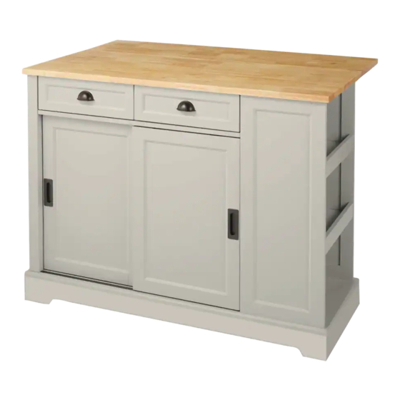
Summary of Contents for Canvas OLSEN 168-0072-0
- Page 1 OLSEN KITCHEN ISLAND WITH LEAF MODEL NO. 168-0072-0 ASSEMBLY INSTRUCTIONS HAVING TROUBLE? TOLL-FREE: 1-888-670-6684...
- Page 2 Holiday Decor and Outdoor Living, • Check all screws periodically for tightness. When required, tighten them again. CANVAS makes it easy to refresh your • For maximum weight capacity of each part, see page 36 of Manual. your unique style and the way you live.
- Page 3 PARTS LIST EXPLODED VIEW ITEM DESCRIPTION QUANTITY Back Top Panel Front Top Panel Left Side Panel Right Side Panel Brace Back Panel Rail Track Strip Divider Left Front Trim Bottom Support wood Right Adjustable Shelves Right Side Trim Left Door Panel Right Door Panel Right Front Panel Adjustable Shelf...
- Page 4 PARTS LIST EXPLODED VIEW ITEM DESCRIPTION QUANTITY Wood Dowels Ø7.8 x 30 mm Cam Bolts (big) Cams (big) Wood Dowels Ø5.8 x 30 mm Cam Bolts (small) Cams (small) Extension Slides Extension Rails With Stopper Handles Hinges Handles Screws Ø3.5 x 12 mm Screws Ø4 x 14 mm Screws Ø4 x 35 mm Hexagon wrench...
- Page 5 STEP-BY-STEP INSTRUCTIONS NOTE: Dip a little glue to the wood dowel before insert it to the STEP 2 hole of panel REQUIRES C, 1, 2, 21, 22 STEP 1 Turn one CAM BOLT (BIG) (2) and insert eight WOOD DOWELS Ø7.8 x 30 MM (1) REQUIRES D, 1, 2, 8, 12 into the exact holes in the LEFT SIDE PANEL (C).
- Page 6 STEP-BY-STEP INSTRUCTIONS STEP 3 STEP 4 REQUIRES G, I, 1, 2 REQUIRES C, G, 14 Insert two WOOD DOWELS Ø7.8 x 30 MM (1) into the exact holes in the RAIL Fasten RAIL TRACK STRIP (G) to the LEFT SIDE PANEL (C). Use three SCREWS TRACK STRIP (G) and turn three CAM BOLTS (BIG) (2) into the exact holes in Ø4 x 35 MM (14).
- Page 7 STEP-BY-STEP INSTRUCTIONS STEP 5 STEP 6 REQUIRES C, I, 3 REQUIRES C, 8, 12 Insert three CAMS (BIG) (3) into the LEFT SIDE PANEL (C). Fasten EXTENSION RAIL WITH STOPPER (8) to the LEFT SIDE PANEL (C). Use three SCREWS Ø3.5 x 12 MM (12). Fasten the LEFT FRONT TRIM (I) to the LEFT SIDE PANEL (C).
- Page 8 STEP-BY-STEP INSTRUCTIONS STEP 7 STEP 8 REQUIRES E, 1 REQUIRES C, D, E, 3 Insert two WOOD DOWELS Ø7.8 x 30 MM (1) into the short edges of the BRACE (E). Insert two CAMS (BIG) (3) into the BRACE (E). Fasten the LEFT SIDE PANEL (C) and RIGHT SIDE PANEL (D) to the BRACE (E).
- Page 9 STEP-BY-STEP INSTRUCTIONS STEP 9 STEP 10 REQUIRES F, 1, 2 REQUIRES C, D, F, 3 Insert six WOOD DOWELS Ø7.8 x 30 MM (1) and six CAM BOLTS (BIG) (2) into the Insert six CAMS (BIG) (3) into LEFT SIDE PANEL (C) and RIGHT SIDE PANEL (D). BACK PANEL (F).
- Page 10 STEP-BY-STEP INSTRUCTIONS STEP 11 STEP 12 REQUIRES P, 1, 2 REQUIRES D, P, 3 Insert two WOOD DOWELS Ø7.8 x 30 MM (1) and three CAM BOLTS (BIG) (2) to the Insert three CAM (BIG) (3) into RIGHT SIDE PANEL (D). RIGHT FRONT PANEL (P).
- Page 11 STEP-BY-STEP INSTRUCTIONS STEP 13 STEP 14 REQUIRES J, X, 16 REQUIRES C, D, F, J, P, 16 Connect the SUPPORT FOOT (X) with the BOTTOM (J). Use one SCREW Fasten BOTTOM (J) to LEFT SIDE PANEL (C), RIGHT SIDE PANEL (D), RIGHT Ø5 x 50 MM (16).
- Page 12 STEP-BY-STEP INSTRUCTIONS STEP 15 STEP 16 REQUIRES H, 1, 8, 12 REQUIRES E, H, 16 EXTENSION RAILS WITH STOPPER Fasten two S (8) to both sides of DIVIDER (H). Fasten DIVIDER (H) to BRACE (E). Use one SCREW Ø5 x 50 MM (16). Use six SCREWS Ø3.5 x 12 MM (12).
- Page 13 STEP-BY-STEP INSTRUCTIONS STEP 17 STEP 18 REQUIRES F, H, 16 REQUIRES A, B, K, 2, 10, 13, 15, 24, 25 Turn twelve CAM BOLTS (BIG) (2) into the exact holes in the FRONT TOP PANEL (B). Fasten BACK PANEL (F) to DIVIDER (H). Use one SCREW Ø5 x 50 MM (16). Connect two SUPPORT WOODS (K) with FRONT TOP PANEL (B), use two BOLTS M6 30 MM (24) and two FLAT WASHERS (25).
- Page 14 STEP-BY-STEP INSTRUCTIONS STEP 19 STEP 20 REQUIRES L, M, 1, 2 REQUIRES A, B, C, D, F, H, P, 3 Insert two WOOD DOWELS Ø7.8 x 30 MM (1) into the RIGHT ADJUSTABLE SHELF (L). Insert four CAMS (BIG) (3) into BACK PANEL (F), two CAMS (BIG) (3) into LEFT SIDE PANEL (C), two CAMS (BIG) (3) into RIGHT SIDE PANEL (D), two CAMS (BIG) (3) into Turn two CAM BOLTS (BIG) (2) into the exact holes in the RIGHT SIDE TRIM (M).
- Page 15 STEP-BY-STEP INSTRUCTIONS STEP 21 STEP 22 REQUIRES L, M, 3 REQUIRES C, D, F, L, P, Q, 20 Insert two CAMS (BIG) (3) into the RIGHT ADJUSTABLE SHELF (L). Insert four SHELF SUPPORT (20) to the LEFT SIDE PANEL (C) and the RIGHT SIDE PANEL (D).
- Page 16 STEP-BY-STEP INSTRUCTIONS STEP 23 STEP 24 REQUIRES N, O, 11, 18, 23 REQUIRES E, J, N, O Fasten one HANDLE (11) to LEFT DOOR PANEL (N). Use two BOLTS M4 x 12 MM (18). Press down the stopper in the LEFT DOOR PANEL (N) and RIGHT DOOR PANEL (O). Set the door (the side with small wheel) into the BOTTOM (J), ensure the small wheel Fasten one HANDLE (11) to RIGHT DOOR PANEL (O).
- Page 17 STEP-BY-STEP INSTRUCTIONS STEP 25 STEP 26 REQUIRES R, S, 4, 7, 12 REQUIRES R, S, T, 17 Fasten one EXTENSION SLIDE (7) to the LEFT DRAWER SIDE (R). Use three SCREWS Fasten DRAWER BACK (T) to LEFT DRAWER SIDE (R) and RIGHT DRAWER SIDE Ø3.5 x 12 MM (12).
- Page 18 STEP-BY-STEP INSTRUCTIONS STEP 27 STEP 28 REQUIRES V, W, 5, 9, 19 REQUIRES R, S, T, U, V, W, 6 Turn four CAM BOLTS (SMALL) (5) into the exact holes in the LEFT DRAWER FACE Slide the DRAWER BOTTOM (U) into the grooves in the DRAWER SIDES (R and S) (V).
- Page 19 WARRANTY 1-YEAR LIMITED WARRANTY STEP 29 This CANVAS™ product carries a one (1 ) year warranty against defects in workmanship REQUIRES V, W and materials. Insert two drawers one by one into your unit, line up the extension slides on the...
- Page 20 Exclusively at Canadian Tire...
- Page 21 ÎLOT DE CUISINE AVEC ABATTANT OLSEN N° DE MODÈLE : 168-0072-0 INSTRUCTIONS D’ASSEMBLAGE DES DIFFICULTÉS? NUMÉRO SANS FRAIS : 1 888 670-6684...
- Page 22 OUTILS REQUIS Web pour nous faire part de votre expérience. Nous aimerions voir comment vous donnez vie à la marque CANVAS. Veuillez partager vos photos grâce au mot-clic #MonStyleCANVAS. Tournevis 2 personnes Serrez les vis à la main pour éviter tout dommage.
- Page 23 LISTE DES PIÈCES VUE ÉCLATÉE PIÈCE DESCRIPTION QUANTITÉ Panneau supérieur arrière Panneau supérieur avant Panneau latéral gauche Panneau latéral droit Renfort Panneau arrière Bloc pour rail Séparateur Bordure avant gauche Blocs Tablettes réglables droites Bordure latérale droite Porte gauche Porte droite Panneau avant droit Tablette réglable Côtés gauches de tiroir...
- Page 24 LISTE DES PIÈCES VUE ÉCLATÉE PIÈCE DESCRIPTION QUANTITÉ Goujons en bois de Ø7,8 x 30 mm Boulons à came (grands) Cames (grandes) Goujons en bois de Ø5,8 x 30 mm Boulons à came (petits) Cames (petites) Coulisses télescopiques Rails d’extension avec butée Poignées Charnières Poignées...
- Page 25 DIRECTIVES DÉTAILLÉES N.B. : Appliquez de la colle sur le bout de chaque goujon en ÉTAPE 2 bois avant de les insérer dans les trous du panneau. NÉCESSITE LES PIÈCES C, 1, 2, 21, 22 ÉTAPE 1 Vissez un BOULON À CAME (GRAND) (2) et insérez huit GOUJONS EN BOIS DE Ø7,8 X 30 MM (1) dans les trous appropriés du PANNEAU LATÉRAL GAUCHE (C).
- Page 26 DIRECTIVES DÉTAILLÉES ÉTAPE 3 ÉTAPE 4 NÉCESSITE LES PIÈCES G, I, 1, 2 NÉCESSITE LES PIÈCES C, G, 14 Insérez deux GOUJONS EN BOIS DE Ø7,8 X 30 MM (1) dans les trous Fixez le BLOC POUR RAIL (G) au PANNEAU LATÉRAL GAUCHE (C) à l’aide de appropriés du BLOC POUR RAIL (G) et vissez trois BOULONS À...
- Page 27 DIRECTIVES DÉTAILLÉES ÉTAPE 5 ÉTAPE 6 NÉCESSITE LES PIÈCES C, I, 3 NÉCESSITE LES PIÈCES C, 8, 12 Insérez trois CAMES (GRANDES) (3) dans le PANNEAU LATÉRAL GAUCHE (C). Fixez un RAIL D’EXTENSION AVEC BUTÉE (8) au PANNEAU LATÉRAL GAUCHE (C) à...
- Page 28 DIRECTIVES DÉTAILLÉES ÉTAPE 7 ÉTAPE 8 NÉCESSITE LES PIÈCES E, 1 NÉCESSITE LES PIÈCES C, D, E, 3 Insérez deux GOUJONS EN BOIS DE Ø7,8 X 30 MM (1) dans les bords courts du Insérez deux CAMES (GRANDES) (3) dans le RENFORT (E). RENFORT (E).
- Page 29 DIRECTIVES DÉTAILLÉES ÉTAPE 9 ÉTAPE 10 NÉCESSITE LES PIÈCES F, 1, 2 NÉCESSITE LES PIÈCES C, D, F, 3 Insérez six GOUJONS EN BOIS DE Ø7,8 X 30 MM (1) et six BOULONS À CAME Insérez six CAMES (GRANDES) (3) dans le PANNEAU LATÉRAL GAUCHE (C) et (GRANDS) (2) dans le PANNEAU ARRIÈRE (F).
- Page 30 DIRECTIVES DÉTAILLÉES ÉTAPE 11 ÉTAPE 12 NÉCESSITE LES PIÈCES P, 1, 2 NÉCESSITE LES PIÈCES D, P, 3 Insérez deux GOUJONS EN BOIS DE Ø7,8 X 30 MM (1) et trois BOULONS À Insérez trois CAMES (GRANDES) (3) dans le PANNEAU LATÉRAL DROIT (D). CAME (GRANDS) (2) dans le PANNEAU AVANT DROIT (P).
- Page 31 DIRECTIVES DÉTAILLÉES ÉTAPE 13 ÉTAPE 14 NÉCESSITE LES PIÈCES J, X, 16 NÉCESSITE LES PIÈCES C, D, F, J, P, 16 Fixez le PIED (X) au BAS (J) au moyen d’une VIS Ø5 x 50 mm (16). Fixez le BAS (J) au PANNEAU LATÉRAL GAUCHE (C), au PANNEAU LATÉRAL DROIT (D), au PANNEAU AVANT DROIT (P) et au PANNEAU ARRIÈRE (F) à...
- Page 32 DIRECTIVES DÉTAILLÉES ÉTAPE 15 ÉTAPE 16 NÉCESSITE LES PIÈCES H, 1, 8, 12 NÉCESSITE LES PIÈCES E, H, 16 Fixez un RAIL D’EXTENSION AVEC BUTÉE (8) de chaque côté du SÉPARATEUR Fixez le SÉPARATEUR (H) au RENFORT (E) à l’aide d’une VIS DE Ø5 X 50 MM (16). (H) à...
- Page 33 DIRECTIVES DÉTAILLÉES ÉTAPE 17 ÉTAPE 18 NÉCESSITE LES PIÈCES F, H, 16 NÉCESSITE LES PIÈCES A, B, K, 2, 10, 13, 15, 24, 25 Fixez le PANNEAU ARRIÈRE (F) au SÉPARATEUR (H) à l’aide d’une VIS DE Vissez douze BOULONS À CAME (GRANDS) (2) dans les trous appropriés du Ø5 X 50 MM (16).
- Page 34 DIRECTIVES DÉTAILLÉES ÉTAPE 19 ÉTAPE 20 NÉCESSITE LES PIÈCES A, B, C, D, F, H, P, 3 NÉCESSITE LES PIÈCES L, M, 1, 2 Insérez quatre CAMES (GRANDES) (3) dans le PANNEAU ARRIÈRE (F), deux CAMES Insérez deux GOUJONS EN BOIS DE Ø7,8 X 30 MM (1) dans la TABLETTE (GRANDES) (3) dans le PANNEAU LATÉRAL GAUCHE (C), deux CAMES (GRANDES) RÉGLABLE DROITE (L).
- Page 35 DIRECTIVES DÉTAILLÉES ÉTAPE 21 ÉTAPE 22 NÉCESSITE LES PIÈCES L, M, 3 NÉCESSITE LES PIÈCES C, D, F, L, P, Q, 20 Insérez deux CAMES (GRANDES) (3) dans la TABLETTE RÉGLABLE DROITE (L). Insérez quatre SUPPORT POUR TABLETTE (20) dans le PANNEAU LATÉRAL GAUCHE (C) et LE PANNEAU LATÉRAL DROIT (D).
- Page 36 DIRECTIVES DÉTAILLÉES ÉTAPE 23 ÉTAPE 24 NÉCESSITE LES PIÈCES N, O, 11, 18, 23 NÉCESSITE LES PIÈCES E, J, N, O Fixez une POIGNÉE (11) à la PORTE GAUCHE (N) à l’aide de deux BOULONS Appuyez sur la butée de la PORTE GAUCHE (N) et de la PORTE DROITE (O). M4 x 12 MM (18).
- Page 37 DIRECTIVES DÉTAILLÉES ÉTAPE 25 ÉTAPE 26 NÉCESSITE LES PIÈCES R, S, 4, 7, 12 NÉCESSITE LES PIÈCES R, S, T, 17 Fixez une COULISSE TÉLESCOPIQUE (7) à un CÔTÉ GAUCHE DE TIROIR (R) à Fixez l’ARRIÈRE DU TIROIR (T) à un CÔTÉ GAUCHE DE TIROIR (R) et à un CÔTÉ l’aide de trois VIS DE Ø3,5 X 12 MM (12).
- Page 38 DIRECTIVES DÉTAILLÉES ÉTAPE 27 ÉTAPE 28 NÉCESSITE LES PIÈCES V, W, 5, 9, 19 NÉCESSITE LES PIÈCES R, S, T, U, V, W, 6 Vissez quatre BOULONS À CAME (PETITS) (5) dans les trous appropriés du Glissez le BAS DU TIROIR (U) dans les rainures situées dans les CÔTÉS DU DEVANT DU TIROIR GAUCHE (V).
- Page 39 DIRECTIVES DÉTAILLÉES GARANTIE GARANTIE LIMITÉE DE 1 AN ÉTAPE 29 Cet article CANVAS est couvert par une garantie d’un (1) an contre les défauts de NÉCESSITE LES PIÈCES V, W matériaux et de fabrication. Insérez les deux tiroirs l’un après l’autre dans le meuble; alignez les coulisses Distribution Trifeuil consent à...
- Page 40 En exclusivité chez Canadian Tire...
Need help?
Do you have a question about the OLSEN 168-0072-0 and is the answer not in the manual?
Questions and answers
hi, need help to separate the extension rails and missing #23 pads. Thanks in advance for your assistance.
what is the color name of the product? Canvas OLSEN 168-0072-0