
Related Manuals for Canvas 068-7826-4


Summary of Contents for Canvas 068-7826-4
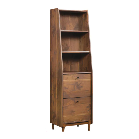
- Page 1 ANDERSON CABINET MODEL NO. 068-7826-4 ASSEMBLY INSTRUCTIONS Toll-free 1-888-670-6684 IMPORTANT: Please read this manual carefully before beginning assembly of this product. Keep this manual for future reference.
- Page 2 MODEL NO. 068-7826-4 Important Safety Instructions Parts List Assembly 7-25 Warranty Warning! To reduce the risk of serious injury, read the following safety instructions before assembling and using the dining table. • This product is intended for domestic indoor use only.
- Page 3 Right End - 1 Shelf - 1 Left End - 1 Large Shelf - 1 Top Molding - 1 Brace - 1 Top - 1 Bottom - 1 Small Shelf - 1 Right Front/Left Rear Foot - 2...
- Page 4 MODEL NO. 068-7826-4 Left Front/Right Rear Foot - 2 Drawer Bottom - 2 Bottom Brace - 2 Drawer Brace - 2 Left Drawer Side - 2 Drawer Front - 2 Drawer Back - 2 Back - 1 Right Drawer Side - 2...
- Page 5 Extension Set shown separated Extension Rail - 4 Long Wood Dowel - 30 Extension Slide - 4 Short Wood Dowel - 4 Large Hidden Cam- 36 Cover Card - 1 Small Hidden Cam - 12 Knob - 2 Angled head Angled Head Cam Screw - 36 Long File Glide - 2 Straight head...
- Page 6 MODEL NO. 068-7826-4 Front File Glide - 2 Black 2-9/16" Bolt - 8 File Hanger - 4 Black 1-1/2" Flat Head Screw - 12 Flat Washer - 8 Black 1-1/8" Flat Head Screw - 3 Ballast - 2 Black 7/8" Machine Screw - 2 Black 1/2"...
- Page 7 Step 1 Requires C, D, E, 7, 20 Fasten the TOP MOLDING (C) to the TOP (D). Use three BLACK 1-1/8" FLAT HEAD SCREWS (20). Insert eight LONG WOOD DOWELS (7) into the exact holes shown in the short edges of the TOP (D) and SMALL SHELF (E).
- Page 8 MODEL NO. 068-7826-4 Step 2 Requires F, G, 7 Insert eight LONG WOOD DOWELS (7) into the into the exact holes shown in the short edges of the SHELVES (F and G). Rounded edge Rounded edge...
- Page 9 Step 3 Requires I, 5, 7 Turn eight ANGLED CAM SCREWS (5) into the small holes in the BOTTOM (I). Insert four LONG WOOD DOWELS (7) into the edges of the BOTTOM (I). Angled head Finished Edge Angled head...
- Page 10 MODEL NO. 086-7826-4 Step 4 Requires J, K, L, 3, 5, 7 Turn two ANGLED HEAD CAM SCREWS (5) into the FEET (J and K). Insert two LONG WOOD DOWELS (7) into the FEET (J and K) and one into the long edge of the BOTTOM BRACE (L).
- Page 11 Step 5 Requires J, K, L, 3, 7 Insert four LONG WOOD DOWELS (7) into the BOTTOM (I). Insert eight LARGE HIDDEN CAMS (3) into the holes in the BOTTOM BRACE (L) and FEET (J and K) as shown. Fasten the FEET (J and K) and BOTTOM BRACES (L) to the BOTTOM (I). Tighten eight LARGE HIDDEN CAMS.
- Page 12 MODEL NO. 068-7826-4 Step 6 Requires I, 15, 16, 18 Flip the BOTTOM (I) over onto the FEET. Fasten a BALLAST (16) to the BOTTOM (I) exactly as shown. Use four BLACK 2-9/16" BOLTS (18) and four FLAT WASHERS (15).
- Page 13 Step 7 Requires B, 1, 5, 22 Separate the EXTENSION SLIDES (2) from the EXTENSION RAILS (1) as shown in the diagram. Be prepared; the parts are greasy. Fasten two EXTENSION RAILS (1) to the LEFT END (B). Use six BLACK 1/2" PAN HEAD SCREWS (22).
- Page 14 MODEL NO. 068-7826-4 Step 8 Requires A, 1, 5, 22 Fasten two EXTENSION RAILS (1) to the RIGHT END (A). Use six BLACK 1/2" PAN HEAD SCREWS (22). NOTE: For each EXTENSION RAIL, turn a SCREW into the holes shown in the diagram.
- Page 15 Step 9 Requires B, D, E, F, G, H, I, 3, 8 Insert two SHORT WOOD DOWELS (8) into the FEET (J and K). Insert twelve LARGE HIDDEN CAMS (3) into the TOP (D), SHELVES (E , F and G), BRACE (H) and BOTTOM (I).
- Page 16 MODEL NO. 068-7826-4 Step 10 Requires A, 3, 8 Insert two SHORT WOOD DOWELS (8) into the FEET (J and K). Insert twelve LARGE HIDDEN CAMS (3) into the TOP (D), SHELVES (E , F and G), BRACE (H) and BOTTOM (I).
- Page 17 Step 11 Requires S, 15, 16, 17, 18 Carefully turn your unit over onto its front edges. Unfold the BACK (S) and lay it over your unit. Place packing material under the angled ends to stabilize the unit. Make equal margins along all four edges of the BACK (S). Push on opposite corners of your unit if needed to make it "square".
- Page 18 MODEL NO. 068-7826-4 Step 12 Requires M, O, 2, 22 Fasten two EXTENSION SLIDES (2) to the DRAWER SIDES (M and O). Use six BLACK 1/2" PAN HEAD SCREWS (22) through holes 3, 6, and 9 from the open end.
- Page 19 Step 13 Requires R, 6, 10, 13, 21, 22 Turn six STRAIGHT HEAD CAM SCREWS (6) into the DRAWER FRONT (R). Fasten a KNOB (10) to the DRAWER FRONT (R). Use a BLACK 7/8" MACHINE SCREW (21). Fasten a FRONT FILE GLIDE (13) to the DRAWER FRONT (R) as shown below. Use four BLACK 1/2"...
- Page 20 MODEL NO. 068-7826-4 Step 14 Requires M, O, Q, R, 4 Insert six SMALL HIDDEN CAMS (4) into one DRAWER SIDE (M and O) and a DRAWER BRACE (Q). Fasten the DRAWER SIDES (M and O) and DRAWER BRACE (Q) to the DRAWER FRONT (R).
- Page 21 Step 15 Requires P, N, 19 Slide a DRAWER BOTTOM (P) into the grooves in the DRAWER SIDES (M and O) and DRAWER FRONT (R). Fasten a DRAWER BACK (N) to the DRAWER SIDES (M and O) and DRAWER BRACE (Q). Use six BLACK 1-1/2"...
- Page 22 MODEL NO. 068-7826-4 Step 16 Requires 11, 12 Push two SHORT FILE GLIDES (12) onto the DRAWER SIDES (M and O) as shown. Push a LONG FILE GLIDE (11) onto the DRAWER BACK (N) as shown.
- Page 23 Step 17 Requires 14 Push two FILE HANGERS (14) onto the FRONT FILE GLIDE (13) and LONG FILE GLIDE (11). Repeat steps 11-17.
- Page 24 MODEL NO. 068-7826-4 Step 18 Requires 9 Before inserting the drawers, move your unit close to its fi nal position. To insert the drawers into your unit, line up the EXTENSION SLIDES on the drawers with the EXTENSION RAILS on the unit and push the drawers into the unit until they are fully inserted.
- Page 25 Step 19 Requires 99 We recommend using the FURNITURE TIPPING RESTRAINT KIT (99) for added stability. Fasten a bracket to the back edge of the TOP (D) using the 5/8" screws as shown. NOTE: You will use the hole in the BACK that were not used in Step 10. Place your unit in its fi...
-
Page 26: Year Limited Warranty
MODEL NO. 068-7826-4 1-YEAR LIMITED WARRANTY This CANVAS™ product carries a one (1) year warranty against defects in workmanship and materials. Trileaf Distribution agrees to replace the defective product free of charge within the stated warranty period, when returned by the original purchaser with proof of purchase. This product is not guaranteed against wear or breakage due to misuse and/or abuse. -
Page 27: Consignes D'assemblage
CLASSEUR ANDERSON N° DE MODÈLE : 068-7826-4 CONSIGNES D’ASSEMBLAGE Numéro sans frais : 1 888 670-6684 IMPORTANT : Veuillez lire attentivement ce guide avant de procéder à l’assemblage de ce produit. Conservez ce guide aux fi ns de consultation ultérieure. - Page 28 N° DE MODÈLE : 068-7826-4 Consignes de sécurité importantes Liste des pièces Assemblage 7-25 Garantie Avertissement! Pour réduire le risque de blessures graves, lisez les consignes de sécurité suivantes avant d’assembler et d’utiliser la table. • Ce produit est uniquement destiné à un usage domestique et doit être utilisé à l’intérieur.
- Page 29 Côté droit - 1 Tablette - 1 Côté gauche - 1 Grande tablette - 1 Moulure supérieure - 1 Entretoise - 1 Dessus - 1 Fond - 1 Petite tablette - 1 Pied avant droit/arrière gauche - 2...
- Page 30 N° DE MODÈLE : 068-7826-4 Pied avant gauche/arrière droit - 2 Fond du tiroir - 2 Entretoise inférieure - 2 Entretoise du tiroir - 2 Côté gauche du tiroir - 2 Devant du tiroir - 2 Arrière du tiroir - 2 Arrière - 1...
- Page 31 Ensemble d’allongement illustré séparément Rail d’allongement - 4 Long goujon en bois - 30 Coulisse d’allongement - 4 Goujon court en bois - 4 Grande came dissimulée - 36 Carte de cache-cames - 1 Petite came dissimulée - 12 Bouton - 2 Tête à...
- Page 32 N° DE MODÈLE : 068-7826-4 Tige de glissement avant pour pochettes - 2 Boulon noir de 2 9/16 po - 8 Support à dossiers - 4 Vis à tête plate noire de 1 ½ po - 12 Rondelle plate - 8 Vis à...
- Page 33 Étape 1 Pièces requises : C, D, E, 7, 20 Visser la MOULURE SUPÉRIEURE (C) sur le DESSUS (D). Utiliser trois VIS À TÊTE PLATE NOIRE DE 1 1/8 PO (20). Insérer huit LONGS GOUJONS EN BOIS (7) dans les trous précis illustrés dans les bords courts du DESSUS (D) et dans la PETITE TABLETTE (E).
- Page 34 N° DE MODÈLE : 068-7826-4 Étape 2 Pièces requises : F, G, 7 Insérer huit LONGS GOUJONS EN BOIS (7) dans les trous précis illustrés dans les bords courts des TABLETTES (F et G). Bord arrondi Bord arrondi...
- Page 35 Étape 3 Pièces requises : I, 5, 7 Visser huit VIS DE CAME À ANGLE (5) dans les petits trous du FOND (I). Insérer quatre LONGS GOUJONS EN BOIS (7) dans le FOND (I). Tête à angle Bord avec fi nition Tête à...
- Page 36 N° DE MODÈLE : 068-7826-4 Étape 4 Pièces requises : J, K, L, 3, 5, 7 Visser deux VIS DE CAME À TÊTE À ANGLE (5) dans les PIEDS (J et K). Insérer deux LONGS GOUJONS EN BOIS (7) dans les PIEDS (J et K) et un dans le bord long de l'ENTRETOISE INFÉRIEURE (L).
- Page 37 Étape 5 Pièces requises : J, K, L, 3, 7 Insérer quatre LONGS GOUJONS EN BOIS (7) dans le FOND (I). Insérer huit GRANDES CAMES DISSIMULÉES (3) dans les trous de l'ENTRETOISE INFÉRIEURE (L) et des PIEDS (J et K) comme illustré. Fixer les PIEDS (J et K) et l’ENTRETOISE INFÉRIEURE (L) sur le FOND (I).
- Page 38 N° DE MODÈLE : 068-7826-4 Étape 6 Pièces requises : I, 15, 16, 18 Retourner le FOND (I) pour le mettre sur ses pattes. Attacher un BALLAST (16) sur le FOND (I) exactement comme illustré. Utiliser quatre BOULONS NOIRS de 2 9/16 po (18) et quatre RONDELLES PLATES (15).
- Page 39 Étape 7 Pièces requises : B, 1, 5, 22 Séparer les COULISSES D’ALLONGEMENT (2) des RAILS D’ALLONGEMENT (1) comme illustré dans le diagramme. Prendre garde; les pièces sont graisseuses. Fixer deux RAILS D’ALLONGEMENT (1) au CÔTÉ GAUCHE (B). Utiliser six VIS NOIRES À TÊTE CYLINDRIQUE BOMBÉE DE ½...
- Page 40 N° DE MODÈLE : 068-7826-4 Étape 8 Pièces requises : A, 1, 5, 22 Fixer deux RAILS D’ALLONGEMENT (1) au CÔTÉ DROIT (A). Utiliser six VIS NOIRES À TÊTE CYLINDRIQUE BOMBÉE DE ½ PO (22). REMARQUE : Pour chaque RAIL D'ALLONGEMENT, visser une VIS dans les trous illustrés sur le diagramme.
- Page 41 Étape 9 Pièces requises : B, D, E, F, G, H, I, 3, 8 Insérer deux GOUJONS COURTS EN BOIS (8) dans les PIEDS (J et K). Insérer douze GRANDES CAMES DISSIMULÉES (3) dans le DESSUS (D), les TABLETTES (E, F et G), l'ENTRETOISE (H) et le FOND (I).
- Page 42 N° DE MODÈLE : 068-7826-4 Étape 10 Pièces requises : A, 3, 8 Insérer deux GOUJONS COURTS EN BOIS (8) dans les PIEDS (J et K). Insérer douze GRANDES CAMES DISSIMULÉES (3) dans le DESSUS (D), les TABLETTES (E, F et G), l'ENTRETOISE (H) et le FOND (I).
- Page 43 Étape 11 Pièces requises : S, 15, 16, 17, 18 Retourner délicatement l’unité sur ses bords avant. Déplier le(s) FOND(S) et les déposer sur l’unité. Placer du matériau d’emballage sous les bords à angle pour stabiliser l’unité. Égaliser les marges entre les quatre bords du(des) FOND(S). Pousser les coins opposés de l’unité...
- Page 44 N° DE MODÈLE : 068-7826-4 Étape 12 Pièces requises : M, O, 2, 22 Fixer deux COULISSES D’ALLONGEMENT (2) aux CÔTÉS DE TIROIR (M et O). Utiliser six VIS NOIRES À TÊTE CYLINDRIQUE BOMBÉE DE ½ PO (22) dans les trous 3, 6 et 9 à...
- Page 45 Étape 13 Pièces requises : R, 6, 10, 13, 21, 22 Tourner six VIS DE CAME À TÊTE DROITE (6) dans le DEVANT DE TIROIR (R). Fixer un BOUTON (10) au DEVANT DU TIROIR (R). Utiliser une VIS NOIRE À MÉTAL DE 7/8 PO (21). Fixer une TIGE DE GLISSEMENT AVANT (13) sur un DEVANT DE TIROIR (R), comme illustré.
- Page 46 N° DE MODÈLE : 068-7826-4 Étape 14 Pièces requises : M, O, Q, R, 4 Insérer six PETITES CAMES DISSIMULÉES (4) dans un CÔTÉ DE TIROIR (M et O) et une ENTRETOISE DE TIROIR (Q). Fixer les CÔTÉS DE TIROIR (M et O) et l’ENTRETOISE DE TIROIR (Q) au DEVANT DU TIROIR (R).
- Page 47 Étape 15 Pièces requises : P, N, 19 Glisser un FOND DE TIROIR (P) dans les rainures des CÔTÉS DE TIROIR (M et O) et du DEVANT DE TIROIR (R). Fixer un FOND DE TIROIR (N) aux CÔTÉS DE TIROIR (M et O) et à l’ENTRETOISE DE TIROIR (Q).
- Page 48 N° DE MODÈLE : 068-7826-4 Étape 16 Pièces requises : 11, 12 Enfoncer deux COURTES TIGES DE GLISSEMENT POUR POCHETTES (12) sur les CÔTÉS DE TIROIR (M et O), comme illustré. Enfoncer une LONGUE TIGE DE GLISSEMENT POUR POCHETTES (11) sur l’ARRIÈRE DU...
- Page 49 Étape 17 Pièces requises : 14 Enfoncer deux SUPPORTS À DOSSIERS (14) sur la TIGE DE GLISSEMENT AVANT POUR POCHETTES (13) et la LONGUE TIGE DE GLISSEMENT POUR POCHETTES (11). Répéter les étapes 11 à 17.
- Page 50 N° DE MODÈLE : 068-7826-4 Étape 18 Pièces requises : 9 Avant d’insérer les tiroirs, déplacer l’unité près de son emplacement fi nal. Pour insérer les tiroirs dans l'unité, aligner les COULISSES D’ALLONGEMENT des tiroirs avec les RAILS D’ALLONGEMENT de l’unité et pousser les tiroirs dans l’unité jusqu’à...
- Page 51 Étape 19 Pièces requises : 99 Il est recommandé d’utiliser la TROUSSE ANTIBASCULEMENT POUR MEUBLE (99) pour une stabilité accrue. Fixer une ferrure au bord arrière du DESSUS (D) à l’aide des vis de 5/8 po, comme illustré. REMARQUE : Utiliser le trou dans l’ARRIÈRE qui n’a pas été utilisé à l’étape 10. Placer l’unité...
-
Page 52: Garantie Limitée De 1 An
N° DE MODÈLE : 068-7826-4 GARANTIE LIMITÉE DE 1 AN Cet article CANVAS comporte une garantie de un (1) an contre les défauts de fabrication et de matériau(x). Distribution Trifeuil consent à remplacer l’article défectueux sans frais lorsqu’il est retourné, accompagné de la preuve d’achat, par l’acquéreur initial au cours de la période de garantie convenue.
Need help?
Do you have a question about the 068-7826-4 and is the answer not in the manual?
Questions and answers