Table of Contents
Advertisement
Available languages
Available languages
Quick Links
Advertisement
Chapters
Table of Contents

Related Manuals for Canvas ALMA 064-4023-0


Summary of Contents for Canvas ALMA 064-4023-0
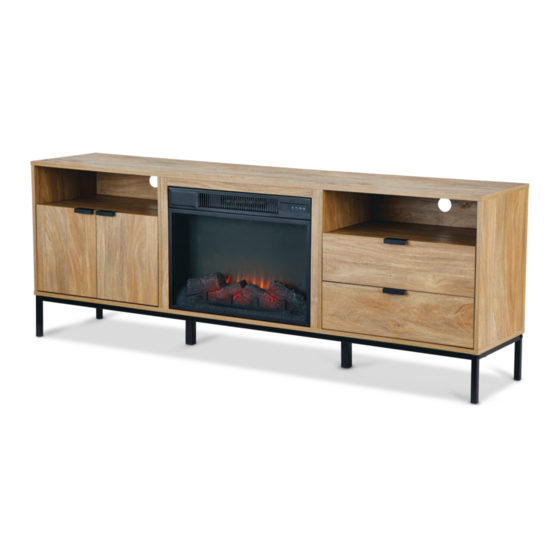
- Page 1 ALMA 72” MEDIA FIREPLACE PRODUCT NO. 064-4023-0 ASSEMBLY INSTRUCTIONS HAVING TROUBLE? TOLL-FREE: 1-888-670-6684 IMPORTANT: Please read this manual carefully before beginning assembly of this product. Keep this manual for future reference.
- Page 2 From on-trend furniture pieces to holiday décor and all your outdoor living essentials, CANVAS™ makes it easy to refresh your space to re ect your unique style and the way you live every day. We would love to hear from you and welcome your thoughtful feedback.
-
Page 3: Table Of Contents
TABLE OF CONTENTS Safety Information Parts List Exploded Parts Hardware List Before You Begin Assembly Step-by-step Guide Instructions for Use Technical Data Troubleshooting Warranty Information WARNING! TO REDUCE THE RISK OF SERIOUS INJURY, READ THE FOLLOWING SAFETY INSTRUCTIONS BEFORE ASSEMBLING AND USING THE PRODUCT. When using electrical appliances, basic precautions should always be followed to reduce the risk of re, electric shock and injury to persons, including the following:... -
Page 4: Safety Information
TOOLS REQUIRED NOTE: Do not overdrill. Be aware of over-drilling. No. 2 Cross-head Screwdriver 2 people Tip Shown Actual Size SAFETY INFORMATION IMPORTANT SAFETY INFORMATION Use this appliance only as described in the manual. Any other use is not recommended by the manufacturer and may cause re, electric shock or injury to persons. - Page 5 9. Use this heater only as described 14. Under no circumstances should this in this manual. Any other use not replace be modi ed. Parts having recommended by the manufacturer to be removed for servicing must may cause re, electrical shock, be replaced prior to operating this or injury to persons.
-
Page 6: Parts List
PARTS LIST ITEM DESCRIPTION THUMBNAIL QUANTITY Top Panel Left Side Panel Right Side Panel Left Partition Panel Right Partition Panel Bottom Panel Centre Shelf Left Door Right Door Middle Crossbar Middle Stile Drawer Face Left Drawer Side ALMA 72” MEDIA FIREPLACE... - Page 7 PARTS LIST ITEM DESCRIPTION THUMBNAIL QUANTITY Right Drawer Side Drawer Back Drawer Bottom Side Back Panel Metal Support Rail Metal Leg Metal Support Leg Drawer Bottom Support ALMA 72” MEDIA FIREPLACE...
-
Page 8: Exploded Parts
EXPLODED PARTS 14x2 15x2 16x2 13x2 21x2 12x2 ALMA 72” MEDIA FIREPLACE... -
Page 9: Hardware List
HARDWARE LIST ITEM DESCRIPTION THUMBNAIL QUANTITY Wood Dowel Larger Cam Bolt Larger Cam Lock Smaller Cam Bolt Smaller Cam Lock Screw Ø3.8x35 mm Screw Ø4x40 mm Screw Ø4x30 mm Extension Slide Extension Rail with Stopper Screw Ø3.5x10 mm Hinge Screw Ø4x12 mm Handle ALMA 72”... - Page 10 HARDWARE LIST ITEM DESCRIPTION THUMBNAIL QUANTITY Screw Ø3.5x12 mm Drawer Connector Screw Ø3.5x12 mm Screw Ø4.7x12.5 mm Anti-Tip Restraint Screw Ø4x20 mm Wall Anchor Washer Bolt: M6x30 mm Back Panel Connector Screw Ø3x16 mm Hex Key Cushioning Cushion Bracket Screw Ø4x10 mm Bracket ALMA 72”...
-
Page 11: Before You Begin Assembly
Place packing materials back in the box. Do not dispose of packaging materials until assembly is complete. READ EACH STEP CAREFULLY Make sure you understand each step. Or if you have any questions, contact CANVAS™ customer service at 1-888-670-6684 (toll-free). ALMA 72” MEDIA FIREPLACE... -
Page 12: Step-By-Step Guide
STEP-BY-STEP GUIDE STEP 1 Insert four Wood Dowels (A) into the designated holes of Centre Shelf (7). Repeat for the other Centre Shelf (7). Securely screw two Cam Bolts (B) and insert four Wood Dowels (A) into the designated holes of Left Side Panel (2). ALMA 72”... - Page 13 STEP-BY-STEP GUIDE STEP 2 Securely screw two Cam Bolts (B) and insert four Wood Dowels (A) into the designated holes of Right Side Panel (3). Separate Extension Slide (I) from Extension Rail with Stopper (J) as shown, then attach Extension Rail with Stopper (J) by using three Screws (K) per Rail. Press locker down to separate the Slide (I) from Rail (J).
- Page 14 STEP-BY-STEP GUIDE STEP 3 Securely screw two Cam Bolts (B) and insert four Wood Dowels (A) into the designated holes of Left Partition Panel (4). Insert two Wood Dowels (A) into the holes of Middle Stile (11). ALMA 72” MEDIA FIREPLACE...
- Page 15 STEP-BY-STEP GUIDE STEP 4 Insert two Wood Dowels (A) into the holes of Middle Stile (11). Securely screw two Cam Bolts (B) and insert four Wood Dowels (A) into the designated holes of Right Partition Panel (5). Separate Extension Slide (I) from Extension Rail with Stopper (J) as shown, then attach Extension Rail with Stopper (J) by using three Screws (K) per Rail.
- Page 16 STEP-BY-STEP GUIDE STEP 5 Attach Middle Stile (11) onto Left Partition Panel (4) by using three Screws (H). Repeat for Right Partition Panel (5). ALMA 72” MEDIA FIREPLACE...
- Page 17 STEP-BY-STEP GUIDE STEP 6 Attach Left Side Panel (2) and Left Partition Panel (4) to Centre Shelf (7) by engaging four Cam Locks (C). Finished edge Unfinished edge Unfinished edge Finished edge ALMA 72” MEDIA FIREPLACE...
- Page 18 STEP-BY-STEP GUIDE STEP 7 Attach Right Side Panel (3) and Right Partition Panel (5) to Centre Shelf (7) by engaging four Cam Locks (C). Finished edge Unfinished edge Unfinished edge Finished edge ALMA 72” MEDIA FIREPLACE...
- Page 19 STEP-BY-STEP GUIDE STEP 8 Align and attach assembly from Step 6 and assembly from Step 7 to Top of Bottom Panel (6) by using eight Screws (G). top of bottom panel ALMA 72” MEDIA FIREPLACE...
- Page 20 STEP-BY-STEP GUIDE STEP 9 Attach Metal Support Rail (18) to Bottom Panel (6) by using five Screws (Q). Repeat for the other Metal Support Rail (18). Attach two Metal Support Legs (20) on Bottom Panel (6) by using four Screws (Q) per Leg. ALMA 72”...
- Page 21 STEP-BY-STEP GUIDE STEP 10 Attach two Metal Legs (19) in place using two Washers (V) and four Bolts (W) per Leg by using provided Hex Key (Z). ALMA 72” MEDIA FIREPLACE...
- Page 22 STEP-BY-STEP GUIDE STEP 11 Insert two Side Back Panels (17) to the slot of Partition Panels, Side Panels and Bottom Panel. ALMA 72” MEDIA FIREPLACE...
- Page 23 STEP-BY-STEP GUIDE STEP 12 Securely screw four Cam Bolts (B) and four Cam Bolts (D) into the designated holes of Top Panel (1). I nsert two Wood Dowels (A) into the designated holes of Middle Crossbar (10). ALMA 72” MEDIA FIREPLACE...
- Page 24 STEP-BY-STEP GUIDE STEP 13 Attach Middle Crossbar (10) on Top Panel (1) by using three Screws (H). ALMA 72” MEDIA FIREPLACE...
- Page 25 STEP-BY-STEP GUIDE STEP 14 Align and attach Top Panel (1) in place by engaging four Cam Locks (C) and four Cam Locks (E). ALMA 72” MEDIA FIREPLACE...
- Page 26 STEP-BY-STEP GUIDE STEP 15 Attach Extension Slide (I) to Left Drawer Side (13) by using three Screws (K). Attach the Drawer Connector (P) in place with two Screws (Q). Repeat for the other Left Drawer Side (13). Attach Extension Slide (I) to Right Drawer Side (14) by using three Screws (K). Attach the Drawer Connector (P) in place with two Screws (Q).
- Page 27 STEP-BY-STEP GUIDE STEP 16 Attach Left Drawer Side (13), Right Drawer Side (14) and Drawer Bottom Support (21) to the Drawer back (15) by using five Screws (F). Repeat to assemble the other drawer. ALMA 72” MEDIA FIREPLACE...
- Page 28 STEP-BY-STEP GUIDE STEP 17 Insert the Drawer Bottom (16) to the slot of Drawer Back and Drawer Sides. Repeat for the other drawer. ALMA 72” MEDIA FIREPLACE...
- Page 29 STEP-BY-STEP GUIDE STEP 18 Securely screw Cam Bolt (D) and attach Handle (N) to the Drawer Face (12) by using two Screws (O). Repeat for the other Drawer Face (12). ALMA 72” MEDIA FIREPLACE...
- Page 30 STEP-BY-STEP GUIDE STEP 19 Align and attach Drawer Face (12) in place by using four Screws (R) and engaging one Cam Lock (E). Repeat for the other Drawer Face (12). ALMA 72” MEDIA FIREPLACE...
- Page 31 STEP-BY-STEP GUIDE STEP 20 Secure the two Hinges (L) in place with two Screws (M) per Hinge. Attach Cushioning Cushion (aa) and Handle (N) to Left Door (8) with two Screws (O). Repeat for Right Door (9). ALMA 72” MEDIA FIREPLACE...
- Page 32 STEP-BY-STEP GUIDE STEP 21 Insert two drawers one by one into your unit, line up the extension slides on the drawer with the extension rails on the unit and push the drawer into the unit until the drawer is fully inserted. The drawer will have to be pushed in all the way initially, to engage the easy slide and soft-close feature.
- Page 33 STEP-BY-STEP GUIDE STEP 22 Install Left Door (8) by fastening the Hinges onto Left Side Panel with four Screws (M) per hinge. Install Right Door (9) by fasten the Hinges onto Left Partition Panel with four Screws (M) per hinge. Adjust the hinges by turning the screws as shown if needed.
- Page 34 STEP-BY-STEP GUIDE STEP 23 Put the insert into place. Secure the insert by using Bracket (xx) and fasten the Bracket to insert by two Screws (yy). Attach the Anti-tip Restraint (S) on top rear of mantel by using Washer (V) and Screw (T). Fasten the Side Back Panels by using Back Panel Connectors (X) and Screws (Y).
- Page 35 ANTI-TIP RESTRAINT STEP 24 Secure the insert by using Brackets (zz) and fasten the Brackets to mantel by six Screws (yy). Drill two holes into the wall and insert Wall Anchors (U). Attach opposite end of the Anti-tip Restraint (S) using Washer (V) and Screw (G) fastened into Wall Anchors. Caution! If installing the mantel on drywall or other hollow wall applications, the Anti-tip Restraint S must be fastened to studs, headers, or other structural wall supports.
- Page 36 ANTI-TIP RESTRAINT WARNING! TO REDUCE THE RISK OF SERIOUS INJURY AND AVOID THE POTENTIAL FOR FURNITURE TIPPING OVER, INSTALL THE ANTI-TIP RESTRAINT HARDWARE. ALMA 72” MEDIA FIREPLACE...
-
Page 37: Instructions For Use
INSTRUCTIONS FOR USE IDENTIFYING THE CONTROL PANEL The control panel is located on the top right corner of the replace/heater unit. The control panel contains the display unit (1), temperature unit indicator (2), main power (3), flame mode (4), heater control (5), and timer function (6). USING THE MAIN POWER BUTTON Press the power button (3) to turn the fireplace/heater unit on and off. - Page 38 INSTRUCTIONS FOR USE USING THE FLAME MODE Press the flame mode (4) to set the Display value Flame effect flames for different flame effects. These Snow white flame levels are shown in the display (1). The flame settings are as shown on the Rubine right.
- Page 39 INSTRUCTIONS FOR USE USING THE TIMER FUNCTION Press the timer function (6) repeatedly to cycle through the following timer settings. These timer interval are shown in the display (1). Display value Timer interval Display value Timer interval 5 hours 30 minutes 6 hours 1 hour 7 hours...
- Page 40 INSTRUCTIONS FOR USE CLOSE OPEN BATTERY SAFETY WARNINGS NOTE: Do not mix old and new batteries. Do not mix alkaline, standard (carbon-zinc), or rechargeable (NiCad, NiMH, etc.) batteries. WARNING: Do not ingest batteries. • Non-rechargeable batteries are not to be recharged. •...
- Page 41 INSTRUCTIONS FOR USE 1. The battery compartment is located on the back of the remote control. 2. Press the small tab inward as you slide the battery door open and remove the exhausted batteries. 3. Insert two new AAA batteries (not included), ensuring the polarities of the batteries match the inside of the battery compartment.
- Page 42 INSTRUCTIONS FOR USE IDENTIFYING THE REMOTE CONTROL The remote control contains the main power (3), flame mode (4), heater control (5), timer function (6), flame brightness (7), heater boost (8) and child safety lock (9). The main power (3), flame mode (4), heater control (5) and timer function (6) on the remote control work in the same way as the buttons on the front panel of the fireplace/heater.
- Page 43 INSTRUCTIONS FOR USE USING THE HEATER BOOST The heater boost (8) is adjustable from the remote control only. To quickly heat up a cold room/space, press the heater boost (8) to run the heater at the full rated wattage. Pressing the heater boost (8) button repeatedly will cycle through the following boost settings.
- Page 44 INSTRUCTIONS FOR USE USING THE CHILD SAFETY LOCK The child safety lock (9) is adjustable from the remote control only. When the unit is ON, hold the child safety lock (9) for 3 seconds to activate the child lock function. “CL” will be shown in the display (1) indicating that the child lock is activated.
-
Page 45: Technical Data
TECHNICAL DATA WARNING! For use with televisions weighing 143 lb 5 oz (65 kg) or less. Use with heavier televisions may cause instability and/or tip over which can be dangerous and cause serious injury. 26 1/2” (67.2 cm) 15 3/8” (39 cm) SPECIFICATIONS 72 x 15 3/8 x 26 1/2”... -
Page 46: Troubleshooting
ASSEMBLY TROUBLESHOOTING HAVING TROUBLE? LET US HELP YOU! TOLL-FREE: 1-888-670-6684 BEFORE RETURNING CALL US, If you have questions regarding your product or require YOUR PRODUCT WE CAN HELP warranty assistance, please call our customer service helpline. PRODUCT TROUBLESHOOTING PROBLEM POSSIBLE CAUSE CORRECTIVE ACTION Display shows “E2”. -
Page 47: Warranty Information
WARRANTY INFORMATION 1-YEAR LIMITED WARRANTY* 1-YEAR LIMITED WARRANTY* This CANVAS product carries a one (1) year warranty against defects in This CANVAS product carries a one (1) year warranty against defects in workmanship and materials. Trileaf Distribution agrees to replace the workmanship and materials. - Page 49 FOYER MULTIMÉDIA DE 72 PO ALMA ARTICLE N 064-4023-0 INSTRUCTIONS D’ASSEMBLAGE VOUS RENCONTREZ DES PROBLÈMES? NUMÉRO SANS FRAIS : 1 888 670-6684 IMPORTANT : Veuillez lire attentivement ce guide avant de procéder à l’assemblage de ce produit. Conservez ce guide aux fins de consultation ultérieure.
- Page 50 C’est pour cela que les collections CANVAS s'inspirent des Canadiens et de leur style de vie. Qu’il s’agisse de meubles tendance, de décorations pour les fêtes ou pour le plein air, CANVAS vous permet de rafraîchir facilement votre espace pour qu’il votre style unique et votre mode de vie.
- Page 51 TABLE DES MATIÈRES Consignes de sécurité Vue éclatée Liste de la quincaillerie Avant de commencer l’assemblage Guide étape par étape Consignes d’utilisation Données techniques Dépannage Renseignements sur la garantie AVERTISSEMENT!VEUILLEZ LIRE LES CONSIGNES DE SÉCURITÉ SUIVANTES AVANT D’ASSEMBLER ET D’UTILISER L’ARTICLE AFIN DE RÉDUIRE LE RISQUE DE BLESSURES GRAVES.
-
Page 52: Consignes De Sécurité
OUTILS REQUIS REMARQUE : Prenez garde à ne pas trop serrer les vis. Tournevis à tête cruciforme n 2 personnes Taille réelle de la tête CONSIGNES DE SÉCURITÉ CONSIGNES DE SÉCURITÉ IMPORTANTES Utilisez cet appareil uniquement comme indiqué dans ce guide. Toute autre utilisation non recommandée par le fabricant peut provoquer un incendie, une décharge électrique ou des blessures corporelles. - Page 53 Utilisez ce foyer uniquement comme décrit Ce foyer ne doit être modifié en aucun cas. dans ce manuel. Toute autre utilisation non Les pièces retirées pour l’entretien doivent recommandée par le fabricant peut causer être replacées avant de pouvoir utiliser le un incendie, un choc électrique ou des foyer à...
- Page 54 LISTE DES PIÈCES RÉFÉRENCE DESCRIPTION ILLUSTRATION QUANTITÉ Panneau supérieur Panneau latéral de gauche Panneau latéral de droite Panneau de partition de gauche Panneau de partition de droite Panneau inférieur Tablette centrale Porte gauche Porte droite Barre transversale moyenne Montant intermédiaire Devanture Côté...
- Page 55 LISTE DES PIÈCES RÉFÉRENCE DESCRIPTION ILLUSTRATION QUANTITÉ Côté droit du tiroir Fond du tiroir Rail de support en métal Patte en métal Patte de soutien en métal Support de fond de tiroir FOYER MULTIMÉDIA DE 72 PO ALMA FOYER MULTIMÉDIA DE 72 PO ALMA...
-
Page 56: Vue Éclatée
VUE ÉCLATÉE 14x2 15x2 16x2 13x2 21x2 12x2 FOYER MULTIMÉDIA DE 72 PO ALMA... -
Page 57: Liste De La Quincaillerie
LISTE DE LA QUINCAILLERIE RÉFÉRENCE DESCRIPTION ILLUSTRATION QUANTITÉ Goujon de bois Grand boulon à came Grande came Petit boulon à came Petite came Rail d’extension avec butée Poignée FOYER MULTIMÉDIA DE 72 PO ALMA... - Page 58 LISTE DE LA QUINCAILLERIE RÉFÉRENCE DESCRIPTION ILLUSTRATION QUANTITÉ Connecteur de tiroir Sangle anti-basculement Cheville d’ancrage Laveuse Tournevis Coussin d’amortissement Support Support FOYER MULTIMÉDIA DE 72 PO ALMA...
-
Page 59: Avant De Commencer L'assemblage
AVANT DE COMMENCER L’ASSEMBLAGE S’ASSURER QUE TOUTES LES PIÈCES SONT COMPRISES vous disposez de tous les outils nécessaires pour l’assemblage. ASSEMBLER DANS UNE ZONE DÉGAGÉE RETIRER LES MATÉRIAUX D’EMBALLAGE Remettez les matériaux d’emballage dans la boîte. Ne les jetez pas avant d’avoir terminé... -
Page 60: Guide Étape Par Étape
GUIDE ÉTAPE PAR ÉTAPE ÉTAPE 1 Insérez quatre goujons de bois (A) dans les trous désignés de la tablette centrale (7). Répétez cette étape pour l’autre tablette centrale (7). Vissez solidement deux boulons à came (B) et insérez quatre goujons de bois (A) dans les trous désignés du panneau latéral de gauche (2). - Page 61 GUIDE ÉTAPE PAR ÉTAPE ÉTAPE 2 Vissez solidement deux boulons à came (B) et insérez quatre goujons de bois (A) dans les trous désignés du panneau latéral de droite (3). Séparez la glissière d’extension (I) du rail d’extension avec la butée (J) comme indiqué, puis fixez le rail d’extension avec la butée (J) au moyen de trois vis (K) par rail.
- Page 62 GUIDE ÉTAPE PAR ÉTAPE ÉTAPE 3 Vissez solidement deux boulons à came (B) et insérez quatre goujons de bois (A) dans les trous désignés du panneau de partition de gauche (4). Insérez deux goujons de bois (A) dans les trous du montant intermédiaire (11).
- Page 63 GUIDE ÉTAPE PAR ÉTAPE ÉTAPE 4 Insérez deux goujons de bois (A) dans les trous du montant intermédiaire (11). Vissez solidement deux boulons à came (B) et insérez quatre goujons de bois (A) dans les trous désignés du panneau de partition de droite (5). Séparez la glissière d’extension (I) du rail d’extension avec la butée (J) comme indiqué, puis fixez le rail d’extension avec la butée (J) au moyen de trois vis (K) par rail.
- Page 64 GUIDE ÉTAPE PAR ÉTAPE ÉTAPE 5 Fixez le montant du milieu (11) sur le panneau de partition de gauche (4) au moyen de trois vis (H). Répétez cette étape pour le panneau de partition de droite (5). FOYER MULTIMÉDIA DE 72 PO ALMA...
- Page 65 GUIDE ÉTAPE PAR ÉTAPE ÉTAPE 6 Fixez le panneau latéral de gauche (2) et le panneau de partition de gauche (4) à la tablette centrale (7) en engageant quatre cames (C). Bord fini Bord non fini Bord non fini Bord fini FOYER MULTIMÉDIA DE 72 PO ALMA...
- Page 66 GUIDE ÉTAPE PAR ÉTAPE ÉTAPE 7 Fixez le panneau latéral de droite (3) et le panneau de partition de droite (5) à la tablette centrale (7) en engageant quatre cames (C). Bord fini Bord non fini Bord non fini Bord fini FOYER MULTIMÉDIA DE 72 PO ALMA...
- Page 67 GUIDE ÉTAPE PAR ÉTAPE ÉTAPE 8 Alignez et fixez l’ensemble de l’étape 6 et l’ensemble de l’étape 7 au panneau inférieur (6) au moyen de huit vis (G). haut du panneau inférieur FOYER MULTIMÉDIA DE 72 PO ALMA...
- Page 68 GUIDE ÉTAPE PAR ÉTAPE ÉTAPE 9 Fixez le rail de support en métal (18) au panneau inférieur (6) au moyen de cinq vis (Q). Répétez cette étape pour l’autre rail de support en métal (18). Fixez deux pattes de support en métal (20) sur le panneau inférieur (6) au moyen quatre vis (Q) par patte.
- Page 69 GUIDE ÉTAPE PAR ÉTAPE ÉTAPE 10 Fixez deux pattes en métal (19) au moyen de deux rondelles (V) et quatre boulons (W) par patte à l’aide de la clé hexagonale fournie (Z). FOYER MULTIMÉDIA DE 72 PO ALMA...
- Page 70 GUIDE ÉTAPE PAR ÉTAPE ÉTAPE 11 Insérez deux panneaux latéraux arrière (17) à la fente des panneaux de partition, des panneaux latéraux et du panneau inférieur. FOYER MULTIMÉDIA DE 72 PO ALMA...
- Page 71 GUIDE ÉTAPE PAR ÉTAPE ÉTAPE 12 Vissez solidement quatre boulons à came (B) et quatre boulons à came (D) dans les trous désignés du panneau supérieur (1). Insérez deux goujons de bois (A) dans les trous désignés de la barre transversale du milieu (10). FOYER MULTIMÉDIA DE 72 PO ALMA...
- Page 72 GUIDE ÉTAPE PAR ÉTAPE ÉTAPE 13 Fixez la barre transversale du milieu (10) sur le panneau supérieur (1) au moyen de trois vis (H). FOYER MULTIMÉDIA DE 72 PO ALMA...
- Page 73 GUIDE ÉTAPE PAR ÉTAPE ÉTAPE 14 Alignez et fixez le panneau supérieur (1) en place en engageant quatre cames (C) et quatre cames (E). FOYER MULTIMÉDIA DE 72 PO ALMA...
- Page 74 GUIDE ÉTAPE PAR ÉTAPE ÉTAPE 15 Fixez la glissière d’extension (I) au côté gauche du tiroir (13) au moyen de trois vis (K). Fixez le connecteur du tiroir (P) en place au moyen de deux vis (Q). Répétez cette étape pour l’autre côté...
- Page 75 GUIDE ÉTAPE PAR ÉTAPE ÉTAPE 16 Fixez le côté gauche du tiroir (13), le côté droit du tiroir (14) et le support inférieur du tiroir (21) au dos du tiroir (15) au moyen de cinq vis (F). Répétez cette étape pour l'autre tiroir. FOYER MULTIMÉDIA DE 72 PO ALMA...
- Page 76 GUIDE ÉTAPE PAR ÉTAPE ÉTAPE 17 Insérez le fond du tiroir (16) à la fente du dos du tiroir et des côtés du tiroir. Répétez cette étape pour l'autre tiroir. FOYER MULTIMÉDIA DE 72 PO ALMA...
- Page 77 GUIDE ÉTAPE PAR ÉTAPE ÉTAPE 18 Vissez solidement le boulon à came (D) et fixez la poignée (N) à la devanture (12) au moyen de deux vis (O). Répétez cette étape pour l’autre devanture (12). FOYER MULTIMÉDIA DE 72 PO ALMA...
- Page 78 GUIDE ÉTAPE PAR ÉTAPE ÉTAPE 19 Alignez et fixez la devanture (12) en place au moyen de quatre vis (R) et en engageant une came (E). Répétez cette étape pour l’autre devanture (12). FOYER MULTIMÉDIA DE 72 PO ALMA...
- Page 79 GUIDE ÉTAPE PAR ÉTAPE ÉTAPE 20 Fixez les deux charnières (L) en place au moyen de deux vis (M) par charnière. Fixez Coussin d’amortissement (aa) et la poignée (N) à la porte de gauche (8) au moyen de deux vis (O). Répétez cette étape pour la porte de droite (9).
- Page 80 GUIDE ÉTAPE PAR ÉTAPE ÉTAPE 21 Insérez les deux tiroirs un par un dans votre meuble, alignez les glissières d’extension situées sur le tiroir avec les rails d’extension situés sur le meuble et poussez le tiroir dans le meuble jusqu’à ce que le tiroir soit complètement inséré. Le tiroir devra être poussé...
- Page 81 GUIDE ÉTAPE PAR ÉTAPE ÉTAPE 22 Installez la porte de gauche (8) en fixant les charnières sur le panneau latéral de gauche au moyen de quatre vis (M) par charnière. Installez la porte de droite (9) en fixant les charnières sur le panneau de partition de gauche au moyen de quatre vis (M) par charnière.
- Page 82 GUIDE ÉTAPE PAR ÉTAPE ÉTAPE 23 Insérez l’appareil dans le foyer. Fixez l’appareil à l’aide du support (xx) et fixez le support à l’appareil au moyen de deux vis (yy). Fixez la sangle anti-basculement (S) en haut à l’arrière du manteau en utilisant la rondelle (V) et la vis (T).
- Page 83 SANGLE ANTI-BASCULEMENT ÉTAPE 24 Fixez l’appareil en utilisant des supports (zz), fixez les supports au manteau au moyen de six vis (yy). Percez deux trous dans le mur et insérez les chevilles d’ancrage (U). Attachez l’extrémité opposée de la sangle anti-basculement (s) au moyen de rondelle (V) et de vis (H) fixées dans les chevilles d’ancrage murales.
- Page 84 SANGLE ANTI-BASCULEMENT AVERTISSEMENT! AFIN DE RÉDUIRE LES RISQUES DE BLESSURES GRAVES ET ÉVITER LE POTENTIEL DE BASCULEMENT DES MEUBLES, INSTALLEZ LES SANGLES ANTI-BASCULEMENT. FOYER MULTIMÉDIA DE 72 PO ALMA...
-
Page 85: Consignes D'utilisation
CONSIGNES D’UTILISATION PANNEAU DE COMMANDE de chauffage. UTILISATION DU BOUTON D’ALIMENTATION Appuyez à nouveau pour éteindre l’appareil. pendant 3 secondes rétablit le réglage d’usine. FOYER MULTIMÉDIA DE 72 PO ALMA... - Page 86 CONSIGNES D’UTILISATION UTILISATION DU MODE FLAMME Valeur Effet de flamme d’affichage pour régler les flammes avec différents Blanc comme neige effets visuels. Ces niveaux d’efet de flamme Rubine des effets de flamme sont indiqués ci-contre. Océan REMARQUE : En mode party, l’appareil Provence effectuera automatiquement un cycle entre Party...
- Page 87 CONSIGNES D’UTILISATION UTILISATION DE LA FONCTION DE MINUTERIE Valeur d’affichage Intervalle de minuterie Valeur d’affichage Intervalle de minuterie 5 heures 30 minutes 6 heures 1 heure 7 heures 2 heures 8 heures 3 heures Aucun ARRÊT 4 heures Le foyer s’éteint automatiquement lorsque la minuterie atteint zéro minute. UTILISATION DE LA TÉLÉCOMMANDE INSTALLATION DES PILES Lors du remplacement des piles, utilisez des piles AAA.
- Page 88 CONSIGNES D’UTILISATION FERMER OUVRIR AVERTISSEMENTS DE SÉCURITÉ CONCERNANT LES PILES REMARQUE : Ne mélangez pas des piles neuves avec des piles usagées. Ne mélangez pas des piles alcalines, standard carbone-zinc ou rechargeables NiCad, NiM , etc. . AVERTISSEMENT : N’avalez pas de piles. •...
- Page 89 CONSIGNES D’UTILISATION 1. Le compartiment à piles est situé à l’arri re de la télécommande. 2. Appuyez sur la petite languette vers l’intérieur tout en ouvrant le couvercle du compartiment à piles et retirez les piles épuisées. 3. Insérez deux nouvelles piles AAA non incluses , en respectant les polarités des piles à...
- Page 90 CONSIGNES D’UTILISATION IDENTIFICATION DE LA TÉLÉCOMMANDE foyer. UTILISATION DE LA LUMINOSITÉ DE LA FLAMME FOYER MULTIMÉDIA DE 72 PO ALMA...
- Page 91 CONSIGNES D’UTILISATION UTILISATION DU BOUTON D’AUGMENTATION DE TEMPÉRATURE DE CHAUFFAGE mande uniquement. sance nominale. Valeur d’affichage Intervalle d’augmentation de température du foyer 5 minutes 10 minutes 15 minutes 20 minutes 25 minutes 30 minutes Aucun ARRÊT FOYER MULTIMÉDIA DE 72 PO ALMA...
- Page 92 CONSIGNES D’UTILISATION UTILISATION DU BOUTON VERROUILLAGE-ENFANT indiquant que le verrouillage-enfant est activé. Tous les boutons sont alors verrouillés. de verrouillage-enfant est activée. Pour désactiver la fonction de verrouillage-enfant, appuyez sur le bouton verrouil- NETTOYAGE ET ENTRETIEN • Assurez-vous que l’appareil est éteint, débranché et que les éléments chauffants sont froids lorsque vous nettoyez le foyer.
-
Page 93: Données Techniques
DONNÉES TECHNIQUES AVERTISSEMENT! Pour une utilisation avec des téléviseurs pesant 143 lb 5 oz L’utilisation avec des téléviseurs plus lourds peut causer de l’instabilité ou des basculements qui peuvent être dangereux et causer des blessures graves. 67,2 cm 39 cm FICHE TECHNIQUE 72 x 1 DIMENSION DE L’ARTICLE (larg. -
Page 94: Dépannage
RÉSOUDRE LES PROBLÈMES DE L’ASSEMBLAGE VOUS RENCONTREZ DES PROBLÈMES? LAISSEZ-NOUS VOUS AIDER! ARRÊT AVANT DE APPELEZ-NOUS, Si vous avez des questions concernant votre produit ou RETOURNER NOUS POUVONS avez besoin d’une assistance au titre de la garantie, VOTRE RÉFÉRENCE VOUS AIDER DÉPANNAGE PROBLÈME CAUSE POSSIBLE... -
Page 95: Renseignements Sur La Garantie
DÉPANNAGE PROBLÈME CAUSE POSSIBLE MESURE CORRECTIVE a. Vérifiez les entrées d’air pour les a. Les entrées d’air sont obstructions ou l’accumulation élevée de sales ou obstruées. Le bruit lorsque le chauffage est activé est b. L’ensemble du foyer est plus fort que la normale. défectueux. - Page 96 D'INSPIRATION CANADIENNE...
Need help?
Do you have a question about the ALMA 064-4023-0 and is the answer not in the manual?
Questions and answers