Table of Contents
Advertisement
Quick Links
INSTALLATION & OPERATION MANUAL
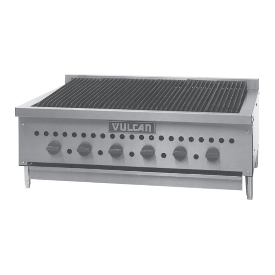
VCCB47
For additional information on Vulcan or to locate an authorized parts and
service provider in your area, visit our website at www.vulcanequipment.com
© ITW Food Equipment Group, LLC
3600 North Point Blvd.
Baltimore, MD 21222
GAS CHARBROILERS
SCB47
MODELS
VCCB25
VCCB36
VCCB47
VCCB60
VCCB72
SCB25
SCB36
SCB47
SCB60
SCB72
RETAIN THIS MANUAL FOR FUTURE USE
FORM F-36952 (9-15)
Advertisement
Table of Contents

Summary of Contents for Vulcan-Hart VCCB25
- Page 1 INSTALLATION & OPERATION MANUAL GAS CHARBROILERS MODELS VCCB25 VCCB36 VCCB47 VCCB60 VCCB72 VCCB47 SCB25 SCB36 SCB47 SCB60 SCB72 SCB47 For additional information on Vulcan or to locate an authorized parts and service provider in your area, visit our website at www.vulcanequipment.com RETAIN THIS MANUAL FOR FUTURE USE ©...
-
Page 2: Important For Your Safety
IMPORTANT FOR YOUR SAFETY THIS MANUAL HAS BEEN PREPARED FOR PERSONNEL QUALIFIED TO INSTALL GAS EQUIPMENT, WHO SHOULD PERFORM THE INITIAL FIELD START-UP AND ADJUSTMENTS OF THE EQUIPMENT COVERED BY THIS MANUAL. POST IN A PROMINENT LOCATION THE INSTRUCTIONS TO BE FOLLOWED IN THE EVENT THE SMELL OF GAS IS DETECTED. -
Page 3: Installation
A grease drawer is provided to collect fat run-off; it opens to the front for inspection or drain -off. Model Number of Burners BTU/hr Input Rating VCCB25, SCB25 58,000 VCCB36, SCB36 87,000 VCCB47, SCB47... -
Page 4: Installation Codes And Standards
LOCATION The installation location must be kept free and clear of combustibles. Do not obst ruct the flow of combustion and ventilation air. DO NOT install the charbroiler adjacent to fryers unless following the provisions detailed by local codes and/or the applicable sections of ANSI-Z223.1/NFPA #54 (latest edition) and NFPA #96 (latest edition) in the United States of America or CAN/CSA 149.1 (latest edition) and CAN/CSA149.2 (latest edition) in Canada. - Page 5 3. NFPA Standard # 96 Vapor Removal from Cooking Equipment , latest edition, available from the National Fire Protection Association, Batterymarch Park, Quincy, MA 02269. In Canada: 1. Local codes. 2. CAN/CSA-B149.1 Natural Gas Installation (latest edition) 3. CAN/CSA-B149.2 Propane Installation Code (latest edition), available from the Canadian Gas Association, 178 Rexdale Blvd., Etobicoke, Ontario, Canada M9W 1R3 BURNERS, RADIANTS, AND TOP GRATES The top grates are shipped flat (top-side down) from the factory.
-
Page 6: Component Parts
COMPONENT PARTS The charbroiler comes with several standard parts as illustrated. Each can be easily removed and installed easily by hand for cleaning and maintenance. Note that the Burner and Deflector are an assembly and are NOT designed to be disassembled. -
Page 7: Gas Pressure Regulator Installation
An adequate gas supply is necessary. Undersized or low pressure lines will restrict the volume of gas required for satisfactory performance. A minimum supply pressure of 7" W.C. for natural gas and 11" W.C. for propane gas is recommended. With all units operating simultaneously, the manifold pressure on all units should not show any appreciable drop. -
Page 8: Operation
CASTER EQUIPPED CHARBROILERS Charbroilers mounted on stands with casters must use a flexible connector (not supplied ) that complies with the Standard for Connectors for Movable Gas Appliances, ANSI Z21.69 • CSA 6.16 and a quick-disconnect device that complies with the Standard for Quick - Disconnect Devices for use W ith Gas Fuel, ANSI -Z21.41 •... -
Page 9: Pilot Adjustment
LIGHTING THE GAS PILOT 1. Turn main gas shut-off valve and the individual burner gas valves OFF. Pilot Wait 5 minutes. 2. Remove the top grates and radiants. Turn the main gas shut-off valve ON. Light pilots using a lit taper. See Fig. 6. Adjust the pilot valve screw until the pilot flame has a slight yellow tip. -
Page 10: Maintenance
CLEANING Scrape top grates during broiling with a wire brush to keep the grates clean. Do not allow debris to accumulate on the grates. Top grates may be immersed in strong commercial cleaning compound overnight. In the morning, rinse with hot water to remove any residues of cleaning compound. -
Page 11: Troubleshooting
TROUBLESHOOTING Uneven heating, sides burning A. Burner valves improperly adjusted B. Fluctuating gas pressure C. Improperly adjusted burner Too much top heat A. Burner valves adjusted too high B. Faulty ventilation C. Overrated gas pressure D. Improperly adjusted bur ner Uneven heat side to side A. - Page 12 PLATE RAIL ACCESSORY INSTALLATION The charbroiler and its parts are hot. Use care when operating, cleaning or servicing the charbroiler. 1. Brackets are reversible – align holes on bottom of plate with slots on the bracket as shown. Attach parts using the included self-tapping screws.
-
Page 13: Back View
SPLASH ACCESSORY INSTALLATION The charbroiler and its parts are hot. Use care when operating, cleaning or servicing the charbroiler. BACK VIEW... - Page 14 WOOD SMOKER BOX ACCESSORY BOTTOM VIEW OF CHARBROILER The charbroiler and its parts are hot. Use care when operating, cleaning or CENTER TRAY GUIDE servicing the charbroiler. WOOD SMOKER BOX INSTALLATION 1. Remove all the radiants and the top grates. 2.
- Page 15 The charbroiler and its parts are hot. Use care when operating, cleaning or servicing the charbroiler. WOOD SMOKER BOX OPERATION 1. The recommended wood log size is 12” long by 4” in diameter and 1-1/2 lb in weight each. Figure. S4 2.
- Page 16 NOTES...


Need help?
Do you have a question about the VCCB25 and is the answer not in the manual?
Questions and answers