
Related Manuals for Alfa Laval Unique Mixproof Horizontal Tank


Summary of Contents for Alfa Laval Unique Mixproof Horizontal Tank
- Page 1 Instruction Manual Unique Mixproof Horizontal Tank Valve - sizes 2½”, 3”, 4” and 6” 2317-0010 ESE02424-EN2 2016-07 Original manual www.sks-online.com www.sks-webshop.com...
- Page 2 www.sks-online.com www.sks-webshop.com...
-
Page 3: Table Of Contents
Table of contents The information herein is correct at the time of issue but may be subject to change without prior notice 1. Declaration of conformity ................2. Introduction .................... 3. Safety ....................3.1. Important information ................3.2. Warning signs ..................3.3. -
Page 4: Declaration Of Conformity
1 Declaration of conformity The Designated Company Alfa Laval Kolding A/S Company Name Albuen 31, DK-6000 Kolding, Denmark Address +45 79 32 22 00 Phone No. hereby declare that Valve Designation Unique HT Type From serial number 1181354 - 9999999... -
Page 5: Introduction
This manual should be considered part of this product and should remain with it at all times for reference. (If you sell it, please be sure to include this manual with it.) Warranty is provided as part of Alfa Laval’s commitment to our customers who operate and maintain their equipment as this manual dictates. -
Page 6: Safety
3 Safety Unsafe practices and other important information are emphasised in this manual. Warnings are emphasised by means of special signs. 3.1 Important information Important information Always read the manual before using the valve! WARNING Indicates that special procedures must be followed to avoid serious personal injury. CAUTION Indicates that special procedures must be followed to avoid damage to the valve. -
Page 7: Safety Precautions
3 Safety Unsafe practices and other important information are emphasised in this manual. Warnings are emphasised by means of special signs. 3.3 Safety precautions Installation: Always read the technical data thoroughly (see chapter 7.1 Technical data) Always release compressed air after use Never touch the clip assembly or the actuator piston rod if the actuator is supplied with compressed air (see warning label) Never stick your fingers through the valve ports if the actuator is supplied with compressed air... -
Page 8: Installation
Fit the warning label supplied on the valve after installation so that it is clearly visible. 4.1 Unpacking/intermediate storage Step 1 CAUTION! Alfa Laval cannot be held responsible for incorrect unpacking. Check the delivery for: 1. Complete valve 2. Delivery note 3. - Page 9 4 Installation The instruction manual is part of the delivery. Study the instructions carefully. Fit the warning label supplied on the valve after installation so that it is clearly visible. Step 5 Inspect the valve for visible transport damage. 2317-0014 Inspection! Step 6 Avoid damaging the air connections, the leakage outlet, the valve...
-
Page 10: Recycling
- At the end of use, the equipment must be recycled according to the relevant, local regulations. Besides the equipment itself, any hazardous residues from the process liquid must be considered and dealt with in a proper manner. When in doubt, or in the absence of local regulations, please contact your local Alfa Laval sales company www.sks-online.com... -
Page 11: General Installation
(see the warning label) CAUTION! - Fit the supplied warning label on the valve so that it is clearly visible. - Alfa Laval cannot be held responsible for incorrect installation NOTE! - The leakage outlet must be turned downwards! Step 2... -
Page 12: Welding
4 Installation Study the instructions carefully and pay special attention to the warnings! The valve has ends for welding as standard. Weld carefully/aim at stressless welding to avoid deformation on sealing areas. Check the valve for smooth operation after welding. 4.4 Welding Step 1 Cutting danger! - Page 13 1. Maintain the minimum clearances "A" so that the actuator with the internal valve parts can be removed - please see later on in this section! If there is a risk of foot damage, Alfa Laval recommends leaving a distance of 120 mm below the valve (look at the specific built-in conditions).
- Page 14 4 Installation Study the instructions carefully and pay special attention to the warnings! The valve has ends for welding as standard. Weld carefully/aim at stressless welding to avoid deformation on sealing areas. Check the valve for smooth operation after welding. Step 5 Pre-use check: 1.
-
Page 15: Operation
- Never touch the clip assembly or the actuator piston rod if the actuator is supplied with compressed air (see the warning label). - Never pressurise air connections (AC1, AC3) simultaneously as both valve plugs can be lifted (can cause mixing). CAUTION! Alfa Laval cannot be held responsible for incorrect operation. Step 2 Burning danger! Never touch the valve or the pipelines when processing hot liquids or when sterilising. -
Page 16: Troubleshooting And Repair
5 Operation Study the maintenance instructions carefully before replacing worn parts. - See “General Maintenance” section 4.1 5.2 Troubleshooting and repair Problem Cause/result Remedy Leakage at the vent port body (106) - Particles between valve seats and plug - Remove the particles seals (56/74) - Check the plug seals - Worn/damaged plug seal rings (56/74) -
Page 17: Recommended Cleaning
5 Operation The valve is designed for cleaning in place (CIP). Study the instructions carefully and pay special attention to the warnings! NaOH = Caustic Soda. = Nitric acid. 5.3 Recommended cleaning Step 1 Caustic danger! Always handle lye and acid with great care. Always use Always use rubber gloves! - Page 18 5 Operation The valve is designed for cleaning in place (CIP). Study the instructions carefully and pay special attention to the warnings! NaOH = Caustic Soda. = Nitric acid. Step 6 Advisory seat lift cleaning periods Cleaning periods of 1-2 seconds per CIP sequence. Product Periods Milk...
-
Page 19: Maintenance
6 Maintenance Maintain the valve/actuator regularly. Study the instructions carefully and pay special attention to the warnings! Always keep spare rubber seals and guide rings in stock. Store seals in closed bag. The items refer to the parts list and service kits section. 6.1 General maintenance Step 1 - Always read the technical data thoroughly (see 7.1 Technical data). - Page 20 - If repair is required, replacing all actuator rubber seals is recommended. - Lubricate seals with Klüberplex BE31. - To avoid possible black marks on pos. 1 and 29, Alfa Laval recommends Klüber Paraliq GTE703 (white) for these two positions.
- Page 21 6 Maintenance Maintain the valve/actuator regularly. Study the instructions carefully and pay special attention to the warnings! Always keep spare rubber seals and guide rings in stock. Store seals in closed bag. The items refer to the parts list and service kits section. Tools required for valve service - 2 x 16 mm Wrench - Strap wrench - 19 mm and 13 mm...
-
Page 22: Dismantling Of Valve (Excluding Actuator)
6 Maintenance Maintain the valve/actuator regularly. Study the instructions carefully and pay special attention to the warnings! Always keep spare rubber seals and guide rings in stock. Store seals in closed bag. The items refer to the parts list and service kits section. 6.2 Dismantling of valve (excluding actuator) Step 1 Remove ThinkTop, if mounted. - Page 23 6 Maintenance Maintain the valve/actuator regularly. Study the instructions carefully and pay special attention to the warnings! Always keep spare rubber seals and guide rings in stock. Store seals in closed bag. The items refer to the parts list and service kits section. Step 5 Remove clamp rings (43).
- Page 24 6 Maintenance Maintain the valve/actuator regularly. Study the instructions carefully and pay special attention to the warnings! Always keep spare rubber seals and guide rings in stock. Store seals in closed bag. The items refer to the parts list and service kits section. Step 8 Remove upper stem (117) by using a 13 mm and a 16 mm wrench.
- Page 25 6 Maintenance Maintain the valve/actuator regularly. Study the instructions carefully and pay special attention to the warnings! Always keep spare rubber seals and guide rings in stock. Store seals in closed bag. The items refer to the parts list and service kits section. Step 11 Sanitise guide ring (109).
-
Page 26: Replacement Of Seal Ring, Tank Plug
6 Maintenance Study the instructions carefully. Handle scrap correctly. 6.3 Replacement of seal ring, tank plug Step 1 Cut and remove old seal ring (74) using a knife, screwdriver or similar. Be careful not to scratch the plug. 2317-0050 Step 2 Pre-mount seal ring as shown on drawing. - Page 27 6 Maintenance Study the instructions carefully. Handle scrap correctly. Step 4 Place lower tool part. 2317-0052 Step 5 Tool marked with item number. 1. Place upper tool part including piston. 2. Clamp the two tool parts together. 2317-0053 Step 6 1.
-
Page 28: Replacement Of Seal Ring, Balanced Plug
6 Maintenance Study the instructions carefully. Handle scrap correctly. 6.4 Replacement of seal ring, balanced plug Step 1 Remove old seal ring (56) using a knife, screwdriver or similar. Be careful not to scratch the plug. 2317-0056 Step 2 Pre-mount seal ring as shown on drawing. 2317-0057 2317-0058 A. - Page 29 6 Maintenance Study the instructions carefully. Handle scrap correctly. Step 4 Place tool part 1. 2317-0059 Step 5 Tooling marked with item number 1. Place tool part 2 including piston. 2. Clamp the two tool parts together. 2317-0060 Step 6 A = on B = off 1.
-
Page 30: Valve Reassembly (Excluding Actuator)
6 Maintenance Study the instructions carefully. Handle scrap correctly. 6.5 Valve reassembly (excluding actuator) Step 1 Assembling valve body sealing element: Lubricate O-rings (108) and lip seal (110). 2317-0063 Step 2 Mount all components in sealing element (107). 2317-0064 www.sks-online.com www.sks-webshop.com... - Page 31 6 Maintenance Study the instructions carefully. Handle scrap correctly. Mounting rotating nozzle (112 + 113) and O-ring (39) on balanced plug: 2317-0065 Step 3 Nozzle and lock ring slides over spindle. 2317-0066 Step 4 Lubricate O-ring (39) and mount O-ring on balanced plug. 2317-0067 www.sks-online.com www.sks-webshop.com...
- Page 32 6 Maintenance Study the instructions carefully. Handle scrap correctly. Mounting valve body sealing element on balanced plug: Step 5 Ensure sealing element is orientated so the white guide ring is upwards. 2317-0069 2317-0068 www.sks-online.com www.sks-webshop.com...
- Page 33 6 Maintenance Study the instructions carefully. Handle scrap correctly. Mounting two-way nozzle (114), spacer (116) and guide rings (115): 2317-0070 Step 6 Insert nozzle, ensure that it is inserted as shown on picture. 2317-0071 Step 7 Insert first guide ring (115). 2317-0072 www.sks-online.com www.sks-webshop.com...
- Page 34 6 Maintenance Study the instructions carefully. Handle scrap correctly. Step 8 Insert spacer (116). 2317-0073 Step 9 Insert last guide ring (115). 2317-0072 Step 10 Insert tank plug (93) from the bottom of balanced plug. 2317-0074 Step 11 Lubricate O-ring (143). Mount O-ring in stem and mount stem for tank plug 2317-0075 www.sks-online.com...
- Page 35 6 Maintenance Study the instructions carefully. Handle scrap correctly. Step 12 Tighten. Use a 13 mm and 16 mm wrench. Torque 20 Nm. 2317-0043 Step 13 Mount O-ring (38). 2317-0076 www.sks-online.com www.sks-webshop.com...
- Page 36 6 Maintenance Study the instructions carefully. Handle scrap correctly. Mounting yoke on actuator: Step 14 Lubricate O-ring (39). 2317-0077 Step 15 1. Mount yoke (15) and the 3 nuts (36) and washers (35). 2. Use a 13 mm wrench. Tighten nuts to 12 Nm. 3.
- Page 37 6 Maintenance Study the instructions carefully. Handle scrap correctly. Assembling vent body sealing element: Step 16 Lubricate O-ring (47) and lip seal (49). 2317-0079 Step 17 Mount all components in sealing elements (105). 2317-0080 www.sks-online.com www.sks-webshop.com...
- Page 38 6 Maintenance Study the instructions carefully. Handle scrap correctly. Assembling valve: Step 18 Lubricate O-rings (40 + 141 + 142). 2317-0081 Step 19 Mount lock ring (44). Mount spindle liner (42) with O-rings (141 + 142) A. Spindle liner can be turned both ways except 6” 2317-0082 www.sks-online.com www.sks-webshop.com...
- Page 39 6 Maintenance Study the instructions carefully. Handle scrap correctly. Step 20 Place sealing element with O-ring and lip seal upwards. 2317-0083 Step 21 1. Mount vent body (106). 2. Mount clamp (64 + 61). 2317-0084 www.sks-online.com www.sks-webshop.com...
- Page 40 6 Maintenance Study the instructions carefully. Handle scrap correctly. Step 22 1. Activate compressed air on lower seat push (yellow air fitting placed on top of actuator). 2. Insert valve plug assembly through vent sealing element. 3. Tighten tank plug by hand. A = tank plug 2317-0085 Step 23...
- Page 41 6 Maintenance Study the instructions carefully. Handle scrap correctly. Step 24 1. Mount flushing pipe (41), tighten with 19 mm wrench. 2. Deactivate lower seat push. 2317-0087 Step 25 Activate compressed air on main stroke. (Blue air fitting placed mid on actuator. 1.
-
Page 42: Dismantling Of Actuator
6 Maintenance Study the instructions carefully. Handle scrap correctly. 6.6 Dismantling of actuator 83/83.1 137 138 2317-0089_1 A = Only for sensor www.sks-online.com www.sks-webshop.com... - Page 43 6 Maintenance Study the instructions carefully. Handle scrap correctly. 1. Remove nuts (36) and washers (35). 2. Pull out intermediate piece (37) from the actuator. 3. Remove cover disk (25). 4. Remove retaining ring (24). 5. Remove piston rod (29), bottom (21) and lower piston (30). 6.
- Page 44 6 Maintenance Study the instructions carefully. Handle scrap correctly. Actuator exploded view 83/83.1 137 138 2317-0089_1 A = Only for sensor www.sks-online.com www.sks-webshop.com...
-
Page 45: Actuator Re-Assembly
6 Maintenance Study the instructions carefully. Handle scrap correctly. 6.7 Actuator re-assembly 1. Fit guide ring (6) and O-ring (5). 2. Fit O-rings (7 and 9). Place upper piston (8). 3. Fit stop (4). 4. Tighten screws (2). 5. Place spring assembly (10). 6. -
Page 46: Technical Data
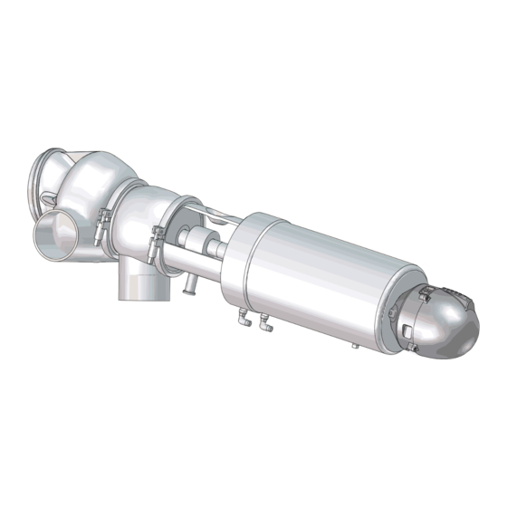
7 Technical data It is important to observe the technical data during installation, operation and maintenance. Inform personnel about the technical data. 7.1 Technical data This Unique Mixproof HT Valve is specially designed for horizontal mounting on the side of a tank or as a space-saving alternative at the bottom of a cone-formed tank. - Page 47 7 Technical data It is important to observe the technical data during installation, operation and maintenance. Inform personnel about the technical data. Weight (kg) 6” 6” Size 2.5” 3” 4” (75 mm) stroke (59 mm) stroke Weight (kg) www.sks-online.com www.sks-webshop.com...
- Page 48 www.sks-online.com www.sks-webshop.com...
-
Page 49: Parts List
8 Parts list 8.1 Wear parts 60/64 60/64 83 83.1 2317-0008_1 = wear parts = sensor kit www.sks-online.com www.sks-webshop.com... - Page 50 8 Parts list Parts list Pos. Denomination O-ring O-ring O-ring O-ring Lip seal Seal ring Seal ring O-ring Lip seal Clamp packing O-ring O-ring O-ring www.sks-online.com www.sks-webshop.com...
-
Page 51: Parts
8 Parts list 8.2 Parts 2317-0009_2 www.sks-online.com www.sks-webshop.com... - Page 52 8 Parts list Parts list Parts list Pos. Denomination Pos. Denomination Lower piston Cpl. Actuator O-ring, NBR Upper stem Screw Guide ring, Turcite Air fitting O-ring, NBR Air fitting Bolt Washer Air fitting 35.1 Washer Stop for upper piston O-ring, NBR Flushing tube Guide ring, Turcite Spindle liner...
-
Page 53: Service Kits
8 Parts list 8.3 Service kits 2317-0006 Service kits www.sks-online.com www.sks-webshop.com... - Page 54 8 Parts list Parts list Service kits Pos. Denomination 2½” + 3” Intermediate piece Service kit, EPDM ........9611926881 Vent body Service kit, NBR .
- Page 55 www.sks-online.com www.sks-webshop.com...
- Page 56 © Alfa Laval Corporate AB This document and its contents is owned by Alfa Laval Corporate AB and protected by laws governing intellectual property and thereto related rights. It is the responsibility of the user of this document to comply with all applicable intellectual property laws. Without limiting any rights related to this document, no part of this document may be copied, reproduced or transmitted in any form or by any means (electronic, mechanical, photocopying, recording, or otherwise), or for any purpose, without the expressed permission of Alfa Laval Corporate AB.
Need help?
Do you have a question about the Unique Mixproof Horizontal Tank and is the answer not in the manual?
Questions and answers