Table of Contents
Advertisement
Quick Links
Advertisement
Table of Contents

Related Manuals for Aqua HC899 Series


Summary of Contents for Aqua HC899 Series
- Page 1 OPERATING AND MAINTENANCE INSTRUCTIONS HC899 HC 899 05/02/2021 Rev.1...
- Page 2 05/02/2021 Rev.1...
-
Page 3: Table Of Contents
ENGLISH 1.0 GENERAL COMMENTS 1.1 Warnings 1.2 Shipping and transporting the pump 1.3 Use of the pump 1.4 Design Standard 2.0 INTRODUCTION 2.1 Programming 3.0 TECHNICAL CHARACTERISTICS 3.1 General rules 3.2 Standard accessories supplied 3.3 Electrical characteristics 3.4 Electrical connections 3.5 Hydraulic connections 3.6 Operations 4.0 MAINTENANCE... -
Page 4: General Comments
GENERAL COMMENTS 1.1 Warnings The aim of HC899 pump manual is to provide you with all the necessary information for a proper installation and maintenance in order to give you optimum results whilst in operation. For this reason it is really important reading with attention the instructions given below since they furnish all the indications necessary for the sureness of the installation, use and maintenance ... -
Page 5: Design Standard
ENGLISH Avoid inverting the pump delivery and suction; Avoid powering the pump with voltages other than those indicated in the technical specifications; Avoid connecting any equipment other than specific equipment to the signal outputs (level, pulse counter, current signal, etc.); 1.4 Design standard Our pumps are built according to the actual general directives endowed with CE mark in conformity with the following European directives:... -
Page 6: Introduction
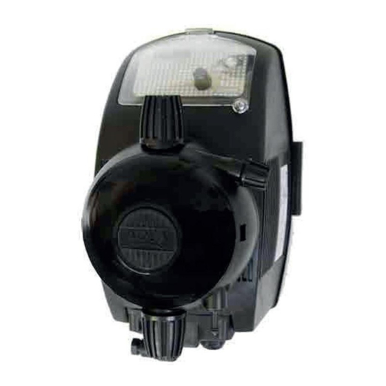
ENGLISH 2.0 INTRODUCTION HC899 are constant flow rate dosing pumps. They are equipped with an ON / OFF switch and a connector for level probe, placed in the bottom of the case. The flow rate can be adjusted from 0 to 100% with a trimmer placed in the front panel of the pump. -
Page 7: Standard Accessories Supplied
ENGLISH 3.2 Standard accessories supplied 1 Foot valve / Strainer. 1 Injection fitting / pressure loading valve. 2 meters opaque PE delivery tubing. 2 meters PVC clear suction tubing. 2 meters PVC clear priming tubing 3.3 Electrical Characteristics Power supply: 230 VAC 50/60 HZ 3.4 Electric connection... -
Page 8: Hydraulic Connections
ENGLISH 3.5 Hydraulic connection After the exact installation of the pump (see generalities), proceed with the connection. Suction: connect the suction tube (PVC soft cristal) to the foot filter that is supplied and put it in the hose clamp, lock the tube closing the nut. If it utilises a level probe, this one has to be connected to the filter through the support that is supplied. -
Page 9: Operations
Connection and exploded views Tubing connections on pump head (Fig. 9) Manual purge (Fig. 10) Low level switch connection (HC899) (Fig. 11) HC899 series exploded view (Fig. 16) HC899 Pump head ball (Fig. 17- Fig. 19) 4.0 MAINTENANCE 4.1 General maintenance comments Regular maintenance is essential if the pump has to give good service over a long period. -
Page 10: Periodic Maintenance
ENGLISH ENGLISH ENGLISH 4.2 Periodic maintenance Liquid’s level in the tank should be monitored regularly and the tank refilled a necessary to avoid the running dry of the pump. Wet parts of the pump, foot valve, suction/delivery valves and the head and diaphragm should be inspected and cleaned at least every 3 months. -
Page 11: Commonly Reported Problems
ENGLISH ENGLISH Valves cleaning HC899 Proceed as follow: 1. With a little tool extract the valve cartridges from their seats 2. Pay attention not to loose the oring at the bottom of the cartridge 3. Clean the valve cartridge with clear water 4. -
Page 12: Chemical Compatibility Table
ENGLISH Chemical Compatibility Table Dosing pumps are widely used for dosing chemical products. It is important to select the most suitable material for the liquid to be dosed. The CHEMICAL COMPATIBILITY TABLE is a precious aid to that end. The following Table must be used as an indicative instrument. Modifications in the transported fluid composition or particular service conditions can reduce the resistance of the materials. -
Page 13: Warranty Certificate
ENGLISH ENGLISH ENGLISH Disclaimer The information included in these tables has been obtained from highly qualified sources which we deem reliable and they are provided without any guarantee, explicit or implicit, concerning their exactness. Conditions or methods for handling, storage and use of the material are beyond our control and/or knowledge. -
Page 14: Dimensions
DIMENSIONI - DIMENSIONS - DIMENSIONS – DIMENSIONES- РАЗМЕРЫ DIMENSIONI - DIMENSIONS - DIMENSIONS – DIMENSIONES - ABME DIMENSIONI - DIMENSIONS - DIMENSIONS - DIMENSIONES Fig. 1 SERIE “HC899” A MURO / WALL MOUNTING / VERSION A PAROI / VERCION A PARED / WANDMONTAGE / НАСТЕННЫЙ... -
Page 15: Connection And Exploded Views
COLLEGAMENTI ED ESPLOSI - CONNECTION AND EXPLODED VIEWS - CONNECTIONS ET EXPLOSE - DIBUJOS - ANSCHLÜSSE UND EXPLOSIONSZEICHNUNGEN - СОЕДИНЕНИЯ И ЧЕРТЕЖИ Fig. 1 COLLEGAMENTI TUBI SUL CORPO POMPA - PUMP HEAD TUBING CONNECTIONS SCHÉMA DE MONTAGE CONNECTIONS EXTERNES - ESQUEMA DE MONTAJE CONNEXIONESTERNAS - SCHLAUCHANSCHLÜSSE AM PUMPENKÖRPER - СОЕДИНЕНИЯ... - Page 16 Fig. 3 HC797-897 COLLEGAMENTO SONDA DI LIVELLO - LOW LEVEL PROBE CONNECTION - SCHÉMA DE MONTAGE SONDE DE NIVEAU - ESQUEMA DE MONTAJE SONDA DE NIVEL – OPTIONAL- ANSCHLUSS DER NIVEAUSONDE - ПОДСОЕДИНЕНИЕ ДАТЧИКА УРОВНЯ – ДОПОЛНИТЕЛЬНАЯ ОПЦИЯ Fig. 4 HC997-999 COLLEGAMENTO SONDA DI LIVELLO - LOW LEVEL PROBE CONNECTION - SCHÉMA DE MONTAGE SONDE DE NIVEAU -...
- Page 17 Fig. 5 SERIE HC 899 - Esploso / Description / Explose / Dibujo/ Explosionszeichnung / ртеж 05/02/2021 Rev.1...
- Page 18 VITE M 5 X 30 UNI 5931 (TCEI) INOX A2 ADSP9300041 COVER IN PP-NERO PER CORPO POMPA HC999 ADSP9000003 TARGHETTA NERA CON LOGO AQUA PER CORPO POMPA 1-14LT HC897 ADSP5007072 OR "R1" NBR - 2.60X1.90 ADSP6000708 VITE M 4 X 8 UNI 7688 (AF-TSTC) INOX A2...
- Page 19 Fig. 8 HC899 - Corpo pompa valvole a labbro e sfera / Pump head lip and ball valves / Corps pompe et clapets à lèvres et bille / Cuerpo de la bomba valvulas a labio y a esfera / Pumpenkörper Lippen- und Kugelventile / Головка насоса, губчатый и шариковый клапан...
- Page 20 15 ADSP9300041 COVER IN PP-NERO PER CORPO POMPA HC999 16 ADSP9000003 TARGHETTA NERA CON LOGO AQUA PER CORPO POMPA 1-14LT HC897 17 ADSP9000019 RONDELLA D. 16 X 0,5 PE NAT ADSP5007200 1A - 2A OR - RIF. 3143 - VITON NERO ADSP5007214 OR - RIF.
- Page 21 Fig. 9 Corpo pompa alte portate / High flowrate Pump head / Corps pompe à débit élevé / Cuerpo de la bomba de alto caudal / Pumpenkopf mit hoher Durchflussrate / Напор насоса с высоким расходом Codice Livello Descrizione componente Quantita' componente necessaria...
- Page 22 Informazioni per la protezione ambientale Ai sensi dell’art. 13 del DL n° 151 del 25/07/2005 (attuazione delle direttive 2011/65/EU , 2002/96/CE,2003/108/CE) si comunica che: I dispositivi elettrici ed elettronici non devono essere considerati rifiuti domestici. I consumatori sono obbligati dalla legge a restituire i dispositivi elettrici ed elettronici alla fine della loro vita utile a degli idonei centri di raccolta differenziata.
- Page 23 HC 899 05/02/2021 Rev.1...
Need help?
Do you have a question about the HC899 Series and is the answer not in the manual?
Questions and answers