Table of Contents
Advertisement
Advertisement
Table of Contents

Related Manuals for Bay Networks BayStack 303

Summary of Contents for Bay Networks BayStack 303
- Page 1 Using the BayStack 303 and 304 Ethernet Switches Part No. 893-01010-A June 1997...
- Page 2 4401 Great America Parkway Santa Clara, CA 95054 © 1997 by Bay Networks, Inc. All rights reserved. Trademarks Bay Networks is a registered trademark of Bay Networks, Inc. BayStack and Bay Networks Press are trademarks of Bay Networks, Inc. Other brand and product names are registered trademarks or trademarks of their respective holders. Statement of Conditions In the interest of improving internal design, operational function, and/or reliability, Bay Networks, Inc.
-
Page 3: En 55 022 Declaration Of Conformance
EN 55 022 Declaration of Conformance This is to certify that the Bay Networks BayStack 303 and 304 Ethernet Switches are shielded against the generation of radio interference in accordance with the application of Council Directive 89/336/EEC, Article 4a. Conformity is declared by the application of EN 55 022 Class A (CISPR 22). - Page 4 893-01010-A...
-
Page 5: Table Of Contents
For More Information ...xvi Safety Messages Safety Alert Message Format ...xvii Safety Alert Messages Used in This Guide ...xix Chapter 1 Introduction to the BayStack 303 and 304 Ethernet Switches Features ...1-1 Physical Description ...1-3 Front Panel ...1-3 10BASE-T Ports ...1-4 10/100BASE-TX Port ...1-5... - Page 6 Installation Requirements ...2-1 Installation Procedure ...2-2 Installing the BayStack Switches on a Flat Surface ...2-2 Installing the BayStack Switch in a Rack ...2-4 Installing a Metal Chassis in a Rack ...2-5 Installing a Plastic Chassis in a Rack ...2-6 Completing Rack Mounting Installation ...2-8 Attaching Devices to the BayStack Switch ...2-9...
- Page 7 Network Management through a Serial I/O Connection ...3-22 Network Management Using a Telnet Connection ...3-22 Upgrading Switch Software Through TFTP Connection ...3-23 Chapter 4 Troubleshooting and Diagnostics BayStack 303 and 304 Switch-related Issues ...4-1 Autonegotiation ...4-2 MDI and MDI-X Connections ...4-3 Installation-related Issues ...4-4 Addresses ...4-5 Cabling ...4-5...
- Page 8 viii 893-01010-A...
- Page 9 Figure 3-2. Menu and screen areas ...3-3 Figure 3-3. BayStack 304 switch as a segment switch ...3-18 Figure 3-4. BayStack 303 as a desktop switch ...3-19 Figure 3-5. Power Up Self Test screen ...3-23 Figure 3-6. Boot Options Menu ...3-24 Figure 3-7.
- Page 10 893-01010-A...
- Page 11 Table 1-1. RJ-45 connector pinout ...1-5 Table 1-2. DB-9 connector pin assignments ...1-7 Table 1-3. Front-panel LEDs ...1-7 Table 1-4. Power and Status LEDs ...1-8 Table 1-5. International power cord specifications ...1-9 Table 2-1. Factory default settings ...2-15 Table B-1. 100BASE-FX MDA LEDs ...
- Page 12 893-01010-A...
-
Page 13: Preface
10BASE-T ports and 100BASE-T ports. Purpose This guide presents information about using the features and capabilities of the BayStack 303 and 304 Ethernet Switches, installing a switch, and configuring the switch through the user interface. Audience This guide is intended for Ethernet administrators with the following background: •... -
Page 14: Conventions
Conventions This section describes the conventions used in this guide. Special Message Formats This guide uses the following formats to highlight special messages: Note: This format is used to highlight information of importance or special interest. Caution: This format is used to highlight information that will help you prevent equipment failure or loss of data. -
Page 15: Ordering Bay Networks Publications
Ordering Bay Networks Publications To purchase additional copies of this document or other Bay Networks publications, order by part number from Bay Networks Press numbers: • Phone—U.S./Canada: 1-888-422-9773 • Phone—International: 1-510-490-4752 • Fax—U.S./Canada and International: 1-510-498-2609 Bay Networks Customer Support You can purchase a support contract from your Bay Networks distributor or authorized reseller, or directly from Bay Networks Services. -
Page 16: For More Information
If you purchased a Bay Networks service program, call one of the following Bay Networks Technical Solutions Centers: Technical Solutions Center Telephone number Billerica, MA Santa Clara, CA Valbonne, France Sydney, Australia Tokyo, Japan For More Information For information about Bay Networks and its products, visit the Bay Networks World Wide Web (WWW) site at http://www.baynetworks.com. -
Page 17: Safety Messages
Traduction des Messages de Sécurité Traducción de los mensajes de seguridad This section translates the safety alert messages used in this guide. Safety alert messages notify users of unsafe actions or conditions that could lead to personal injury or equipment damage. Safety Alert Message Format All safety alert messages are tagged with an international alert symbol. - Page 18 Using the BayStack 303 and 304 Ethernet Switches Symbol Meaning (English, German, French, Spanish, Italian, Japanese) Vorsicht: Dieser Sicherheitshinweis macht den Benutzer auf Maßnahmen oder Bedingungen aufmerksam, die die Verletzung von Personen zur Folge haben können. Achtung: Dieser Sicherheitshinweis macht den Benutzer auf Maßnahmen oder Bedingungen aufmerksam, die eine Beschädigung der Geräte zur Folge...
-
Page 19: Safety Alert Messages Used In This Guide
Safety Alert Messages Used in This Guide The following safety alert message are used throughout this guide. Please read and follow these instructions when you encounter them in the text. Class A Product Copyright page Caution: This device is a Class A product. In a domestic environment, this device can cause radio interference, in which case, the user may be required to take appropriate measures. - Page 20 Accumulated Weight (Shelf or Table Mount) See Caution on page Caution: When this device is installed in a stack on a shelf or tabletop, the accumulated weight of the port cables increases with the height of the shelf or tabletop. Achtung: Wenn dieses Gerät in einem Stapel auf einem Tisch oder einem Regalboden installiert wird, erhöht sich das Gesamtgewicht der Schnittstellenkabel mit der Höhe des Regalbodens oder Tisches.
- Page 21 Stacking Units in a Rack See Caution on page Caution: When mounting this device in a rack, do not stack units directly on top of one another in the rack. Each unit must be secured to the rack with appropriate mounting brackets. Mounting brackets are not designed to support multiple units.
- Page 22 Turning Off Power to the Unit See Warning on page Warning: Removal of the power cord is the only way to turn off power to this device. The power cord must always be connected in a location that can be accessed quickly and safely in case of an emergency.
- Page 23 Reset To Default Settings Command See Caution on page Caution: If you choose the Reset to default settings command, all of your configured settings will be replaced with factory default settings when you press [Enter]. Achtung: Bei Auswahl des Befehls zur Rücksetzung auf die Standardeinstellungen werden alle von Ihnen konfigurierten Einstellungen durch die werkseitigen Standardeinstellungen ersetzt, wenn Sie die Eingabetaste drücken.
-
Page 24: Removing The Top Cover
Removing the Top Cover See Warning on page Warning: To avoid bodily injury from hazardous electrical current, never remove the top cover of the device. There are no user-serviceable components inside. Vorsicht: Um Verletzungsgefahr durch einen elektrischen Stromschlag auszuschließen, nehmen Sie niemals die obere Abdeckung vom Gerät ab. Im Geräteinnern befinden sich keine Komponenten, die vom Benutzer gewartet werden können. -
Page 25: Introduction To The Baystack 303 And 304
• Physical description Features The BayStack 303 and 304 Ethernet Switches are members of the Bay Networks BayStack family of high-performance Ethernet solutions. Both BayStack 303 and 304 switches have built-in management software and power-up diagnostics that allow the switch to begin Ethernet frame switching functions immediately. These BayStack switches provide switch connectivity between 802.3 Ethernet device... - Page 26 Multiple switches can be connected to one another (or to other 802.1D bridges/ switches/hubs) to form a switched/segmented (or bridged) Ethernet backbone. Key features of the BayStack 303 and 304 Ethernet Switches are: • Provides 10 Mb/s and 100 Mb/s switching in the following configurations: —...
-
Page 27: Physical Description
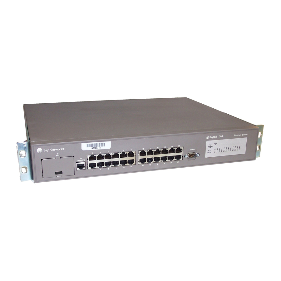
RJ-45 10/100BASE-T port, an expansion slot for the addition of either a 10/ 100BASE-TX or 100BASE-FX port, a DB-9 connector for a console, and assorted LEDs. Figure 1-2 shows the BayStack 303 Ethernet switch. Descriptions of the ports and LEDs follow the figures. 100BASE-TX 1 = One 10/100BASE-TX port... -
Page 28: 10Base-T Ports
10BASE-T Ports The 10BASE-T port connections are provided for the 10 Mb/s Ethernet segment or nodes to attach to the BayStack 303 and 304 Ethernet Switches. The RJ-45 jacks accept standard Category 3, 4, or 5 copper unshielded twisted pair (UTP) cable connections. -
Page 29: 10/100Base-Tx Port
The link status indicator for the 100BASE-TX port is located on the LED panel on the front of the switch. This area also contains a full-duplex (F Dx) status indicator that lights when the port is operating in full-duplex mode. When the port is operating in half-duplex mode, the indicator is off. -
Page 30: Mda Slot
See “Technical Specifications,” for a full description of the MDA. Warning: Power to the switch must be turned off prior to installation of the MDA. Console Port Connector The console port has a DB-9 male connector used to connect a management terminal to the BayStack switch by means of a straight-through DB-9 to DB-9 standard serial port cable. -
Page 31: Leds
Meaning Link is active and connected correctly. Link is inoperative or improperly connected. Switch is receiving valid AC power. Switch is not receiving valid AC power, or internal power supply has failed. Unit is operating properly. Blinking Unit is performing self-tests or network configuration. -
Page 32: Power Cord Specifications
Half/full-duplex * F Dx Green * Indicator applies to 10/100BASE-TX port only (port 13 on BayStack 304 and port 25 on BayStack 303). The unit AC power supply status LED and the system status LED work together to provide status information. - Page 33 Table 1-5 lists specifications for international power cords. Table 1-5. Country/Plug description Continental Europe: • CEE7 standard VII male plug • Harmonized cord (HAR marking on the outside of the cord jacket to comply with the CENELEC Harmonized Document HD-21) U.S./Canada/Japan: •...
-
Page 35: Installing The Baystack Switches
Chapter 3, “Customizing and Managing the BayStack further configure your BayStack switches. Installation Requirements Before installing a The BayStack 303 or 304 switch, verify that the package contains the following items in addition to this guide: • A BayStack 303 Ethernet Switch or BayStack 304 Ethernet Switch •... -
Page 36: Installation Procedure
The BayStack switches can be mounted onto any appropriate flat surface that can safely support the weight of a switch and its attached cables, as long as there is adequate space around the unit for ventilation and access to cable connectors. -
Page 37: Installing The Baystack Switch In A Rack
The brackets for both the metal and plastic chassis can be installed at various positions along the side of the switch to position it in the rack. Determine how far you want the switch to protrude from the rack (see 893-01010-A Switch”... -
Page 38: Installing A Metal Chassis In A Rack
Figure 2-1. Installing a Metal Chassis in a Rack To install the metal switch chassis in a 19-inch rack, you need to determine the exact location and position of the switch in the rack. The mounting brackets shipped with the metal chassis allow the positioning of the switch to be adjusted to accommodate your needs. -
Page 39: Installing A Plastic Chassis In A Rack
The plastic chassis requires different rack mounting brackets. The plastic chassis rack mounting brackets use slots in the sides of the chassis. Determine which position you want for the switch in the rack and select the appropriate slots (see Figure 2-1... - Page 40 There are three slots located on the side of the chassis. To install the switch flush with the rack, use the front and middle slots. To install the switch extended out from the rack, use the middle and back slots.
-
Page 41: Completing Rack Mounting Installation
Completing Rack Mounting Installation Once the switch is secured to the rack, connect the devices and apply power using the following steps: Attach all devices to the ports. “Attaching Devices to the BayStack Attach the power cord to the back of the switch. -
Page 42: Attaching Devices To The Baystack Switch
Attaching Devices to the BayStack Switch After you have installed the BayStack 303 or 304 switch, you can connect it to any equipment that conforms to the IEEE 802.3 standard, such as the following devices: • Ethernet networking devices •... -
Page 43: Connecting The 10/100Base-Tx Port
Connecting the 10/100BASE-TX Port Both BayStack 303 and 304 switches contain an onboard 10/100 Mb/s port that uses autonegotiation with the connecting device to determine the wire speed. An optional second 10/100 Mb/s port can be added by installing the 10/100BASE-TX MDA. - Page 44 All the high-speed ports on the BayStack 303 and 304 switches support full-duplex. For more information on autonegotiation, see “Autonegotiation” on page 4-2.
-
Page 45: Connecting The 100Base-Fx Port
The serial console interface is an RS-232 port that enables a connection to a PC or terminal for monitoring and configuring the switch. You can also connect this port to an external modem to enable remote dial-in management of the switch. The port is implemented as a data communication equipment (DCE) connection, using a male DB-9 connector. - Page 46 Connect the terminal (or a computer in terminal-emulation mode) to the console port using the RS-232 cable. Connect the female connector of the RS-232 cable directly to the service port on the switch, and tighten the captive retaining screws (see 2-12 Connector”...
-
Page 47: Power-Up Self-Tests
Turn on the terminal. If the switch power is already turned on, press [Esc] to display the Main Menu. You can now access the configuration menus to observe self-tests and to modify operating parameters for the switch. - Page 48 If you have a terminal or console connected to the switch, the Main Menu is displayed unless it is the initial power-up sequence of the switch or a Reset to Defaults was performed. In the latter two cases, the switch displays the...
-
Page 49: Initial Setup Of A Baystack Ethernet Switch
Initial Setup of a BayStack Ethernet Switch In most cases, the BayStack 303 and 304 Ethernet Switches can be installed and made operational using the system default settings. Minimal configuration is required when you plan on remote management or TFTP operations. -
Page 50: Selecting A Language
IP Address (1, 2, 3, & 4) Selecting a Language The BayStack 303 and 304 switches are designed to interface with the user in one of seven languages. Selection of a user interface language is done from the language menu, shown in initial power-up sequence and whenever the system is reset to default values. -
Page 51: Installing The Baystack Switches
1 -- System Information 2 -- System Configuration 3 -- Reset System 4 -- Exit Telnet Enter Command ([ESC]---Previous Screen [Space]---Refresh Screen) Figure 2-9. 893-01010-A Figure 2-9). Bay Networks BayStack 303 Ethernet Switch [0.0.0.0] [00:00:81:12:12:12] [1.0] [0d:00h:00m:00s] [Switching] Main Menu Main Menu 2-17... - Page 52 To set the IP address, subnet mask, and gateway address for the switch, follow these steps: Type 2 to select 2---System Configuration from the Main Menu. This selection displays the System Configuration menu (see ***************************************************************************** IP Address: Mac Address: Software Version:...
- Page 53 32-bit Internet address. This notation is called dotted-decimal notation. The largest possible value of a field in a dotted-decimal number is 255, which represents an octet of all ones. 893-01010-A Bay Networks BayStack 303 Ethernet Switch [0.0.0.0] [00:00:81:12:12:12] [1.0] [0d:00h:00m:00s]...
- Page 54 This action refreshes the screen and displays the new value in the field on the menu. Type 1 at the System Configuration menu. The Switch Network Configuration menu is displayed (see From this menu, the IP address and Telnet password can be set. 2-20 Figure 2-11).
-
Page 55: Customizing And Managing The Baystack Switches
Using the Menus and Screens The agent software on the BayStack 303 and 304 switches provides menus and screens that allow you to configure and manage your network environment. A menu provides the ability to set and change parameters, and a screen presents current status and parameter settings. - Page 56 2 --- Spanning Tree Information 3 --- Port Statistics and Status Information 2 --- System Configuration 1 --- Switch Network Configuration 2 --- High Speed Port Configuration 3 --- Spanning Tree Configuration 4 --- SNMP Configuration 5 --- Reset to Default...
-
Page 57: Menu And Screen Areas
Menu and Screen Areas The menus and screens of the switch software are partitioned into the following three distinct areas, as shown in • Switch status area • Central screen area—menu commands and status • Navigation commands and command line area •••••••••••••••••••••••••••••••••••••••••••••••••••••••••••••••••••••••... -
Page 58: Switch Status Area
Switch Status Area The switch status area appears in the top portion of each menu and screen. This area contains the information necessary to identify the BayStack switch and see its current status. The switch status area provides the following information: •... -
Page 59: Menu And Screen Descriptions
Menu and Screen Descriptions The BayStack 303 and 304 switch console interface consists of menu and screen displays that allow you to manage the switch and monitor its performance. Menus are provided to allow selection of switch parameters and a means to change and manipulate them. -
Page 60: Language Selection Menu
The Language selection menu lists the seven languages in which you can display the BayStack user interface. This menu is displayed at the initial power-up sequence of the switch (when the switch is first turned on). Subsequent power-up procedures display the Main Menu. After you select a language, this menu is displayed only if you press Esc from the Main Menu. -
Page 61: System Information
System Information The System Information screen displays the current parameter settings for the switch. All of the screens associated with system information are read only. To change any parameter or setting you must go through the System Configuration menu. The System Information screen provides three paths to switch statistics and status information. - Page 62 This field allows you to define how many seconds elapse between hello time messages that are sent from this switch to all other switches, if the Spanning Tree Protocol has defined this switch as the root switch. This field is configurable in the range of 1 to 65535 seconds with a default of 2 seconds.
- Page 63 Provides the time since the last topology change was detected by the bridge entity. • Root Cost Provides the path cost from the switch to the designated root bridge. • Hold Time Specifies the time value that determines the interval length during which no more than two configuration bridge PDUs shall be transmitted by this node.
- Page 64 This information provides the path cost to the designated root bridge. The valid range for this value is from 1 to 65,535. Entering a value of 0 causes the switch software to compute the value automatically. The default value for this field is 0.
- Page 65 • Rx CRC Error Frame This counter increments whenever a frame is received on a particular interface that is an integral number of octets in length but does not pass the frame check sequence (FCS). • Rx Frame Too Long This counter increments whenever a frame is received on this port that is greater than 1,518 octets in length.
-
Page 66: System Configuration
Port Status Information screen. System Configuration The System Configuration menu provides the means to change parameter settings within specific areas of the switch network. This menu contains the following selections: 1---Switch Network Configuration 2---Port Configuration... - Page 67 When multiple paths exist, the spanning tree algorithm configures the network so that a bridge/switch uses only the most efficient path. If that path fails, the protocol automatically reconfigures the network to make another path become active, sustaining network operations.
-
Page 68: Port Configuration
The Port Configuration menu allows the user to define the functions of the high-speed ports. On the BayStack 303 switch, this menu addresses ports 25 and 26. On a BayStack 304 switch, this menu addresses ports 13 and 14. Options provided on the Port Configuration menu are:... - Page 69 This field allows you to define how many seconds elapse between hello time messages that are sent from this switch to all other switches, if the Spanning Tree Protocol has defined this switch as the root switch. This field is configurable in the range of 1 to 65535 seconds with a default of 2 seconds.
-
Page 70: Snmp Configuration
SNMP Configuration The SNMP Configuration menu displays a list of the parameters that allow you to set and change values, parameters, and addresses within an SNMP management environment. To change any setting, type in the corresponding number. The screen is refreshed, and the command line displays the current parameter value for the selected parameter and allows you to enter new data. -
Page 71: Reset To Default
• Management using SNMP Configuration Examples The BayStack 303 and 304 switches are well suited for the initial migration from shared 10BASE-T segments to dedicated bandwidth for switch connections between segments, end-stations, 100BASE-T Fast Ethernet servers, and fiber or copper Fast Ethernet backbone connections. The switches also function well as segment or desktop switches. - Page 72 BayStack 304 switch as a segment switch Figure 3-3 illustrates how a BayStack 304 switch can be used as a segment switch to alleviate server and network center contention and to provide better ratio connections to 10 Mb/s users. This configuration also offers an additional eight dedicated 10 Mb/s connections for users.
-
Page 73: Spanning Tree Protocol
The BayStack 303 switch can be used as a desktop switch to provide 100 Mb/s connections to the server and network center and to give dedicated 10 Mb/s connections to up to 23 users instead of shared 10 Mb/s connections (see Figure 3-4). -
Page 74: Managing The Baystack Switches
Managing the BayStack Switches You can manage your BayStack 303 and 304 switches in any of the following three ways: • In-band signaling using SNMP (see page •... - Page 75 Access to the switch through SNMP is controlled by community names. The community names set for the switch must match those used by the SNMP management station for successful communication to occur. The switch uses two community names.
-
Page 76: Network Management Through A Serial I/O Connection
Network Management through a Serial I/O Connection Each BayStack 303 and 304 switch can be managed using a PC or terminal connected to the switch through the RS-232 console port located on the front of the switch. The serial connection allows the network manager to view statistics and change parameter settings using the built-in user interface. -
Page 77: Upgrading Switch Software Through Tftp Connection
Type 3 to select Reset System from the Main Menu. The Reset System selection performs a soft reset of the switch and runs power-up diagnostics. During this time, the Power Up Self Test screen is... -
Page 78: Boot Options Menu
Pressing Return causes the power-up self-tests to be interrupted and displays the Boot Options Menu (see *************************************************************************** MAC Address: 00.00.00.00.00.00 *************************************************************************** 1---Upgrade Switch Software 2---Boot Switch Software Enter Command: [2] Figure 3-6. 3-24 Figure 3-6). Bay Networks BayStack 30X Ethernet Switch Boot Options Menu Boot Options Menu 893-01010-A... - Page 79 Enter all the necessary information (options 1 through 5) by typing the command number and entering the information at the command line. Type 6 to download the software to the flash memory of the switch. The software is downloaded from the TFTP server to the flash memory of the BayStack switch.
-
Page 81: Troubleshooting And Diagnostics
The BayStack 303 and 304 Ethernet Switches are designed to be as simple and reliable as possible. Occasionally, problems may arise that are largely associated with two areas: problems related to the BayStack switches and problems related to the installation. -
Page 82: Autonegotiation
(see Configuration” on When the link is first brought up, the BayStack 303 and 304 switches sense the speed of the connecting device. If the connecting device changes speed without performing a link down, the BayStack switch can correctly sense a change from 100 Mb/s to 10 Mb/s;... -
Page 83: Mdi And Mdi-X Connections
MDI-X ports (where “X” refers to the crossover function). Note: For the transmitter of one device to connect to the receiver of another device, the sum of crossovers must always be an odd number. BayStack 303/304 switch MDI-X port Figure 4-1. MDI-X to MDI cable connections... -
Page 84: Installation-Related Issues
If you are connecting a device to the BayStack switches that also implements MDI-X ports (see BayStack 303/304 switch MDI-X port Figure 4-2. MDI-X to MDI-X cable connections Installation-related Issues Ethernet 10BASE-T networks tend to be fairly simple, but they can still have problems that take time to resolve. -
Page 85: Addresses
Remember that the BayStack switches each have a MAC station address and an IP address. The MAC station addresses are unique because each address contains the Bay Networks manufacturer ID and node ID codes. The switch is shipped with a default IP address of 000.000.000.000. -
Page 86: Link Status
The 100 Mb/s ports are designed to operate using Category 5 UTP cabling only. Category 5 UTP cable is a 2-pair cable certified to handle up to 100 MHz bandwidth. To minimize crosstalk noise, maintain the twist ratio of the cable up to the point of termination (untwist at any termination should not exceed 0.5 inches). -
Page 87: Technical Specifications
General Specifications Network Protocol Standards Supported Data rate BayStack 303 switch: BayStack 304 switch: Electrical Specifications Input current: Input voltage (rms): Power consumption: Environmental Specifications Operating temperature: Storage temperature: Operating humidity: Storage humidity: Operating altitude: 893-01010-A Appendix A Technical Specifications... - Page 88 Electromagnetic Emissions Safety Agency Approvals 1.5 in. (3.85 cm) 5.8 in. (14.90 cm) 4.25 in. (10.90 cm) BayStack 303: 350 K BayStack 304: 280 K Packets per second, maximum—learned unicast traffic For 10 Mb/s: 14,880 packets per second max For 100 Mb/s: 148,810 packets per second...
-
Page 89: Declaration Of Conformity
Declaration of Conformity The following Declaration of Conformity for the BayStack 303 and 304 Ethernet Switches complies with ISO/IEC Guide 22 and EN 45014. The declaration identifies the product, the Bay Networks name and address, and the applicable specifications that are recognized in the European community. -
Page 91: Media Dependent Adapters (Mdas)
The BayStack 303 and 304 Ethernet Switches come with an optional 100 Mb/s port. To use this port, a media dependent adapter (MDA) is inserted in the switch through the front panel. The media adapter slot accepts either a 100BASE-TX (UTP) or 100BASE-FX (fiber) media adapter to provide a switched Fast Ethernet link to high-speed... - Page 92 MFX-1 100BASE-FX 1 = Status indicators Link–valid communication link established F Dx–port operating in full-duplex mode (LED lit) or half-duplex mode (LED off) 2 = 100BASE-FX SC port connector Figure B-1. The 100BASE-FX MDA has its own LED indicators, described in Table B-1.
-
Page 93: 10/100Base-Tx Mda
10/100BASE-TX MDA The optional expansion slot can be used for a 10/100BASE-TX MDA that supports autonegotiation for either 10 Mb/s or 100 Mb/s operation, depending on the connecting device. For more information about autonegotiation, see “Connecting the 10/100BASE-TX The MDA, shown in LEDs. -
Page 94: Installing An Mda
F Dx Green Installing an MDA The expansion slot on the BayStack 303 or 304 switch accommodates a small media dependent adapter that provides one high-speed port connection. The connection can be either an RJ-45 10/100BASE-TX MDA or a fiber 100BASE-FX MDA with an SC connector. - Page 95 Insert the MDA into the slot, taking care to slide the MDA onto the guides “see Figure The guides ensure that the MDA connector plugs correctly into the switch motherboard. The guides are part of the plastic and metal chassis. Caution: Make sure the MDA slides in on the guides. Failure to align the guides could result in bent and broken pins.
- Page 97 , 1-5, 2-11, 4-2 autonegotiation , xv Bay Networks Press , xvi Bay Networks World Wide Web page , 1-3 BayStack 303 switch front panel , 1-4 BayStack 304 switch front panel , 3-24 Boot Options menu Bridge , 3-10...
- Page 98 , 2-15 default settings , 3-11 deferred transmissions , 3-8 Designated Root , 3-19 desktop switch , 2-9 devices, attaching to the switch , 4-1 diagnostics , 2-11 duplex indicator , A-1 electrical specifications , A-2 electromagnetic specifications , A-1 environmental specifications...
- Page 99 , 1-2 MAC address support , 2-17, 3-6 Main Menu management information base. managing the switch , 3-22 through serial I/O , 3-22 using a Telnet connection , 3-20 using SNMP , 3-8 Max Age Time , B-3 10/100BASE-TX , B-1...
- Page 100 , 1-7 Status LED , 2-20 subnet mask switch autonegotiation configuration configuration examples desktop switch, used as , 2-17 initial setup , 3-20 managing , 3-10 rack mounting segment switch, used as , 2-3 stacking...
- Page 101 , xv, xvi Technical Solutions Centers , A-1 technical specifications Telnet , 3-22 interface , 3-13 password , 3-13 Telnet Access field , 2-12 terminal requirements , 3-23 TFTP, initiating a session , 1-2 throughput, aggregate , 3-9 time since topology change , 3-9 topology change Trap Receiver # Community Name and IP Address...
Need help?
Do you have a question about the BayStack 303 and is the answer not in the manual?
Questions and answers