Table of Contents
Advertisement
Use
CC1N7435en
11.01.2007
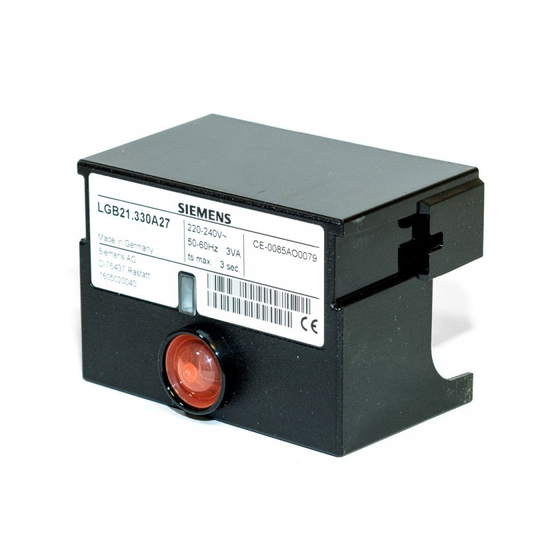
Burner Controls
Burner controls for the supervision of 1- or 2-stage gas or gas / oil burners of
small to medium capacity (typically up to 350 kW), with or without fan, in intermit-
tent operation.
The LGB... and this Data Sheet are intended for use by OEMs which integrate the
burner controls in their products!
The LGB... burner controls are used for the startup and supervision of 1- or 2-stage gas
or gas / oil burners in intermittent operation.
Depending on the type of burner control used, the flame is supervised either by an
ionization probe, a blue-flame detector QRC1... for forced draft gas / oil burners, or a
Uv Detector Qra... (with auxiliary unit AGQ1...A27).
In connection with the respective adapters, the LGB... burner controls replace their
predecessor types LFI7... and LFM1... (also refer to «Replacement types» under «Or-
dering»).
Automatic forced draft burners for gaseous fuels to EN 676
-
Gas burner controls to EN 298
-
Undervoltage detection
-
Air pressure supervision with function check of the air pressure switch during
-
startup and operation
Electrical remote reset facility
-
LGB41... for use with atmospheric gas burners
-
7
LGB...
Building Technologies
HVAC Products
435
Advertisement
Table of Contents


Need help?
Do you have a question about the LGB21.130A17 and is the answer not in the manual?
Questions and answers