Cambium Networks PTP 820C Installation Manual
System release 10.0
Hide thumbs
Also See for PTP 820C:
- User manual (672 pages) ,
- Quick start manual (23 pages) ,
- Installation instructions (3 pages)
Table of Contents
Advertisement
Quick Links
Advertisement
Table of Contents

Related Manuals for Cambium Networks PTP 820C


Summary of Contents for Cambium Networks PTP 820C
- Page 1 INSTALLATION GUIDE PTP 820C and PTP 820C Assured System Release 10.0...
- Page 2 Accuracy While reasonable efforts have been made to assure the accuracy of this document, Cambium Networks assumes no liability resulting from any inaccuracies or omissions in this document, or from use of the information obtained herein. Cambium reserves the right to make changes to any products described...
-
Page 3: Table Of Contents
Inspection ............................. 1-6 PTP 820 Assured Platform ......................... 1-7 Chapter 2: Product Hardware Description ..................2-1 PTP 820C Hardware Overview ......................2-2 PTP 820C Interfaces ........................2-3 MultiCore Mediation Devices (MCMD) .................... 2-4 PoE Injector ............................2-6 PoE Injector Interfaces ........................ 2-6 System Components ......................... - Page 4 Preparing the Ethernet Cable and Plug-in Field ..............3-30 Preparing the Ethernet Cable Already Assembled ..............3-34 Connection of Ethernet Cable to PTP 820C ................3-35 Management Connection for 4x4 MIMO and 1+1/2+2 HSB Configurations ....... 3-37 Preparing a MIMO/Protection Signaling Cable ..............3-37 Connecting the MIMO/Protection Splitters and Protection Signaling Cable .......
- Page 5 Chapter 5: Generic Installation Procedures ................... 5-1 General Notes Concerning All Installation Procedures ..............5-2 Torque Requirements ........................5-3 PTP 820C DC Pole Mount Procedure ....................5-4 List of Items ..........................5-4 Required Tools ..........................5-4 Installation Procedure ......................... 5-4 6-13 GHz Installation Procedure ....................
- Page 6 Contents List of Items ..........................6-19 Required Tools .......................... 6-19 Insertion Loss ..........................6-20 Procedure ........................... 6-20 MultiCore 2+2 HSB Double Polarization Remote Mount .............. 6-23 List of Items ..........................6-23 Required Tools .......................... 6-23 Insertion Loss ..........................6-24 Common Installation ......................... 6-24 6-13 GHz .............................
- Page 7 Contents Procedure ........................... 6-58 2x2 LoS MIMO Remote Mount ....................... 6-62 List of Items ..........................6-62 Required Tools .......................... 6-62 Insertion Loss ..........................6-62 6-13 GHz ............................. 6-63 15-38 GHz ........................... 6-65 4x4 LoS MIMO Direct Mount......................6-67 List of Items ..........................6-67 Required Tools ..........................
- Page 8 Contents Scope ............................8-9 Commissioning Test ........................8-9 PTP 820 Commissioning Log ......................8-11 phn-3962 004v000 Page vi...
- Page 9 Contents List of Figures Figure 1 PTP 820C Rear View (Left) and Front View (Right) ..............2-2 Figure 2 Cable Gland Construction ......................2-2 Figure 3 PTP 820C Interfaces ........................2-3 Figure 4 Splitter ............................2-4 Figure 5 OMT ............................2-5 Figure 6 PoE Injector ..........................
- Page 10 Contents List of Tables Table 1 MCMD type ..........................2-4 Table 2 Adaptors and Installation kits for 6 to 18 GHz ............... 2-10 Table 3 Adaptors and Installation kits for 23 to 38 GHz ..............2-10 Table 4 Remote Mount – 6 to 15 GHz ....................2-11 Table 5 Remote Mount –...
- Page 11 Contents Table 42 Required items for MultiCore 2+0 HSB Dual Polarization Remote Mount ....... 6-47 Table 43 Insertion loss for MultiCore 2+0 Dual Polarization Remote Mount ........6-48 Table 44 Required items for 2 x MultiCore 2+0 Single Polarization Direct Mount ......6-54 Table 45 Insertion loss for 2 x MultiCore 2+0 Single Polarization Direct Mount ......
-
Page 12: About This Installation Guide
About This Installation Guide This guide describes the PTP 820C installation procedures and provides additional information concerning system parts and frequency bands. This guide contains the following chapters: • Chapter 1 : Before You Start • Chapter 2 : Product Hardware Description •... -
Page 13: Purpose
It is recommended that all personnel engaged in such activities be properly trained. Cambium Networks disclaims all liability whatsoever, implied or express, for any risk of damage, loss or reduction in system performance arising directly or indirectly out of the failure of the customer, or anyone acting on the customer's behalf, to abide by the instructions, system parameters, or recommendations made in this document. -
Page 14: Problems And Warranty
Hardware warranty Cambium Networks’s standard hardware warranty is for one (1) year from date of shipment from Cambium Networks or a Cambium distributor. Cambium Networks warrants that hardware will conform to the relevant published specifications and will be free from material defects in material and workmanship under normal use and service. -
Page 15: Security Advice
Security advice Security advice Cambium Networks systems and equipment provide security parameters that can be configured by the operator based on their particular operating environment. Cambium recommends setting and using these parameters following industry recognized security practices. Security aspects to be considered are protecting the confidentiality, integrity, and availability of information and assets. -
Page 16: Warnings, Cautions, And Notes
Warnings, cautions, and notes Warnings, cautions, and notes The following describes how warnings and cautions are used in this document and in all documents of the Cambium Networks document set. Warnings Warnings precede instructions that contain potentially hazardous situations. Warnings are used to alert the reader to possible hazards that could cause loss of life or physical injury. -
Page 17: Caring For The Environment
Networks equipment in EU countries. Disposal of Cambium Networks equipment European Union (EU) Directive 2002/96/EC Waste Electrical and Electronic Equipment (WEEE) Do not dispose of Cambium Networks equipment in landfill sites. For disposal instructions, refer to http://www.cambiumnetworks.com/support/weee-compliance Disposal of surplus packaging Do not dispose of surplus packaging in landfill sites. -
Page 18: Chapter 1: Before You Start
Cambium Networks PTP 820C represents a new generation of radio technology, capable of high bit rates and longer reach and suitable for diverse deployment scenarios. PTP 820C is a MultiCore system that utilizes parallel radio signal processing in a compact, all- outdoor device combining radio, baseband, and Carrier Ethernet functionality to offer a future proof solution for PTP connectivity applications. -
Page 19: Important Notes
• PTP 820C is intended for installation in a restricted access location. • PTP 820C must be installed and permanently connected to protective earth by qualified service personnel in accordance with applicable national electrical codes. phn-3962 004v000 Page 1-2... -
Page 20: Safety Precautions & Declared Material
Use of controls, adjustments, or performing procedures other than those specified herein, may result in hazardous radiation exposure. Caution When working with a PTP 820C, note the following risk of electric shock and energy hazard: Disconnecting one power supply disconnects only one power supply module. To isolate the unit completely, disconnect all power supplies. - Page 21 Caution L’usage de PTP 820C s’accompagne du risque suivant d'électrocution et de danger électrique : le débranchement d'une alimentation électrique ne déconnecte qu'un module d'alimentation électrique. Pour isoler complètement l'unité, il faut débrancher toutes les alimentations électriques.
-
Page 22: Allgemeine Vorsichtsmaßnahmen Für Die Anlage
Verfahren durchgeführt werden als die hier angegebenen, kann dies gefährliche Strahlung verursachen. Caution Beachten Sie beim Arbeiten mit PTP 820C das folgende Stromschlag- und Gefahrenrisiko: Durch Abtrennen einer Stromquelle wird nur ein. Caution Stromversorgungsmodul abgetrennt. Um die Einheit vollständig zu isolieren, trennen Sie alle Stromversorgungen ab. -
Page 23: Pre-Installation Instructions
Check the packing lists and ensure that correct parts numbers quantities of goods have arrived. Inspect for any damage on the cases and equipment. Report any damage or discrepancy to Cambium Networks support by e-mailing to support@cambiumnetworks.com. phn-3962 004v000 Page 1-6... -
Page 24: Ptp 820 Assured Platform
• Security events log. • Secure product architecture and development. The following products are included in the PTP 820 Assured platform: • PTP 820C Assured • PTP 820S Assured • PTP 820G Assured Note PTP 820 Assured is supported with certain versions of the release. To determine whether a specific release version supports PTP 820 Assured, check the Release Notes for the current system release. -
Page 25: Chapter 2: Product Hardware Description
Chapter 2: Product Hardware Description This chapter describes the hardware components of the PTP 820C product. This chapter consists of the following sections: • PTP 820C Hardware Overview • MultiCore Mediation Devices (MCMD) • PoE Injector • System Components •... -
Page 26: Ptp 820C Hardware Overview
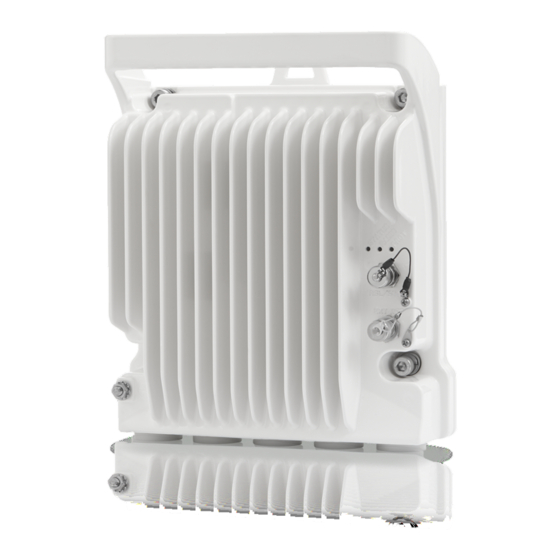
Chapter 2: Product Hardware Description PTP 820C Hardware Overview PTP 820C Hardware Overview PTP 820C features an all-outdoor MultiCore architecture consisting of a single unit directly mounted on the antenna. Figure 1 PTP 820C Rear View (Left) and Front View (Right) -
Page 27: Ptp 820C Interfaces
Chapter 2: Product Hardware Description PTP 820C Hardware Overview PTP 820C Interfaces Figure 3 PTP 820C Interfaces • Data Port 1 for GbE traffic: Electric: 10/100/1000Base-T. Supports PoE. Optical: 1000Base-SX (or X-LX-ZX/XD) • Data Port 2 for GbE traffic: Electric: 10/100/1000Base-T Optical: 1000Base-SX (or X-LX-ZX/XD) •... -
Page 28: Multicore Mediation Devices (Mcmd)
PTP 820C on a standard RFU-C antenna. PTP 820C is equipped with two antenna ports, which mandates the use of the following MCMDs for direct mount connections. The specific MCMDs depend on the configuration. - Page 29 Chapter 2: Product Hardware Description MultiCore Mediation Devices (MCMD) Figure 5 OMT phn-3962 004v000 Page 2-5...
-
Page 30: Poe Injector
Chapter 2: Product Hardware Description PoE Injector PoE Injector The PoE injector is an outdoor unit which can be mounted on a wall, pole, or indoor rack. Each PoE Injector kit includes the following items: • PoE injector • 2 DC power connectors Figure 6 PoE Injector The PoE Injector model available: •... -
Page 31: Figure 7 Poe Injector Ports
Chapter 2: Product Hardware Description PoE Injector Figure 7 PoE Injector Ports phn-3962 004v000 Page 2-7... -
Page 32: System Components
Chapter 2: Product Hardware Description System Components System Components The following figures show the main components used in the PTP 820C installation procedures. Note The availability of the installation components follows the PTP 820C frequency rollout as stated in the published roadmap. - Page 33 Chapter 2: Product Hardware Description System Components phn-3962 004v000 Page 2-9...
-
Page 34: Adaptors And Installation Kits
PTP 820C DUAL SPLITTER KIT N230082L033A N260082L027A N280082L036A N320082L020A N380082L044A PTP 820C SPLITTER KIT N230082L035A N260082L029A N280082L038A N320082L022A N380082L046A PTP 820C OMT KIT N230082L034A N260082L028A N280082L037A N320082L021A N380082L045A PTP 820C DUAL CORE MD KIT N230082L031A N260082L025A N280082L034A N320082L018A N380082L042A phn-3962 004v000 Page 2-10... -
Page 35: Table 4 Remote Mount - 6 To 15 Ghz
6 GHz 7 GHz - 8GHz 10 GHz - 11GHz 13 GHz 15 GHz RFU-C REMOTE MOUNT N000082L121A N000082L121A N000082L121A N000082L121A N000082L121A PTP 820C DC REMOTE N000082L120A N000082L120A N000082L120A N000082L120A N000082L120A MOUNT KIT RFU-C WG Kit N060082L156A N070082L004A N110082L105A N130082L070A... -
Page 36: Antenna Circ Adaptors
Chapter 2: Product Hardware Description Adaptors and Installation Kits Antenna Circ Adaptors Table 6 Antenna circ. Adaptors for 6 to 18GHz Antenna Circ. 6 GHz 7 GHz - 8GHz 10 GHz - 11GHz 13 GHz 15 GHz 18 GHz Adapters for OMT N060082L147A N070082L303A N110082L092A... -
Page 37: Antenna Connection
Chapter 2: Product Hardware Description Antenna Connection Antenna Connection PTP 820C can be mounted directly for all frequencies (6 GHz - 38 GHz) using the following antenna types (for integrated antennas, specific antennas part numbers are required): • CommScope: VHLP series •... - Page 38 Chapter 2: Product Hardware Description Antenna Connection Note Appropriate lubricant or grease can be applied to the screws that connect the PTP 820C to the antenna interface. phn-3962 004v000 Page 2-14...
-
Page 39: Power Specs
Chapter 2: Product Hardware Description Power Specs Power Specs Electrical Requirements • -48V DC Nominal • Maximum current rating 1.5 A • Maximum Cable length 300 meter • Maximum cable size for PoE cable is 24 AWG, with maximum current up to 2A from the power source. -
Page 40: Chapter 3: Cable Installation And Grounding
Chapter 3: Cable Installation and Grounding This chapter describes the installation procedure of the PTP 820C product. This chapter consists of the following sections: • Minimum and Maximum Cable Diameter • Cable Grounding • Surge Protection • Available Cable Options •... -
Page 41: Minimum And Maximum Cable Diameter
To fit the gland, the outer cable diameter should be between 6-10 mm. This applies to all glands on both the PTP 820C unit and the PoE Injector. To fit the grounding clamp, the outer diameter of CAT5E Ethernet cable must be between 6- 7.1mm. -
Page 42: Cable Grounding
Chapter 3: Cable Installation and Grounding Cable Grounding Cable Grounding Cables must be grounded as follows: • For Fiber cables (see Connecting an Optical Fiber Cable and SFP on page3-21), no grounding is required. • For DC power cables (see connecting a DC power cable on page 3-25 ), no grounding is required. - Page 43 Chapter 3: Cable Installation and Grounding Cable Grounding To connect the grounding kit: 1. Strip the cable jacket. 2. Place the cable in the middle of the grounding bracket. 3. Close the grounding bracket around the cable. 4. Tighten the two screws to secure the grounding bracket around the cable. phn-3962 004v000 Page 3-4...
- Page 44 Chapter 3: Cable Installation and Grounding Cable Grounding 5. Install the grounding lug on the grounding bar, or directly to the tower. 6. Tighten the grounding lug. phn-3962 004v000 Page 3-5...
-
Page 45: Grounding The Ptp 820C Unit
Metric wrench 10mm Procedure On the front of each PTP 820C unit, loosen the nut, plain washer and serrated washer from the GND stud, using the metric offset hexagon key and the wrench. Place the cable lug (supplied with the PTP 820C grounding kit) in place on the screw. - Page 46 Chapter 3: Cable Installation and Grounding Cable Grounding A 2-pole circuit breaker, a branch circuit protector, suitably certified in accordance with applicable national code and regulations, rated maximum 20A, must be installed for full power disconnection in a building installation. Any outdoor antenna cable shield must always be connected to protective earth in a building installation.
-
Page 47: Grounding For Multicore Mediation Devices
When the user performs the PTP 820C grounding procedure described in Grounding Procedure, connect the other end of the Grounding Jumper to the PTP 820C grounding screw, along with the PTP 820C grounding cable. The order in which you place the two cables is not important. PTP 820C... - Page 48 The power supply must have grounding points on the AC and DC sides. Caution The user power supply GND must be connected to the positive pole in the PTP 820C power supply. Any other connection may cause damage to the system.
-
Page 49: Surge Protection
Surge Protection Surge Protection PTP 820C includes built-in surge protection for its Ethernet and power interfaces. PTP 820C’s surge protection implementation complies with the standards set forth in the Surge Protection requirements section of the PTP 820C Technical Description, provided the Ethernet cables were... -
Page 50: Available Cable Options
Chapter 3: Cable Installation and Grounding Available Cable Options Available Cable Options Fiber Optic Cables Table 11 Fiber Optic cables part numbers Marketing P/N Description N000082L139A PTP 820 Optical cable, SM, 30m N000082L140A PTP 820 Optical cable, SM, 50m N000082L141A PTP 820 Optical cable, SM, 80m N000082L142A PTP 820 Optical cable, SM, 100m... -
Page 51: Cables For Mimo Connections
Cables for MIMO Connections Table 13 Cables for MIMO connections part numbers Marketing P/N Description N000082L060A PTP 820C MIMO or Prot management cable 10m N000082L061A PTP 820C MIMO or Prot management cable 1m N000082L062A PTP 820C MIMO or Prot management ODU spltr... -
Page 52: Outdoor Ethernet Cable Specifications
Chapter 3: Cable Installation and Grounding Available Cable Options Figure 10 Ethernet cable design • [1]Conductor • [2]Insulation • [3]Screen: Alu/Pet foil. Alu outside • [4]Tinned copper braid • [5]Jacket Table 15 Ethernet cable color code Pair Wire A Wire B WHITE-blue BLUE WHITE-orange... -
Page 53: Outdoor Dc Cable Specifications
Chapter 3: Cable Installation and Grounding Available Cable Options Electrical Requirements Stranding Solid Voltage rating Shielding Tinned copper Braid (Coverage: >80%) = Alluminum Foil Pinout Mechanical/ Environmental Requirements Jacket UV resistant Outer diameter 7.1mm (in order to be compatible with the grounding clamp, CAT5E gnd kit) Operating and Storage -40°C - 85°C... - Page 54 Chapter 3: Cable Installation and Grounding Available Cable Options Electrical Requirements Voltage rating 600V Spark test Dielectric strength 2KV AC min Mechanical/ Environmental Requirements Jacket UV resistant Outer diameter 7-10 mm Operating and Storage -40°C - 85°C temperature range Flammability rating According to UL-1581 VW1, IEC 60332-1 RoHS According to Directive/2002/95/EC...
-
Page 55: Securing The Cables
Chapter 3: Cable Installation and Grounding Securing the Cables Securing the Cables All cables must be secured at every meter on-site using either a T-Rups kit or cable clamps. When using the T-Rups kit, take special care to apply the proper amount of force in order to avoid damage to the cable. -
Page 56: Special Instructions For Use Of Glands
Special Instructions for use of Glands Special Instructions for use of Glands Note Each PTP 820C unit is supplied with two glands. If additional glands are required, they must be ordered separately, in kits of five glands each. Table 18 Ethernet cable part numbers... -
Page 57: General Installation Procedure
Chapter 3: Cable Installation and Grounding Special Instructions for use of Glands Figure 12 Removing glands General Installation Procedure This procedure applies to all cable types, and explains how to install the cables using long glands. The gland is supplied pre-assembled. phn-3962 004v000 Page 3-18... - Page 58 Chapter 3: Cable Installation and Grounding Special Instructions for use of Glands Before inserting a cable, you must disassemble the gland cap and gland rubber from the gland body. Slide the gland cap into the cable. Slide the gland rubber into the cable. phn-3962 004v000 Page 3-19...
- Page 59 Chapter 3: Cable Installation and Grounding Special Instructions for use of Glands Slide the cable into the body of the gland. If a gland cap is being used (see Step 5), make sure to leave enough space for the gland cap to fit into the gland without disturbing the cable. Optionally, after securing the cable into the body of the gland, close the other side of the gland with an M28 gland cap.
- Page 60 Chapter 3: Cable Installation and Grounding Special Instructions for use of Glands If an M28 gland cap is used to close the gland when raising the gland and cable to the radio 1 1 B unit, remove the gland cap from the gland at this point by unscrewing the cap. Connect the cable to the port.
- Page 61 Chapter 3: Cable Installation and Grounding Special Instructions for use of Glands Tighten the rear portion of the gland onto the main part of the gland and make sure that the main 1 5 B part of the gland does not have an additional swivel after the rear portion is secured. Note If the main portion of the gland is rotated while the rear portion is seizing the cable, this may ruin the cable connector.
-
Page 62: Connecting An Optical Fiber Cable And Sfp
Chapter 3: Cable Installation and Grounding Connecting an Optical Fiber Cable and SFP Connecting an Optical Fiber Cable and SFP To connect an optical fiber cable and the SFP transceiver: Use a pre-assembled cable. 1 7 B Split the connector into two separate LC Connectors (one for each fiber). 1 8 B Remove the gland cap and rubber from the gland body. - Page 63 Note A new tie wrap must be used to secure the cable to the gland at the end of the procedure, as described in Step 13. Connect the connector into the PTP 820C plug connector. 2 6 B phn-3962 004v000...
- Page 64 Chapter 3: Cable Installation and Grounding Connecting an Optical Fiber Cable and SFP Tighten the gland to the radio unit until there is full contact between the gland and the radio unit. 2 7 B Tighten the gland cap. 2 8 B Note Before tightening the gland, make sure the gland is aligned with the taped hole in the unit.
- Page 65 Chapter 3: Cable Installation and Grounding Connecting an Optical Fiber Cable and SFP Secure the cable to the gland using a tie wrap. 2 9 B phn-3962 004v000 Page 3-26...
-
Page 66: Connecting A Dc Power Cable
Chapter 3: Cable Installation and Grounding Connecting a DC Power Cable Connecting a DC Power Cable To connect a DC power cable: Strip off 45 mm from the cable jacket. 3 0 B Expose 10 mm at the edge of each of the two wires. 3 1 B Insert the power cable into the gland. - Page 67 Chapter 3: Cable Installation and Grounding Connecting a DC Power Cable Tighten the two top screws. 3 5 B Plug the power cable with connector into the PTP 820C power connector. 3 6 B Tighten the two front screws. 3 7 B...
- Page 68 Chapter 3: Cable Installation and Grounding Connecting a DC Power Cable Note Before tightening the gland, make sure the gland is even with the cover. Tighten the gland gently and make sure there is no resistance. If there is resistance, stop immediately and verify that the gland is not being inserted at an angle.
-
Page 69: Connecting The Ethernet Cable
Chapter 3: Cable Installation and Grounding Connecting the Ethernet Cable Connecting the Ethernet Cable Note To ensure proper grounding and connectivity, it is recommended to use pre- assembled Ethernet cables. Preparing the Ethernet Cable and Plug-in Field Note To ensure proper grounding, the RJ-45 plug must be shielded, with a crimping tail. Table 19 Materials for preparing Ethernet Data Cables Marketing P/N Description... - Page 70 Chapter 3: Cable Installation and Grounding Connecting the Ethernet Cable To prepare the Ethernet cable and plug-in field: Prepare the gland and insert the cable, as described in General Installation Procedure. 4 1 B Strip off approximately 45 mm of the outer insulation jacket from the CAT5E cable. 4 2 B Do not strip off the end of the cableshield, but rather, twist the shield to form a braid.
- Page 71 Chapter 3: Cable Installation and Grounding Connecting the Ethernet Cable Trim all wires to the same length. About 12 mm on the left must be exposed from the inner 4 6 B sheath. Separate the wires and place the twisted shield between the separated wires. 4 7 B Insert the wires into the RJ45 plug.
- Page 72 Chapter 3: Cable Installation and Grounding Connecting the Ethernet Cable Wrap the twisted braid firmly around the cable jacket and let the crimping tail of the RJ45 plug 5 0 B envelop it. Note To ensure proper grounding, it is essential that the twisted braid be firmly connected to the RJ45 plug.
-
Page 73: Preparing The Ethernet Cable Already Assembled
Chapter 3: Cable Installation and Grounding Connecting the Ethernet Cable Preparing the Ethernet Cable Already Assembled To prepare the Ethernet cable already assembled: Release the gland cap and the gland rubber slightly. 5 4 B Insert the CAT5E cable into the gland cap and into the rubber gland. 5 5 B Insert the CAT5E cable into the gland body. -
Page 74: Connection Of Ethernet Cable To Ptp 820C
Connection of Ethernet Cable to PTP 820C To connect the Ethernet cable to the PTP 820C: Remove the relevant cap from the PTP 820C radio. You can use the side of the gland to 5 7 B unscrew the cap. - Page 75 Chapter 3: Cable Installation and Grounding Connecting the Ethernet Cable Tighten the gland cap. 6 0 B Secure the cable to the gland using a tie wrap. 6 1 B phn-3962 004v000 Page 3-36...
-
Page 76: Management Connection For 4X4 Mimo And 1+1/2+2 Hsb Configurations
HSB Configurations In 4x4 MIMO and all HSB protection configurations, two Y-splitter cables and a special signaling cable must be used to connect the management ports (MGT/PROT) of the two PTP 820C units and provide management access to each unit. -
Page 77: Connecting The Mimo/Protection Splitters And Protection Signaling Cable
Connecting the MIMO/Protection Splitters and Protection Signaling Cable Each splitter has three ports: • System plug (“Sys”) – The system plug should be connected to the PTP 820C’s management port. • Management port (“Mng”) – A standard CAT5E cable should be connected to the splitter’s management port in order to utilize out-of-band (external) management. - Page 78 Chapter 3: Cable Installation and Grounding Management Connection for 4x4 MIMO and 1+1/2+2 HSB Configurations Figure 13 4x4 MIMO or HSB Protection Configuration with External Management phn-3962 004v000 Page 3-39...
-
Page 79: Chapter 4: Poe Injector Installation And Connection
Chapter 4: PoE Injector Installation and Connection This chapter describes the PoE Injector installation and connection procedure of the PTP 820C product. This chapter consists of the following sections: • PoE Injector Cable Connection • PoE Injector Grounding • PoE Injector 19” Rack Installation •... -
Page 80: Poe Injector Cable Connection
3-27. • The total length of the cable between the PTP 820C port and the Switch/Router the device is connected to must not exceed 100m/328ft. This length includes the connection between the PTP 820C and the PoE Injector (X1 + X2 ≤ 100m/328ft in the figure below). -
Page 81: Poe Injector Grounding
Chapter 4: PoE Injector Installation and Connection PoE Injector Grounding PoE Injector Grounding To ground the PoE Injector: On the right side of each PoE Injector, loosen the screw, plain washer, and serrated washer. 6 2 B Place the cable lug (supplied with the PoE injector kit) between the plain and serrated washer. 6 3 B Tighten the screw. -
Page 82: Poe Injector 19" Rack Installation
Chapter 4: PoE Injector Installation and Connection PoE Injector 19” Rack Installation PoE Injector 19” Rack Installation List of Items Table 20 Required items for PoE Injector 19” rack installation Item Description Quantity Remarks PoE Injector PoE Injector 19” Rack Mount Kit Required Tools •... -
Page 83: Procedure
Chapter 4: PoE Injector Installation and Connection PoE Injector 19” Rack Installation Procedure To mount the PoE Injector on a rack: Mount the PoE Injector to a 19” rack using a 19” rack adaptor. 6 6 B Mount the PoE Injector on the 19” adaptor through the wall mounting holes, using M6 screws 6 7 B and washers. - Page 84 Chapter 4: PoE Injector Installation and Connection PoE Injector 19” Rack Installation Mount the 19” rack adaptor to a 19” rack using four M6 screws and cage nuts. 6 8 B phn-3962 004v000 Page 4-6...
-
Page 85: Poe Injector Etsi Rack Installation
Chapter 4: PoE Injector Installation and Connection PoE Injector ETSI Rack Installation PoE Injector ETSI Rack Installation List of Items Table 21 Required items for PoE Injector ETSI rack installation Item Description Quantity Remarks PoE Injector PoE Injector ETSI Rack Mount Kit Required Tools •... - Page 86 Chapter 4: PoE Injector Installation and Connection PoE Injector ETSI Rack Installation Mount the PoE Injector on the adaptor through the wall mounting holes using M6 screws and 7 1 B washers. Mount the 19” rack adaptor with the ETSI ears on the ETSI rack using four M6 screws and 7 2 B cage nuts.
-
Page 87: Chapter 5: Generic Installation Procedures
Chapter 5: Generic Installation Procedures This chapter describes generic installation procedures of PTP 820C product. This chapter consists of the following sections: • General Notes Concerning All Installation Procedures • Torque Requirements • PTP 820C DC Pole Mount Procedure •... -
Page 88: General Notes Concerning All Installation Procedures
2+0 SP installation, if you want to install a 1+0 SP HW ready for 2+0 SP. One of the major benefits of the PTP 820C and the dual core architecture is that upgrading can be done remotely by uploading the correct software license. -
Page 89: Torque Requirements
Chapter 5: Generic Installation Procedures Torque Requirements Torque Requirements When tightening the captive screws, use 20 Nm torque for radio-antenna, radio-mediation device, and mediation device-antenna connections. In order to avoid misalignment, screws should be tightened progressively. When fastening a waveguide to the radio or mediation device, use the following torque, according to frequency and screw type: •... -
Page 90: Ptp 820C Dc Pole Mount Procedure
Marketing P/N Description N000082L120A PTP 820C DC Remote Mount Kit N060082L002A PTP 820C 6 GHz Remote Mount adaptor - UDR70 N070082L001A PTP 820C 7-8 GHz Remote Mount adaptor - UBR84 N110082L001A PTP 820C 10-11 GHz Remote Mount adaptor - UBR100... -
Page 91: 6-13 Ghz Installation Procedure
Chapter 5: Generic Installation Procedures PTP 820C DC Pole Mount Procedure Mount and tighten the PTP 820C DC pole mount to a pole with a diameter of 114 mm using 7 3 B the four washers and screws supplied with the PTP 820C DC pole mount kit... -
Page 92: Remote Mount Installation For Single Polarization With An Remote Mount Kit
N130082L002A PTP 820 RFU-C ADPT 13GHz Remote Mount Adaptor - UBR120 N000082L121A P 820 RFU-C Pole Mount kit N060082L138A PTP 820C Splitter Kit 6 GHz N070082L295A PTP 820C Splitter Kit 7-8 GHz N110082L083A PTP 820C Splitter Kit 10-11 GHz N130082L057A... -
Page 93: 6-13 Ghz Installation Procedure
Chapter 5: Generic Installation Procedures Remote Mount Installation for Single Polarization with an Remote Mount kit 6-13 GHz Installation Procedure Mount and tighten the RFU-C Adaptor plate (supplied in RFU-C Adaptation kit to RFU-C 7 5 B Adaptor Remote Mount Kit) to the RFU-C Remote Pole Mount using the four flat screws supplied with the RFU-C Adaptation kit to RFU-C Adaptor Remote Mount Kit. - Page 94 7 6 B captive screws and washers that are assembled to the PTP 820C Splitter kit. Mount and tighten the PTP 820C radio to the PTP 820C Splitter using the four captive screws 7 7 B and washers that are assembled to the PTP 820C radio. Pay attention that the O-rings are mounted on the PTP 820C Splitter kit.
- Page 95 Chapter 5: Generic Installation Procedures Remote Mount Installation for Single Polarization with an Remote Mount kit Connect the Flexible Waveguide and Sealing Gasket supplied with the RFU-C Adaptor Remote 7 8 B Mount Kit to the RFU-C Adaptor plate. Tighten the four screws supplied with the RFU-C Adaptor Remote Mount Kit.
-
Page 96: 15-38 Ghz Installation Procedure
Loosen the two screws, and remove the twist plate from the PTP 820C Splitter. 7 9 B Mount and tighten the PTP 820C Splitter to the RFU-C Remote Pole Mount using the four 8 0 B captive screws and washers that are assembled to the PTP 820C Splitter kit. - Page 97 Remote Mount Installation for Single Polarization with an Remote Mount kit Mount and tighten the PTP 820C radio to the PTP 820C Splitter using the four captive screws 8 1 B and washers that are assembled to the PTP 820C radio. Make sure the O-rings are mounted on the PTP 820C Splitter kit.
- Page 98 Chapter 5: Generic Installation Procedures Remote Mount Installation for Single Polarization with an Remote Mount kit phn-3962 004v000 Page 5-12...
-
Page 99: Management Connection For Mimo And Protection Configurations
This option must be used when you plan to manage the system using in-band management. The MIMO/Protection signaling cable must be connected between the management ports of two PTP 820C units operating in either MIMO or HSB protection mode. The physical cable connection phn-3962 004v000... -
Page 100: Connecting A Mimo/Protection Splitter
The splitter has three ports, as shown in the following figure. Figure 15 MIMO/Protection signaling cable 2 • System plug (“Sys”) – The system plug must be connected to the PTP 820C’s management port. • Management port (“Mng”) – A standard CAT5E cable must be connected to the splitter’s management port in order to utilize out-of-band (external) management. -
Page 101: Figure 16 Mimo/Protection Signaling Cable 3
Chapter 5: Generic Installation Procedures Management Connection for MIMO and Protection Configurations Figure 16 MIMO/Protection signaling cable 3 phn-3962 004v000 Page 5-15... -
Page 102: Chapter 6: Installation Procedures Per Configuration Type
Chapter 6: Installation Procedures per Configuration Type This chapter describes the installation procedures per configuration type of the PTP 820C product. This chapter consists of the following sections: • MultiCore 2+0 Dual Polarization Direct Mount • MultiCore 2+0 Dual Polarization Remote Mount •... -
Page 103: Multicore 2+0 Dual Polarization Direct Mount
List of Items Table 24 Required items for MultiCore 2+0 Dual Polarization Direct Mount Item Description Quantity Remarks PTP 820C RADIO PTP 820C OMT kit CIRC./CIRC. ADAPTOR Per Antenna Vendor Required Tools • Metric offset hexagon key set • Metric wrench key set... -
Page 104: Insertion Loss
23-26 28-38 Devices Path/Remarks 6-8 GHz 11 GHz 18 GHz Each PTP 820C antenna port to Mediation device antenna port Procedure Prior to the installation, follow the antenna manufacturer’s instructions to use the circular 8 3 B adaptor. (Remove the existing rectangular transition, swap the O-ring and install the circular transition instead.) - Page 105 Connect the OMT Kit to the antenna and secure it with four screws. Verify the existence of the 8 4 B O-ring Connect the PTP 820C radio to the OMT Kit using the four M8 captive screws and washers 8 5 B supplied and tighten the screws.
-
Page 106: Multicore 2+0 Dual Polarization Remote Mount
PTP 820C RADIO Not used for standard interface PTP 820C OMT kit antennas (six feet and larger). FLEXIBLE WG KIT PTP 820C DC POLE MOUNT KIT PTP 820C DC REMOTE MOUNT From 6-13GHz ADAPTOR KIT Per Antenna Vendor. Not used for Circ./Circ. -
Page 107: Required Tools
1315 23-26 28-38 Devices Path/Remarks 6-8 GHz 11 GHz 18 GHz Each PTP 820C OMT and antenna port to two WGs Mediation device antenna port Common Installation Prior to the installation, follow the antenna manufacturer’s instructions to use the circular 8 6 B adaptor. - Page 108 Connect the OMT Kit to the antenna and secure it with four screws. Verify the existence of the 8 7 B O-ring. Mount and tighten the O-ring and the Flexible WG to PTP 820C OMT ports using the four 8 8 B screws supplied with the Flexible WG kit.
-
Page 109: 6-13 Ghz
Mount and tighten the PTP 820C Remote Mount Adaptor plate (supplied in PTP 820C Adaptor 8 9 B Remote Mount kit) to the PTP 820C Pole Mount using the four flat screws supplied with the PTP 820C Adaptor Remote Mount kit. - Page 110 9 1 B Adaptor ports using the four screws supplied with each Flexible WG kit. 15-38 GHz Mount and tighten the PTP 820C to the PTP 820C DC Pole Mount using the four screws 9 2 B assembled on the PTP 820C.
- Page 111 Chapter 6: Installation Procedures per Configuration Type MultiCore 2+0 Dual Polarization Remote Mount Mount and tighten the O-ring and the Flexible WG to PTP 820C radio ports using the four 9 3 B screws supplied with the Flexible WG kit.
-
Page 112: Multicore 2+0 Single Polarization Direct Mount
List of Items Table 28 Required item for MultiCore 2+0 Single Polarization Direct Mount Item Description Quantity Remarks PTP 820C RADIO PTP 820C Splitter KIT Required Tools • Metric offset hexagon key set • Phillips #1 and #2 screwdriver Insertion Loss... -
Page 113: Procedure
Mount and tighten the PTP 820C Splitter Kit on the antenna using the four M8 screws and 9 5 B washers. Mount and tighten the PTP 820C to the PTP 820C Splitter Kit using the four M8 captive screws 9 6 B and washers supplied. -
Page 114: Multicore 2+0 Single Polarization Remote Mount
Description Quantity Remarks PTP 820C RADIO RFU-C ADAPTOR REMOTE MOUNT KIT 1 From 6-13 GHz RFU-C POLE MOUNT KIT PTP 820C SPLITTER KIT FLEXIBLE WG KIT Required Tools • Metric offset hexagon key wrench set • Phillips #1, #2 screwdriver •... -
Page 115: Insertion Loss
Chapter 6: Installation Procedures per Configuration Type MultiCore 2+0 Single Polarization Remote Mount Insertion Loss Table 31 Insertion loss for MultiCore 2+0 Single Polarization Remote Mount Insertion Loss [dB] Mediation Signal 1315 23-26 28-38 Devices Path/Remarks 6-8 GHz 11 GHz 18 GHz Splitter and Radio to antenna... -
Page 116: 6-13 Ghz
Remote Mount kit) to the RFU-C Pole Mount using the four flat screws supplied with the RFU- C Adaptor Remote Mount kit. Mount and tighten the PTP 820C Splitter to the RFU-C Pole Mount using the four captive 9 8 B screws and washers that are assembled to the PTP 820C Splitter kit. - Page 117 MultiCore 2+0 Single Polarization Remote Mount Mount and tighten the PTP 820C to the PTP 820C Splitter using the four captive screws and 9 9 B washers that are assembled to the PTP 820C radio. Pay attention that the O-rings are mounted on the PTP 820C Splitter kit.
-
Page 118: 15-38 Ghz
Loosen the two screws and remove the twist plate from the PTP 820C Splitter. 1 0 1 B Mount and tighten the PTP 820C Splitter to the RFU-C Pole Mount using the four captive 1 0 2 B screws and washers that are assembled to the PTP 820C Splitter kit. - Page 119 MultiCore 2+0 Single Polarization Remote Mount Mount and tighten the PTP 820C to the PTP 820C Splitter using the four captive screws and 1 0 3 B washers that are assembled to the PTP 820C. Pay attention that the O-rings are mounted on the PTP 820C Splitter kit.
-
Page 120: Multicore 2+2 Hsb Double Polarization Direct Mount
Table 32 Required items for MultiCore 2+2 HSB Double Polarization Direct Mount Item Description Quantity Remarks PTP 820C RADIO PTP 820C OMT KIT PTP 820C DUAL COUPLER KIT CIRC./CIRC. ADAPTOR Per Antenna Vendor Required Tools • Metric offset hexagon key set •... -
Page 121: Insertion Loss
1 0 5 B adaptor. (Remove the existing rectangular transition, swap the O-ring, and install the circular transition instead.) Connect the PTP 820C OMT Kit to the antenna and secure it with four screws. Verify existence 1 0 6 B of the O-ring. - Page 122 1 0 7 B and tighten the screws. Mount and tighten the PTP 820C radio unit to both sides of the Dual Coupler Kit using the 1 0 8 B supplied captive screws and washers. Pay attention that the O-rings are correctly mounted on the radio ports of the PTP 820C Dual Coupler.
- Page 123 Chapter 6: Installation Procedures per Configuration Type MultiCore 2+2 HSB Double Polarization Direct Mount Connect the MIMO signaling cable between the management ports of both units. For 1 0 9 B (See preparing a MIMO/ additional instructions on preparing and connecting this cable. protection signaling cable on page 3-35 phn-3962 004v000...
-
Page 124: Multicore 2+2 Hsb Double Polarization Remote Mount
Description Quantity Remarks PTP 820C RADIO PTP 820C OMT KIT PTP 820C DUAL COUPLER KIT FLEXIBLE WG KIT PTP 820C DC POLE MOUNT KIT PTP 820C DC REMOTE MOUNT From 6-13GHz ADAPTOR KIT CIRC./CIRC. ADAPTOR Per Antenna Vendor. Required Tools •... -
Page 125: Insertion Loss
Chapter 6: Installation Procedures per Configuration Type MultiCore 2+2 HSB Double Polarization Remote Mount • Phillips #1 , #2 screwdriver Insertion Loss Table 35 Insertion loss for MultiCore 2+2 HSB Double Polarization Remote Mount Insertion Loss [dB] Mediation Signal 13-15 23-26 28-38 Devices... - Page 126 Connect the OMT Kit to the antenna and secure it with four screws. Verify the existence of the 1 1 1 B O-ring. Mount and tighten the O-ring and the Flexible WG to PTP 820C OMT ports using the four 1 1 2 B screws supplied with the Flexible WG kit.
- Page 127 Chapter 6: Installation Procedures per Configuration Type MultiCore 2+2 HSB Double Polarization Remote Mount Connect the protection signaling cable between the management ports of both units. For 1 1 3 B additional instructions on preparing and connecting this cable, refer to Preparing a MIMO/ Protection signaling cable on page 3-35.
-
Page 128: 6-13 Ghz
Mount and tighten the PTP 820C Remote Mount Adaptor plate (supplied in PTP 820C Adaptor 1 1 4 B Remote Mount kit) to the PTP 820C Pole Mount using the four flat screws supplied with the PTP 820C Adaptor Remote Mount kit. - Page 129 MultiCore 2+2 HSB Double Polarization Remote Mount Mount and tighten the PTP 820C radios on each side of the PTP 820C Dual Coupler using the 1 1 6 B screws assembled on PTP 820C radio. Pay attention that the O-rings are correctly assembled on the radio port of the PTP 820C Dual coupler.
- Page 130 1 1 8 B screws and washers supplied with PTP 820C Dual Coupler kit. Mount and tighten the PTP 820C radios on each side of the PTP 820C Dual Coupler using the 1 1 9 B screws assembled on PTP 820c radio. Pay attention that the O-rings are correctly assembled on the radio port of the PTP 820C Dual coupler.
- Page 131 Chapter 6: Installation Procedures per Configuration Type MultiCore 2+2 HSB Double Polarization Remote Mount Mount the O-ring and the Flexible WG to PTP 820C Dual Coupler ports using the four screws 1 2 0 B supplied with the Flexible WG kit.
-
Page 132: Multicore 2+2 Hsb Single Polarization Direct Mount
List of Items Table 36 Required items for MultiCore 2+2 HSB Single Polarization Direct Mount Item Description Quantity Remarks PTP 820C RADIO PTP 820C SPLITTER KIT DUAL COUPLER KIT Required Tools • Metric offset hexagon key set • Metric wrench key set •... - Page 133 Chapter 6: Installation Procedures per Configuration Type MultiCore 2+2 HSB Single Polarization Direct Mount Insertion Loss [dB] Mediation Signal 13-15 23-26 28-38 Devices Path/Remarks 6-8 GHz 11 GHz 18 GHz Double Coupler Secondary Paths and Splitter phn-3962 004v000 Page 6-32...
-
Page 134: Procedure
Chapter 6: Installation Procedures per Configuration Type MultiCore 2+2 HSB Single Polarization Direct Mount Procedure Adjust the twist on the Splitter Kit. Perform one of the following steps, according to the 1 2 1 B required polarization (horizontal or vertical). For horizontal polarization, locate the holes above and below the letter “H”... - Page 135 Chapter 6: Installation Procedures per Configuration Type MultiCore 2+2 HSB Single Polarization Direct Mount Connect the PTP 820C Dual Coupler Kit to the PTP 820C Splitter Kit using four M8 screws and 1 2 3 B washers and tighten the screws.
- Page 136 Chapter 6: Installation Procedures per Configuration Type MultiCore 2+2 HSB Single Polarization Direct Mount Connect the protection signaling cable between the management ports of both units. For 1 2 5 B additional instructions on preparing and connecting this cable, Preparing a MIMO/ on page 3-35 Protection signaling cable phn-3962 004v000...
-
Page 137: Multicore 2+2 Hsb Single Polarization Remote Mount
Table 38 Required items for MultiCore 2+2 HSB Single Polarization Remote Mount Item Description Quantity Remarks PTP 820C RADIO PTP 820C SPLITTER KIT PTP 820C DUAL COUPLER KIT FLEXIBLE WG KIT RFU-C POLE MOUNT KIT RFU-C REMOTE MOUNT ADAPTOR From 6-13 GHz. Required Tools •... -
Page 138: Insertion Loss
Chapter 6: Installation Procedures per Configuration Type MultiCore 2+2 HSB Single Polarization Remote Mount Insertion Loss Table 39 Insertion loss for MultiCore 2+2 HSB Single Polarization Remote Mount Insertion Loss [dB] Mediation Signal 1315 23-26 28-38 Devices Path/Remarks 6-8 GHz 11 GHz 18 GHz Main Paths... - Page 139 1 2 7 B screws and washers that are assembled to the PTP 820C Splitter kit. Mount and tighten the PTP 820C Dual Coupler to the PTP 820C Splitter using the four captive 1 2 8 B screws and washers that are supplied with the PTP 820C Dual Coupler kit. Pay attention that the O-rings are mounted on the PTP 820C Splitter.
- Page 140 MultiCore 2+2 HSB Single Polarization Remote Mount Mount and tighten the PTP 820C Radio to the PTP 820C Dual Coupler using the four screws 1 2 9 B and washers that are assembled to the PTP 820C Radio. Pay attention that the O-rings are mounted on the PTP 820C Dual Coupler.
- Page 141 Chapter 6: Installation Procedures per Configuration Type MultiCore 2+2 HSB Single Polarization Remote Mount Connect the protection signaling cable between the management ports of both units. For 1 3 1 B additional instructions on preparing and connecting this cable, refer to preparing a MIMO protection signalling cable on page 3-35.
-
Page 142: 15-38 Ghz
Loosen the two screws, and remove the twist plate from the PTP 820C Splitter. 1 3 2 B Mount and tighten the PTP 820C Splitter to the RFU-C Pole Mount using the four captive 1 3 3 B screws and washers that are assembled to the PTP 820C Splitter kit. - Page 143 MultiCore 2+2 HSB Single Polarization Remote Mount Mount and tighten the PTP 820C Dual Coupler to the PTP 820C Splitter using the four captive 1 3 4 B screws and washers that are supplied with the PTP 820C Dual Coupler kit. Pay attention that the O-rings are mounted on the PTP 820C Splitter.
- Page 144 Connect the Flexible Waveguide and Sealing Gasket supplied with the Flexible Waveguide Kit 1 3 6 B to the PTP 820C Dual Coupler antenna port. Tighten the four screws supplied with the Flexible Waveguide kit. Connect the protection signaling cable between the management ports of both units. For...
-
Page 145: Multicore 2+0 Dual Polarization Direct Mount
Table 40 Required items for 2 x MultiCore 2+0 Dual Polarization Direct Mount Item Description Quantity Remarks PTP 820C RADIO PTP 820C OMT KIT PTP 820C DUAL COUPLER or SPLITTER KIT CIRC./CIRC. ADAPTOR Per Antenna Vendor Required Tools • Metric offset hexagon key set •... -
Page 146: Insertion Loss
1 3 8 B adaptor. (Remove the existing rectangular transition, swap the O-ring, and install the circular transition instead.) Connect the PTP 820C OMT Kit to the antenna and secure it with four screws. Verify existence 1 3 9 B of the O-ring. - Page 147 1 4 0 B and tighten the screws. Mount and tighten the PTP 820C DC radio unit to both sides of the PTP 820C Dual Coupler 1 4 1 B using the supplied captive screws and washers. Pay attention that the O-rings are correctly mounted on the radio ports of the PTP 820C Dual Coupler.
-
Page 148: Multicore 2+0 Dual Polarization Remote Mount
Table 42 Required items for MultiCore 2+0 HSB Dual Polarization Remote Mount Item Description Quantity Remarks PTP 820C RADIO PTP 820C OMT KIT PTP 820C DUAL COUPLER OR DUAL SPLITTER KIT FLEXIBLE WG KIT PTP 820C DC POLE MOUNT KIT PTP 820C DC REMOTE MOUNT From 6-13GHz ADAPTOR KIT CIRC./CIRC. -
Page 149: Insertion Loss
Chapter 6: Installation Procedures per Configuration Type 2 x MultiCore 2+0 Dual Polarization Remote Mount Insertion Loss Table 43 Insertion loss for MultiCore 2+0 Dual Polarization Remote Mount Insertion Loss [dB] Mediation Signal 13-15 23-26 28-38 Devices Path/Remarks 6-8 GHz 11 GHz 18 GHz Double... - Page 150 Chapter 6: Installation Procedures per Configuration Type 2 x MultiCore 2+0 Dual Polarization Remote Mount Mount and tighten the O-ring and the Flexible WG to PTP 820C OMT ports using the four 1 4 4 B screws supplied with the Flexible WG kit.
-
Page 151: 6-13 Ghz
Mount and tighten the PTP 820-C Remote Mount Adaptor plate (supplied in PTP 820C Adaptor 1 4 5 B Remote Mount kit) to the PTP 820C Pole Mount using the four flat screws supplied with the PTP 820C Adaptor Remote Mount kit. - Page 152 2 x MultiCore 2+0 Dual Polarization Remote Mount Mount and tighten the PTP 820C radios on each side of the PTP 820C Dual Coupler using the 1 4 7 B screws assembled on PTP 820C radio. Make sure that the O-rings are correctly assembled on the radio port of the PTP 820C Dual Coupler.
-
Page 153: 15-38 Ghz
1 4 9 B screws and washers supplied with PTP 820C Dual Coupler kit. Mount and tighten the PTP 820C radios on each side of the PTP 820C Dual Coupler using the 1 5 0 B screws assembled on PTP 820C radio. Pay attention that the O-rings are correctly assembled on the radio port of the PTP 820C Dual Coupler. - Page 154 Chapter 6: Installation Procedures per Configuration Type 2 x MultiCore 2+0 Dual Polarization Remote Mount Mount the O-ring and the Flexible WG to PTP 820C Dual Coupler ports using the four screws 1 5 1 B supplied with the Flexible WG kit.
-
Page 155: Multicore 2+0 Single Polarization Direct Mount
Table 44 Required items for 2 x MultiCore 2+0 Single Polarization Direct Mount Item Description Quantity Remarks PTP 820C RADIO PTP 820C Splitter Kit PTP 820C Dual Splitter Kit Required Tools • Metric offset hexagon key set • Metric wrench key set •... -
Page 156: Procedure
Chapter 6: Installation Procedures per Configuration Type 2 x MultiCore 2+0 Single Polarization Direct Mount Procedure Adjust the twist on the PTP 820C Splitter Kit. Perform one of the procedures below according 1 5 2 B to the required polarization: Horizontal polarization, locate the holes above and below the letter “H”... - Page 157 Chapter 6: Installation Procedures per Configuration Type 2 x MultiCore 2+0 Single Polarization Direct Mount Connect the PTP 820C Dual Coupler Kit to the PTP 820C Splitter Kit using four M8 screws and 1 5 4 B washers and tighten the screws.
-
Page 158: 2X2 Los Mimo Direct Mount
List of Items Table 46 Required items for 2x2 LoS MIMO Direct Mount Item Description Quantity Remarks PTP 820C Radio PTP 820C Dual Core Kit Flexible WG Kit Optional Coax to WG Kit Optional Required Tools • Metric offset hexagon key set •... -
Page 159: Procedure
Chapter 6: Installation Procedures per Configuration Type 2x2 LoS MIMO Direct Mount Procedure Adjust the twist on the dual core kit according to the required polarization. 1 5 6 B Note Ensure the polarization mounting direction of the twist to the dual core is according to the antenna polarization. - Page 160 Chapter 6: Installation Procedures per Configuration Type 2x2 LoS MIMO Direct Mount Mount and tighten the PTP 820C dual core kit on the antenna using the four M8 screws and 1 5 8 B washers. Note Verify that the O-ring is properly mounted between the antenna transition and the dual core.
- Page 161 Verify that the O-rings are properly mounted between the dual core and the Coax to WG flange. Connect the flexible waveguide to the PTP 820C dual core kit using O-ring, screws and 1 6 1 B washers supplied with flexible waveguide kit and tighten the screws.
- Page 162 Chapter 6: Installation Procedures per Configuration Type 2x2 LoS MIMO Direct Mount You can also connect the dual core flange to coax to WG adapter supplied separately. Place 1 6 2 B O-ring and tighten screws and washers supplied with Coax to WG adapter kit. Note Verify that the O-rings are properly mounted between the dual core and the Coax to WG flange.
-
Page 163: 2X2 Los Mimo Remote Mount
List of Items Table 48 Required items for 2x2 LoS MIMO Remote Mount Item Description Quantity Remarks PTP 820C RADIO PTP 820C REMOTE MOUNT From 6-13GHz ADAPTOR KIT Required Tools • Metric offset hexagon key set • Metric wrench key set... -
Page 164: 6-13 Ghz
Mount and tighten the PTP 820C Remote Mount Adaptor plate (supplied in PTP 820C Adaptor 1 6 3 B Remote Mount kit) to the PTP 820C Pole Mount using the four flat screws supplied with the PTP 820C Adaptor Remote Mount kit. - Page 165 Chapter 6: Installation Procedures per Configuration Type 2x2 LoS MIMO Remote Mount Mount and tighten both Flexible WGs with their O-ring to the PTP 820C Remote Mount 1 6 5 B Adaptor ports using the four screws supplied with each Flexible WG kit.
- Page 166 Chapter 6: Installation Procedures per Configuration Type 2x2 LoS MIMO Remote Mount 15-38 GHz Mount and tighten the PTP 820C radio to the PTP 820C DC Pole Mount using the four screws 1 6 6 B assembled on the PTP 820C radio.
- Page 167 Chapter 6: Installation Procedures per Configuration Type 2x2 LoS MIMO Remote Mount Mount and tighten the O-ring and flexible WG to both antenna ports using the four screws 1 6 8 B supplied with the flexible WG kit. phn-3962 004v000 Page 6-66...
-
Page 168: 4X4 Los Mimo Direct Mount
List of Items Table 50 Required items for 4x4 LoS MIMO Direct Mount Item Description Quantity Remarks PTP 820C RADIO PTP 820C OMT KIT MIMO DATA CABLE SOURCE SHARING CABLE CAT5E MIMO SIGNALING CABLE CIRC./CIRC. ADAPTOR Per Antenna Vendor Required Tools •... -
Page 169: Insertion Loss
Table 51 Insertion loss for 4x4 LoS MIMO Direct Mount Insertion Loss [dB] Mediation Signal 13-15 23-26 28-38 Devices Path/Remarks 6-8 GHz 11 GHz 18 GHz Each PTP 820C OMT for antenna port to each PTP Mediation device 820C antenna port phn-3962 004v000 Page 6-68... -
Page 170: Procedure
For instructions on installation of the PTP 820C OMT and radios, see MultiCore 2+0 Dual 1 6 9 B Polarization Direct Mount on page 6-2. Connect the source sharing cable between both EXT REF PTP 820C radio connectors. 1 7 0 B phn-3962 004v000 Page 6-69... - Page 171 Chapter 6: Installation Procedures per Configuration Type 4x4 LoS MIMO Direct Mount Connect the MIMO data sharing cable between both ETH3/EXT PTP 820C radio connectors. 1 7 1 B Connect the MIMO signaling cable between the management ports of both units. For...
-
Page 172: 4+0 Dual Polarization, 2+2Hsb Single/Dual Polarization Direct Mount
• Metric wrench key set Procedure Once the OMT/Splitter is mounted to the antenna, connect the PTP 820C Dual Coupler/Splitter kit to 1 7 3 B the OMT kit using four M8 screws and washers, and tighten the screws. Caution Verify that the O-ring is properly mounted between the OMT/Splitter ports and the Dual Coupler/Splitter. - Page 173 Chapter 6: Installation Procedures per Configuration Type 4+0 Dual Polarization, 2+2HSB Single/Dual Polarization Direct Mount Connect the PTP 820C DC radios using the four M8 captive screws and washers supplied, and 1 7 4 B tighten the screws. Caution Verify that the O-rings are properly mounted between the Dual Coupler/Splitter ports and the radio.
-
Page 174: 4+0 Dual Polarization, 2+2Hsb Dual Polarization Remote Mount
List of Items Table 53 Required items for 4+0 Dual Polarization, 2+2HSB Dual Polarization Remote Mount Item Description Quantity Remarks PTP 820C OMT Kit Flexible Waveguide Kit PTP 820C Dual Coupler/Splitter Required Tools • Metric offset hexagon key set •... -
Page 175: 6-13Ghz
Mount and tighten the PTP 820C Remote Mount Adaptor plate (supplied in PTP 820C Adaptor 1 7 6 B Remote Mount kit) to the PTP 820C Pole Mount using the four flat screws supplied with the PTP 820C Adaptor Remote Mount kit. - Page 176 4+0 Dual Polarization, 2+2HSB Dual Polarization Remote Mount Mount and tighten the PTP 820C radios on each side of the PTP 820C Dual Coupler using the 1 7 8 B screws assembled on PTP 820C radio. Make sure that the O-rings are correctly assembled on the radio port of the PTP 820C dual coupler.
-
Page 177: 15-38 Ghz
4+0 Dual Polarization, 2+2HSB Dual Polarization Remote Mount 15-38 GHz Mount and tighten the PTP 820C Dual Coupler to the PTP 820C DC Pole Mount using the four 1 8 0 B screws and washers supplied with the PTP 820C Dual Coupler kit. - Page 178 Chapter 6: Installation Procedures per Configuration Type 4+0 Dual Polarization, 2+2HSB Dual Polarization Remote Mount Mount the O-ring and the Flexible Waveguides to the PTP 820C Dual Coupler ports using the four 1 8 2 B screws supplied with the Flexible Waveguide kits.
-
Page 179: 2+2 Hsb Single Polarization Remote Mount
Table 54 Required items for 2+2 HSB Single Polarization Remote Mount Item Description Quantity Remarks PTP 820C RADIO PTP 820C SPLITTER KIT PTP 820C DUAL COUPLER KIT FLEXIBLE WG KIT RFU-C POLE MOUNT KIT Required Tools • Metric offset hexagon key set •... -
Page 180: 6-13Ghz
Remote Mount kit) to the RFU-C Pole Mount using the four flat screws supplied with the RFU- C Adaptor Remote Mount kit. Mount and tighten the PTP 820C Splitter to the RFU-C Pole Mount using the four captive 1 8 5 B screws and washers that are assembled to the PTP 820C Splitter kit. - Page 181 PTP 820C Dual Coupler kit. Make sure that the O-rings are mounted on the PTP 820C Splitter. Mount and tighten the PTP 820C unit to the PTP 820C Dual Coupler using the four screws and 1 8 7 B washers that are assembled to the PTP 820C unit.
- Page 182 Chapter 6: Installation Procedures per Configuration Type 2+2 HSB Single Polarization Remote Mount Connect the Flexible Waveguide and Sealing Gasket supplied with the Flexible Waveguide kit 1 8 8 B to the RFU-C Adaptor plate. Tighten the four screws supplied with the Flexible Waveguide kit. phn-3962 004v000 Page 6-81...
-
Page 183: 1+1 Hsb-Sd
PTP 820C Adaptor Remote Mount kit. Mount and tighten the PTP 820C Dual Coupler to the PTP 820C Pole Mount using the four screws and washers that are supplied with the PTP 820C Dual Coupler kit. Pay attention that the O-rings are mounted on the PTP 820C Remote Mount Adaptor. - Page 184 Chapter 6: Installation Procedures per Configuration Type 1+1 HSB-SD Mount and tighten the PTP 820C radios on each side of the PTP 820C Dual Coupler using the screws assembled on PTP 820C radio. Make sure that the O-rings are correctly assembled on the radio port of the PTP 820C dual coupler.
-
Page 185: 15-42Ghz
1+1 HSB-SD 15-42GHz Mount and tighten the PTP 820C Dual Coupler to the PTP 820C Pole Mount using the four screws and washers supplied with the PTP 820C Dual Coupler kit. Mount and tighten the PTP 820C radios on each side of the PTP 820C Dual Coupler using the screws assembled on the PTP 820C unit. - Page 186 Chapter 6: Installation Procedures per Configuration Type 1+1 HSB-SD Mount the O-ring and the Flexible Waveguides to the PTP 820C Dual Coupler ports using the four screws supplied with the Flexible Waveguide kits. Mount and tighten the O-ring and the Flexible Waveguides to the antenna ports on the primary and diversity antennas using the four screws supplied with the Flexible Waveguide kits.
-
Page 187: Afr 1+0 Hub Site
820C or PTP 820S units are deployed in two tail sites. The hub site utilizes a single PTP 820C unit with two radio carriers. Each carrier is in a link, via its own directional antenna, with a tail site that consists of a PTP 820C or PTP 820S unit. -
Page 188: Insertion Loss
AFR 1+0 Hub Site Insertion Loss Table 57 Insertion Loss for AFR 1+0 Hub Site Mediation Signal Path / Insertion Loss [dB] Devices Remarks 11 GHz 13-15 23-26 28-42 Flex WG (1m) Each PTP 820C port to antenna port phn-3962 004v000 Page 6-87... -
Page 189: Common Installation
Chapter 6: Installation Procedures per Configuration Type AFR 1+0 Hub Site Common Installation Prior to the installation, follow the antenna manufacturer’s instructions to use the circular 1 8 9 B adaptor. (Remove the existing rectangular transition, swap the O-ring, and install the circular transition instead.) Mount and tighten the Flexible WG to the antenna port using the four screws supplied with 1 9 0 B... -
Page 190: 6-13 Ghz
Mount and tighten the PTP 820C Remote Mount Adaptor plate (supplied in PTP 820C Adaptor 1 9 1 B Remote Mount kit) to the PTP 820C Pole Mount using the four flat screws supplied with the PTP 820C Adaptor Remote Mount kit. - Page 191 Chapter 6: Installation Procedures per Configuration Type AFR 1+0 Hub Site Mount and tighten both Flexible WGs with their O-ring to the PTP 820C Remote Mount 1 9 3 B Adaptor ports using the four screws supplied with each Flexible WG kit.
-
Page 192: 15-38 Ghz
Chapter 6: Installation Procedures per Configuration Type AFR 1+0 Hub Site 15-38 GHz Mount and tighten the PTP 820C to the PTP 820C DC Pole Mount using the four screws 1 9 4 B assembled on the PTP 820C. Mount and tighten the O-ring and the Flexible WG to PTP 820C radio ports using the four 1 9 5 B screws supplied with the Flexible WG kit. - Page 193 Chapter 6: Installation Procedures per Configuration Type AFR 1+0 Hub Site phn-3962 004v000 Page 6-92...
-
Page 194: Chapter 7: Mediation Device Losses
Chapter 7: Mediation Device Losses Table 58 Mediation device losses Insertion Loss [dB] Signal Mediation Devices 13-15 23-26 28-38 Path/Remarks Flex WG 3ft / 1.2m Dual Core Mediation Device Radio to antenna (upper path) Radio to antenna ports (V or H) Splitter Radio to antenna port... - Page 195 Chapter 7: Mediation Device Losses AFR 1+0 Hub Site Insertion Loss [dB] Signal Mediation Devices 13-15 23-26 28-38 Path/Remarks Secondary Paths Double Splitter Radio to antenna port phn-3962 004v000 Page 7-1...
-
Page 196: Chapter 8: Acceptance & Commissioning Procedures
Procedure for PTP 820. Acceptance and commissioning should be performed after initial setup is complete. The purpose of this procedure is to verify correct installation and operation of the installed link and the interoperability with customer end equipment. Cambium Networks’ Acceptance and Commissioning procedure includes the following stages: • Site Acceptance Procedure •... -
Page 197: Site Acceptance Procedure
Chapter 8: Acceptance & Commissioning Procedures Site Acceptance Procedure Site Acceptance Procedure The purpose of the following procedures is to verify that all installation requirements were noted and checked. Following this procedure will ensure proper, long-lasting, and safe operation of the product. - Page 198 Chapter 8: Acceptance & Commissioning Procedures Site Acceptance Procedure Antenna sealing O-Ring is properly fitted and not damaged Antenna/Launch unit polarization is as per link requirements SITE ACCEPTANCE CHECKLIST (continued) 4. OUTDOOR UNIT Type of ODU mount: (Direct or Remote mount) ODU is securely mounted to the antenna or pole ODU is grounded as per installation instructions ODU’s polarization is as per link requirements...
- Page 199 Chapter 8: Acceptance & Commissioning Procedures Site Acceptance Procedure SITE ACCEPTANCE CHECKLIST (continued) 7. FLEXIBLE WAVEGUIDE Overall flexible WG length: Flexible WG type: Flexible WG is connected securely to ODU and Antenna Flexible WG connector is weather-proofed (sealed) at the ODU At the ODU, the flexible WG has a service/drip loop to prevent moisture from entering the connector Flexible WG is secured using suitable restraints to...
- Page 200 Chapter 8: Acceptance & Commissioning Procedures Site Acceptance Procedure SITE ACCEPTANCE CHECKLIST (continued) 10. REMARKS/NOTES 11. GENERAL INFORMATION Name: Title: Site accepted by: Company: Signature: Date: Name: Title: Site approved by: Company: Signature: Date: phn-3962 004v000 Page 8-6...
-
Page 201: Site Acceptance Checklist Notes
Chapter 8: Acceptance & Commissioning Procedures Site Acceptance Checklist Notes Site Acceptance Checklist Notes The following notes provide important additional information about the Site Acceptance Checklist. 1. Antenna Mounting Mounting pole is of sufficient height to clear local obstructions, such as parapets, window cleaning gantries, and lift housings. - Page 202 Chapter 8: Acceptance & Commissioning Procedures Site Acceptance Checklist Notes • Antenna labels - for link identity and bearing • ODU labels - for link identity, frequency, and polarization • Cat5/Fiber cable labels - for link identity, close to the ODU, switch, and either end of any joint •...
-
Page 203: Radio Link Commissioning Procedure
Chapter 8: Acceptance & Commissioning Procedures Radio Link Commissioning Procedure Radio Link Commissioning Procedure Scope This section describes the recommended commissioning tests for PTP 820 radio link in a 1+0 configuration. The purpose of the commissioning tests is to verify correct and proper operation of the product. Commissioning Test The following tests should be performed on each installed link. - Page 204 Chapter 8: Acceptance & Commissioning Procedures Radio Link Commissioning Procedure Management Verification • Launch the HTTP management and verify that you can manage the link and that you are able to perform changes to the link configuration (frequency channel, Tx power, system name, time &...
-
Page 205: Ptp 820 Commissioning Log
Maintaining the Commissioning Log is important for tracking your installations, and to provide essential data for Cambium Networks. Upon completing the Commissioning Log, send the log to Cambium Networks’ support center at https://support.cambiumnetworks.com. PTP 820 LINK COMMISSIONING LOG 1. - Page 206 Chapter 8: Acceptance & Commissioning Procedures PTP 820 Commissioning Log Mounting losses: Site 1 Site 2 4. LINK PARAMETERS Link distance: Rain zone: Expected RSL (dBm): Expected Diversity RSL (dBm): RSL Main (dBm): RSL Diversity (dBm): Deviation from exp? RSL ≤4 dB? Site 1 Site 2 5.
Need help?
Do you have a question about the PTP 820C and is the answer not in the manual?
Questions and answers