Table of Contents
Advertisement
Quick Links
Description
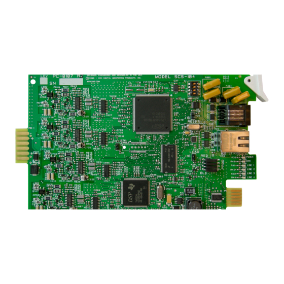
The SCS-104 provides four digital dialer (DD) lines and a network
connection for communication to DMP panels. Each card includes one
shielded eight-pin modular connector (J1) for the Ethernet network
connection. This allows the SCS-1R Receiver to accept alarm and
system messages over a network from DMP panels. Each card also
includes a non-shielded eight-pin modular connector (J3) that supports
up to four digital dialer lines, when connected to a standard RJ61 jack.
An optional PC software application, SCS-CTM Check-in Table Manager,
is available to backup the SCS-104 records of all supervised network
accounts for up to 32 different SCS-104 line cards.
is compatible with SCS-104 Version 100 or higher. For complete operation
information, refer to the SCS-CTM User's Guide (LT-0940). Contact DMP
Customer Service to purchase a copy of the SCS-CTM Check-in Table
Manager software.
Installing the SCS-104
Install the SCS-104 in any one of the SCS-1R positions
with the card puller in the up position. Connect the
10-position line card cable from the SCS-150 processor
card. The line card number is determined by the
processor card cable it is connected to.
THE LIGHT BROWN (PIN 1) WIRE OF THE FLAT CABLE
CONNECTOR MUST FACE UP ON THE LINE CARD.
Connecting the Phone Lines
Connect the phone line cable from the line card to
the customer supplied RJ61 jacks. Use a
standard 103J voice grade (analog) line.
Cables can be fed through the slot in
the receiver back plate. Maximum line
impedance is 100 Ohms.
The SCS-104 is registered with the FCC,
registration number CCKCN03BSCS-104;
Ringer Equivalence 0.3B.
Connecting the Network
Connect an IP network cable between
the J1 Ethernet connector on the front of
the line card and the network LAN/WAN
connection. Maximum line impedance is
100 Ohms.
The SCS-104 automatically communicates UDP or TCP with DMP panels and automatically communicates with
encrypted panels using 128-bit or 256-bit AES Encryption.
Note: 256-bit encrypted messages sent to the SCS-1R receiver from an XR550E Control Panel Version 104 or higher software
will only communicate with SCS-104 Line Cards with Version 102 or higher software.
Phone Line Monitor
The SCS-104 monitors incoming phone line voltage. During a loss of phone line voltage, the SCS-104 sends a Warning: Phone
Line Trouble message (System Message 153) to the host automation or LCD display.
Power Monitor LED
The green LED labeled PWR turns on when the power supply on the line card is working properly.
Inst alla tIon GUIDE
Model SCS-104 Line Card
The SCS-CTM program
Rack-Mounting
holes
SCS-104 Line Card
SCS-104 Line Cards
SCS-150 Receiver
Processor Card
Phone
J3
Line
Ethernet
J1
Red
Power
DTR
J8
Line 1
Line 2
Line 3
Black
Line 4
SCS-150 Network
Connection
Advertisement
Table of Contents

Related Manuals for DMP Electronics SCS-104


Summary of Contents for DMP Electronics SCS-104
- Page 1 SCS-104 Line Cards with Version 102 or higher software. Phone Line Monitor The SCS-104 monitors incoming phone line voltage. During a loss of phone line voltage, the SCS-104 sends a Warning: Phone Line Trouble message (System Message 153) to the host automation or LCD display.
- Page 2 COM port where the line card is connected. 7. Select Update. After the update is complete, remove the SCS-104 from the receiver and disconnect the 399 cable and remove the shorting clip from the LOAD header. Reinstall the Line Card to begin normal operation.
Need help?
Do you have a question about the SCS-104 and is the answer not in the manual?
Questions and answers