Table of Contents
Advertisement
Advertisement
Table of Contents
Troubleshooting

Related Manuals for Kongsberg cNODE Micro


Summary of Contents for Kongsberg cNODE Micro
- Page 1 Instruction Manual cNODE ® Micro...
- Page 3 Micro Transponder Instruction Manual 426351/A January 2018 © Kongsberg Maritime AS...
- Page 4 Kongsberg Maritime disclaims any responsibility for damage or injury caused by improper installation, use or maintenance of the equipment. Disclaimer Kongsberg Maritime AS endeavours to ensure that all information in this document is correct and fairly stated, but does not accept liability for any errors or omissions. Support information If you require maintenance or repair, contact your local dealer.
-
Page 5: Table Of Contents
Disconnecting the cNODE battery charger..............17 LED indicator status and troubleshooting................18 Powering up the transponder ...................19 Connecting the transponder to external power and responder signals......20 Connecting the cNODE Micro to the ROV ..............20 Disconnecting cNODE Micro from the ROV..............21 Powering up the TTC.......................21 Acoustic test........................21 Configuring the transponder ....................22... - Page 6 LED indicator status and troubleshooting................33 ILLUSTRATED SPARE PARTS CATALOGUE ......35 Micro 31-180 spare part....................36 cNODE Micro battery charger spare part ................36 On/off plug spare part ......................36 Pigtail cable spare part — Seacon 8F ................36 Transponder Test and Configuration unit (TTC30) spare part.........37 Test and configuration cable (TTC to Micro) spare part..........37...
-
Page 7: About This Manual
About this manual About this manual Observe this general information about the cNODE Micro Instruction Manual; its purpose and target audience. Purpose of manual The purpose of this instruction manual is to provide the descriptions and procedures required to install, operate and maintain the cNODE Micro. -
Page 8: Kongsberg Cnode Micro
Micro Instruction Manual Kongsberg cNODE Micro Topics Introduction, page 7 Model definition, page 7 General supply conditions, page 8 Support information, page 9 426351/A... -
Page 9: Introduction
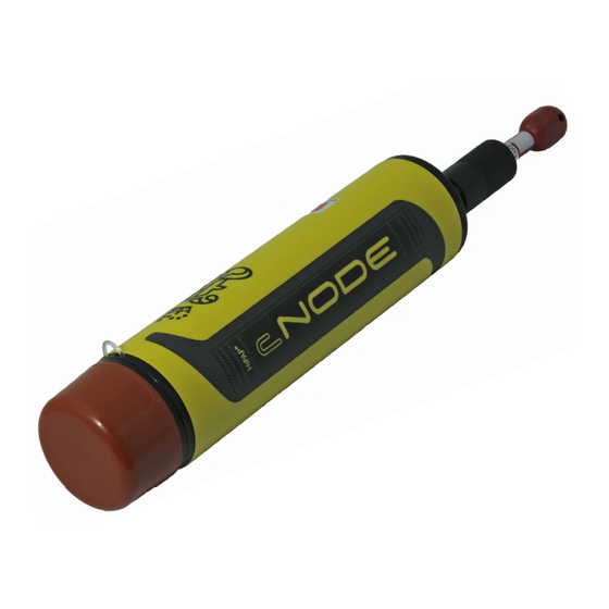
Introduction The cNODE® Micro transponder is a light and compact unit designed for use by divers and shallow water ROV’s. Operating on Kongsberg Cymbal digital acoustic protocols, the cNODE® Micro provides the optimal positioning performance with the Kongsberg range of SSBL systems, from µPAP® through to HiPAP®. -
Page 10: General Supply Conditions
• The period of time between commissioning and the final acceptance of the equipment by the end user or owner Unless other arrangements have been made in the contract, the Kongsberg cNODE Micro warranty period (as specified in the contract) begins when the acceptance documents have been signed. -
Page 11: Support Information
Kongsberg cNODE Micro Support information If you need support for your Kongsberg cNODE Micro you must contact Kongsberg Maritime AS. • : Kongsberg Maritime AS Company name • : Strandpromenaden 50, 3190 Horten, Norway Address • : +47 33 03 24 07 Telephone, 24h support •... -
Page 12: Main System Units
Micro Instruction Manual Main system units Topics cNODE Micro 31-180, page 11 Battery charger, page 11 TTC 30 (Transponder Test and Configuration unit), page 11 Test and configuration cable (TTC to Micro), page 11 Test and configuration cable (PC to Micro), page 12... -
Page 13: Cnode Micro 31-180
The TTC 30 unit is for on deck testing and configuration of the medium frequency Transponders. The TTC 30 can test all KONGSBERG Transponder channels, Cymbal and HPR 400. It can also test telemetry Transponders with internal and external sensors. -
Page 14: Test And Configuration Cable (Pc To Micro)
Micro Instruction Manual Test and configuration cable (PC to Micro) This cable connects the Micro to the PC. 426351/A... -
Page 15: General Acoustic Considerations
General acoustic considerations General acoustic considerations Acoustic range The depth rating should not be confused with acoustic range. The acoustic range is dependent on many factors, and some of the factors are outside control of the user. Vessel system The directivity and coverage area for the vessel system is different, depending on which system you are using. - Page 16 Micro Instruction Manual Sound velocity and ray bending Changes in sound velocity through the water column caused by changes in the water temperature and/or salinity can bend the acoustic signal and make it impossible to reach the vessel. 426351/A...
-
Page 17: Getting Started
Powering up the transponder, page 19 Connecting the transponder to external power and responder signals, page 20 Connecting the cNODE Micro to the ROV, page 20 Disconnecting cNODE Micro from the ROV, page 21 Powering up the TTC, page 21... -
Page 18: Charging The Battery (On-Deck)
Prerequisites Caution The cNODE Micro with battery must be climatised to a temperature between 10 and 40°C before charging. For on-deck charging use the cNODE Micro battery charger only. -
Page 19: Disconnecting The Cnode Battery Charger
Prerequisites Note Always disconnect the cNODE battery charger from the mains (110 or 220 VAC) before disconnecting the cNODE battery charger from the cNODE Micro. Procedure Disconnect the cNODE battery charger from mains (110 or 220 VAC). Disconnect the cNODE Micro from the cNODE battery charger. -
Page 20: Led Indicator Status And Troubleshooting
Micro and then • the charger or cNODE Micro might be faulty. Contact your local Kongsberg Maritime office if this to the mains (110 or 220 is the case. -
Page 21: Powering Up The Transponder
Getting started Powering up the transponder The transponder is designed for operation in water only. However, the transponder may be operated in air for test purposes over a short period of time. Procedure Connect the on/off plug to the end cap connector. Tighten the locking sleeve to the end cap connector. -
Page 22: Connecting The Transponder To External Power And Responder Signals
TTC30 (Transponder Test and Configuration) unit. Further requirements Pre deployment checks must be performed before the unit is installed/used. Connecting the cNODE Micro to the ROV It is very important to read the procedures before connecting the cNODE Micro to the ROV. Prerequisites Note Always connect the cNODE Micro to the ROV before turning on the power supply (24 VDC). -
Page 23: Disconnecting Cnode Micro From The Rov
Connect the cable between the cNODE Micro and the ROV. Turn on the power supply (24 VDC) to the cNODE Micro. Disconnecting cNODE Micro from the ROV It is very important to read the procedures before disconnecting the cNODE Micro from the ROV. Prerequisites... -
Page 24: Configuring The Transponder
Micro Instruction Manual Context To set use left/right arrows to choose power level and tap to confirm TTC POWER your selection. Procedure Connect the test transducer cable to the upper right connector. Place the Test transducer face to face with the transponder. -
Page 25: Cnode Micro Operation In Apos
Getting started cNODE Micro operation in APOS cNODE Micro only operates in Cymbal mode and uses the channels M01 - M56 for SSBL and M57 - M62 for LBL LIC. Channels such as B12 etc are not supported. Using existing versions of APOS... -
Page 26: Battery Status
Micro Instruction Manual To correct this, you need to delete the installed transponder and re-install it again with the original channel number. Battery status When reading battery status; “Unknown type” will be displayed and Battery size will show 0. -
Page 27: Pre-Deployment Checks
Getting started Pre-deployment checks Prior to deployment of the Transponder, it is important that the following checks are made to ensure correct operation. Procedure Make sure the retaining cord is in place. If the unit has been altered from the factory pre-sets, check that the unit is configured according to your requirements. - Page 28 Micro Instruction Manual Dry off the Transponder and make sure that there is no water around the On/off plug or the external connector. Turn the unit OFF by removing the On/off plug or disconnecting the external cable. Recharge the unit if it is deployed again and not stored.
-
Page 29: Cable Layout And Interconnections
Cable layout and interconnections Cable layout and interconnections Topics External connector, page 28 426351/A... -
Page 30: External Connector
Micro Instruction Manual External connector The external connector is for configuration, responder, on/off function and charging. Face view (male): Pin 1, 2 and 3 is for configuration. Pin 4 and 5 is for responder function. Pin 6 is for on/off function. -
Page 31: Operational Procedures
Operational procedures Operational procedures Once deployed the transponder is ready for operation. The transponder is operated from the HiPAP operator station APOS. • Refer to APOS online help for descriptions. 426351/A... -
Page 32: Maintenance
Micro Instruction Manual Maintenance All maintenance procedures you can do on the cNODE Micro are listed here. Topics Safety features, page 31 Charging the battery (on-deck), page 31 Disconnecting the cNODE battery charger, page 32 LED indicator status and troubleshooting, page 33... -
Page 33: Safety Features
Prerequisites Caution The cNODE Micro with battery must be climatised to a temperature between 10 and 40°C before charging. For on-deck charging use the cNODE Micro battery charger only. -
Page 34: Disconnecting The Cnode Battery Charger
Micro. Prerequisites Note Always disconnect the cNODE battery charger from the mains (110 or 220 VAC) before disconnecting the cNODE battery charger from the cNODE Micro. Procedure Disconnect the cNODE battery charger from mains (110 or 220 VAC). 426351/A... -
Page 35: Led Indicator Status And Troubleshooting
Maintenance Disconnect the cNODE Micro from the cNODE battery charger. LED indicator status and troubleshooting LED indicator What it means How to fix this Flashing green The battery is charging Constant green The battery is fully charged Flashing red The following might... - Page 36 Micro and then • the charger or cNODE Micro might be faulty. Contact your local Kongsberg Maritime office if this to the mains (110 or 220 is the case.
-
Page 37: Illustrated Spare Parts Catalogue
Topics Micro 31-180 spare part, page 36 cNODE Micro battery charger spare part, page 36 On/off plug spare part, page 36 Pigtail cable spare part — Seacon 8F, page 36 Transponder Test and Configuration unit (TTC30) spare part, page 37... -
Page 38: Micro 31-180 Spare Part
Micro Instruction Manual Micro 31-180 spare part • : cNODE Micro 31–180 Part name • : 424770 Part number cNODE Micro battery charger spare part • : cNODE Micro battery charger Part name • : 404199 Part number On/off plug spare part •... -
Page 39: Transponder Test And Configuration Unit (Ttc30) Spare Part
Illustrated spare parts catalogue Transponder Test and Configuration unit (TTC30) spare part • TTC 30 Part name: • 345775 Part number: Test and configuration cable (TTC to Micro) spare part • : Test and configuration cable, TTC to Micro Part name •... -
Page 40: Drawing File
Micro Instruction Manual Drawing file This chapter lists all the drawings needed for installation and maintenance. Topics Micro 31-180 outline drawing, page 39 426351/A... -
Page 41: Micro 31-180 Outline Drawing
Drawing file Micro 31-180 outline drawing Drawing 424722 426351/A... -
Page 42: Technical Specifications
Micro Instruction Manual Technical specifications Topics Environmental requirements, page 41 Performance specification, page 41 Power requirements, page 42 Weight and outline dimensions, page 42 426351/A... -
Page 43: Environmental Requirements
Technical specifications Environmental requirements These environmental specifications summarize the temperature and humidity requirements for the cNODE Micro. Micro 31–180 Operational temperature -5 to +55°C Storage temperature -30 to +70°C Aluminium transponders Housing material Anodised aluminium Housing coating Polyurethane Performance specification These performance specifications summarize the main functional and operational characteristics of the cNODE Micro. -
Page 44: Power Requirements
Micro Instruction Manual Power requirements These power characteristics summarize the supply power requirements for the cNODE Micro. Micro battery Battery type Li-Ion (LiFePO Nominal voltage 13.2 Vdc Nominal capacity 1100 mAh/14.52 Wh Battery charger Input voltage 110/230 Vac Micro external power... -
Page 45: Battery Safety
Section 15: Regulatory information, page 48 Section 16: Other information, page 49 Section 1: Identification : Battery pack (Li-ion) for cNODE Micro, part number 426688 Product name The battery is included in the following model: • cNODE Micro 31–180, part number 424770... -
Page 46: Section 2: Hazards Identification
Micro Instruction Manual : Strandpromenaden 50, 3190 Horten, Norway Address : +47 33 03 24 07 Telephone, 24 h support http://www.km.kongsberg.com Website http://www.km.kongsberg.com/support_hpr Support website km.support.hpr@kongsberg.com E-mail Section 2: Hazards identification The battery is not provided with any hazards identification. It is not classified as dangerous or hazardous with normal use. -
Page 47: Section 4: First Aid Measures
Battery safety • : A123 Systems Cell manufacturer • : 18650 Cell size • : 4S1P Battery configuration • : 1100 mAh/14.52 Wh Nominal capacity • : 1.33 g Equivalent Lithuim content • : UN 38.3 Certification Note For additional information about these cells, see the safety data sheet provided by the cell manufacturer. -
Page 48: Section 6: Accidental Release Measures
Micro Instruction Manual The interaction with water or water vapor and exposed lithium hexafluorophosphate (Li PF6) may result in the generation of hydrogen and hydrogen fluoride (HF) gas. Contact with battery electrolyte may be irritating to skin, eyes and mucous membranes. Fire will produce irritating, corrosive and/or toxic gases. -
Page 49: Section 9: Physical And Chemical Properties
Battery safety Personal protective equipment for damaged battery should include chemical resistant gloves and safety glasses. Use positive pressure self–contained breathing apparatus (SCBA) if batteries or transponders are involved in a fire. Section 9: Physical and chemical properties The battery is solid with a firm and hard appearance. No chemicals are exposed during normal use and transportation. -
Page 50: Section 14: Transport Information
ICAO/IATA packing instructions 967 Section II; Cells or batteries installed in equipment. The cNODE Micro transponder unit must be shipped in accordance with the prevailing national regulations; UN No. 3481, Miscellaneous (Lithium Ion batteries included in equipment). -
Page 51: Section 16: Other Information
Battery safety Section 16: Other information The battery cell manufacturer’s safety data sheet is available on the following internet address: • : www.a123systems.com A123 Systems 426351/A... - Page 52 ........7 unpacking ..........8 cNODE Micro getting started description ..........7 connecting the cNODE Micro to the ROV ... 20 cNODE Micro 31-180 connecting the pigtail to the external power description ..........11 supply ............ 20 cNODE Micro 31–180 deployment ..........
- Page 53 35 safety features ..........31 main system units ........... 10 pressure relief valve ........31 maintenance ..........30 setting up a cNODE Micro in APOS..... 23 Transponder ..........30 spare part manual cNODE Micro 31–180 ........36 purpose ............. 5 cNODE Micro battery charger ......
- Page 54 Micro Instruction Manual unpacking general supply conditions........ 8 using existing versions of APOS ......23 weight and outline dimensions......42 426351/A...
- Page 56 ©2018 Kongsberg Maritime...
Need help?
Do you have a question about the cNODE Micro and is the answer not in the manual?
Questions and answers