Table of Contents
Advertisement
Operation - Repair
™
RS
Gun and
Cutter
For use with polyester resin and gel-coat.
For professional use only.
Important Safety Instructions
Read all warnings and instructions in this
manual. Save these instructions.
See page 3 for model information, including maxi-
mum working pressure.
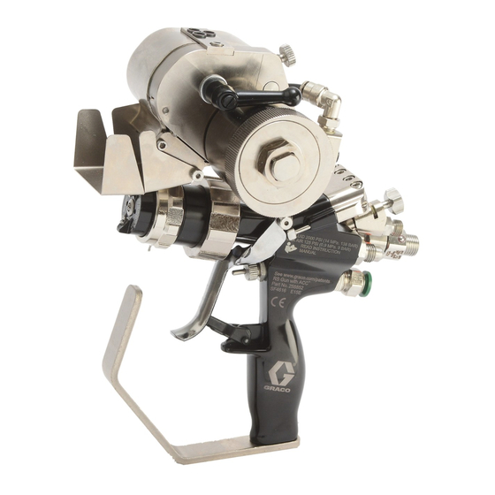
External Mix Chop Gun with Cutter shown
3A0232ZAA
EN
II 2 G Ex h T6 Gb
Advertisement
Table of Contents

Related Manuals for Graco RS


Summary of Contents for Graco RS
- Page 1 Operation - Repair ™ Gun and Cutter 3A0232ZAA For use with polyester resin and gel-coat. For professional use only. Important Safety Instructions Read all warnings and instructions in this manual. Save these instructions. See page 3 for model information, including maxi- mum working pressure.
-
Page 2: Table Of Contents
Graco Standard Warranty ....66 Graco Information ......66... -
Page 3: Models
Part Description 3A1226 Universal Adapter Kit 257754 Instructions 3A2054 Indy or Formula Adapter Kit 125797 Instructions 3A2079 LPA2 Adapter Kit 125843 Instructions 332574 RS Gun Cutter Assemblies Operation-Repair 334010 RS Gun External Mix Chopper Extension Kit 24V096 Instructions 3A0232ZAA... -
Page 4: Warnings
Warnings Warnings The following warnings are for the setup, use, grounding, maintenance, and repair of this equipment. The exclama- tion point symbol alerts you to a general warning and the hazard symbols refer to procedure-specific risks. When these symbols appear in the body of this manual, refer back to these Warnings. Product-specific hazard symbols and warnings not covered in this section may appear throughout the body of this manual where applicable. - Page 5 Warnings WARNING TOXIC FLUID OR FUMES HAZARD Toxic fluids or fumes can cause serious injury or death if splashed in the eyes or on skin, inhaled, or swallowed. • Read MSDSs to know the specific hazards of the fluids you are using. •...
-
Page 6: Important Two-Component Information
Important Two-Component Information Important Two-Component Information Material Self-ignition Some materials may become self-igniting if applied too thickly. Read material manufacturer’s warnings and material MSDS. Keep Components A and B Separate Cross-contamination can result in cured material in fluid lines which could cause serious injury or damage equipment. -
Page 7: Important Methyl Ethyl Ketone Peroxide (Mekp) Safety Information
Use only original equipment or equivalent parts ing and disposal. from Graco in the catalyst system (i.e.: hoses, fittings, Workers must be thoroughly informed of the hazards etc.) because a hazardous chemical reaction may that may result from improper handling of MEKP, espe- result between substituted parts and MEKP. - Page 8 MSDS to know specific hazards and precautions. (Graco recom- mends that clean-up solvents be nonflammable.) NOTE: Graco recommends that you consult OSHA Sec- tions 1910.94, 1910.106, 1910.107 and NFPA No. 33, Chapter 16,17, and NFPA No. 91 for further guidance.
- Page 9 Important Methyl Ethyl Ketone Peroxide (MEKP) Safety Information 3A0232ZAA...
-
Page 10: Component Identification
Component Identification Component Identification External Mix Gel Gun, 258840 258840_3A0232_1g Key: Trigger Clamp Assembly Spray Tip Gun Mount Trigger guard Front Head Locking Ring Trigger Air Cap Retaining Ring Trigger lock External Mix Aircap Handle External Mix Front Head Actuator Pin 3A0232ZAA... -
Page 11: Internal Mix Gel Gun, 258853
Component Identification Internal Mix Gel Gun, 258853 NOTE: On internal mix guns, the tip rotates to allow a vertical or horizontal spray pattern. ti21003a Key: Trigger Clamp Assembly Spray Tip Gun Mount Trigger guard Front Head Locking Ring Trigger Air Cap Retaining Ring Trigger lock Internal Mix Aircap Handle... -
Page 12: Internal Mix Chop Gun, 258854
Component Identification Internal Mix Chop Gun, 258854 NOTE: On internal mix guns, the tip rotates to allow ver- tical or horizontal spray pattern. ti21004b Key: Trigger Clamp Assembly Spray Tip Cutter Mount Trigger guard Front Head Locking Ring Trigger Air Cap Retaining Ring Trigger lock Internal Mix Aircap Handle... -
Page 13: Internal Mix Chop Gun, 24P436, High Flow, Carbide Seat
Component Identification Internal Mix Chop Gun, 24P436, High Flow, Carbide Seat NOTE: On internal mix guns, the tip rotates to allow ver- tical or horizontal spray pattern. ti21005b Key: Trigger Clamp Assembly Spray Tip Cutter Mount Trigger guard Front Head Locking Ring Trigger Air Cap Retaining Ring Trigger lock... -
Page 14: External Mix Chop Gun, 258852
Component Identification External Mix Chop Gun, 258852 ti21006b Key: Trigger Clamp Assembly Spray Tip Cutter Mount Trigger guard Front Head Locking Ring Trigger Air Cap Retaining Ring Trigger lock External Mix Aircap Handle External Mix Front Head Actuator Pin 3A0232ZAA... -
Page 15: Theory Of Operation
NOTE: Grounding wire and clamp assembly 17440-00 Internal Mix is included with Graco FRP proportioner. If using a dif- ferent proportioner that does not come with a ground- The material and catalyst pass through an internal static ing wire and clamp assembly, order 17440-00 or mixer where they mix. -
Page 16: Setup
7. For guns with cutters, insert glass strands into feed. 8. For guns with cutters, adjust anvil to blade ten- sion. Refer to RS Gun Cutter Assemblies Opera- tion-Repair for part identification: a. Release lockdown. b. Adjust tension knob as desired. - Page 17 Setup 10. Adjust AAC pressure on proportioner. 11. Perform test spray. Adjust system and gun settings as necessary to get desired results. 258840_3A0232_2g External Mix Internal Mix Chop Internal Mix Gel Fitting Size Atomized Air Air Assist Contain- Plugged 1/4 tube (Catalyst) ment (AAC) Resin Inlet...
-
Page 18: Startup
Startup Startup 1. Inspect o-rings on housings. Replace as needed. See F . 8. Housing O-rings 258840_3A0232_3g 2. Prime the system as required. NOTICE Gun damage can occur when the system is primed with the front head installed. To avoid damage, only prime the system with the front head removed. -
Page 19: Operation
Operation Operation Adjust AAC If the spray pattern is not even, the AAC air pressure High-pressure fluid from gun, hose leaks, or ruptured may need to be adjusted. For all guns, the AAC air pres- components will pierce skin. This may look like just a sure is set at the system. -
Page 20: Pressure Relief Procedure
Pressure Relief Procedure Pressure Relief Procedure 1. Shutdown proportioner. 2. Relieve proportioner pressure. See proportioner manual. 3. Engage gun trigger lock. 4. Close the bleed-type master air valve. 5. Disengage the trigger lock. 6. Hold a metal part of the gun firmly to a grounded metal pail. -
Page 21: Shutdown
Shutdown Shutdown 4. For internal mix guns, remove mixing element. Daily Shutdown NOTICE Failure to perform this procedure correctly and accord- ing to the prescribed schedule can result in poor mix- ti17896b ing, fluid leaking, and cured material in or on the gun. 1. - Page 22 Shutdown 6. Immerse front head, front cap, and the mixing ele- 8. Rinse excess resin from the resin port. ment (internal mix guns only) in solvent. Use a sealed container to prevent solvent evaporation. NOTICE Immersing the cutter assembly in solvent will damage it and void the warranty.
-
Page 23: Long-Term Shutdown
Shutdown Long-Term Shutdown NOTICE Failure to clean the surface between the trigger clamp If gun will be unused for at least one week, perform this and the gun body can lead to material buildup prevent- long-term shutdown procedure. ing the clamp from seating properly resulting in mate- rial leakage from the front of the gun. -
Page 24: Maintenance
Maintenance Maintenance Flush System NOTE: • Flush before changing colors, before fluid can dry in the equipment, before storing, and before repairing equipment. • Flush at the lowest pressure possible. Check con- nectors for leaks and tighten as necessary. • Flush with a fluid that is compatible with the fluid being dispensed and the equipment wetted parts. -
Page 25: Troubleshooting
Troubleshooting Troubleshooting See the troubleshooting procedures beginning on page 29 for additional troubleshooting help. Problem Cause Solution Catalyst leaking Trigger clamp assembly slipped See Fluid Leaking from Front of Gun on page 29. Catalyst hose loose Inspect and tighten Catalyst fitting loose Inspect and tighten Locking ring loose Clean and tighten... - Page 26 Troubleshooting Problem Cause Solution Gun does not fully Trigger clamp not opening properly Perform Adjust Trigger Clamp procedure on actuate when trig- page 29 gered Safety lock engaged Disengage safety lock Trigger clamp pins bent Inspect and replace if necessary Cutter air valve stuck Inspect and replace if necessary Overspray on trigger clamp pins...
- Page 27 Troubleshooting Problem Cause Solution Catalyst is present No resin Check material fluid level but no resin Trigger clamp out of phase 1) Adjust Trigger Clamp, page 29 2) Adjust Actuator Pin Adjustment Screws, page 31 Catalyst pump in bypass Turn on and make ready to spray Actuator adjustment screw missing Replace then perform Adjust Actuator Pin Adjustment Screws, page 31...
- Page 28 Troubleshooting Problem Cause Solution No solvent Not enough solvent pressure Increase solvent pressure to the recommended range of 80-100 psi (550-700 kPa, 5.5-7.0 bar). No fluid in pressure pot Refill pressure pot Output valve closed Open output valve Check valve stuck closed Increase pressure in pressure pot Material check valve plugged Clean and replace as needed...
-
Page 29: Fluid Leaking From Front Of Gun
Troubleshooting Fluid Leaking from Front of Gun Adjust Trigger Clamp To prevent skin injection, never use a gun that has a To prevent skin injection, never use a gun that has a resin and/or catalyst leakage. resin and/or catalyst leakage. Perform this procedure to find the source of the leakage NOTICE and to stop the leak. -
Page 30: Fluid Leaking From Under Trigger Clamp Assembly
Troubleshooting Fluid Leaking from Under c. Discard the o-ring (909) if wear or damage is found. Trigger Clamp Assembly d. Reassemble the needle assembly. 1. Follow Pressure Relief Procedure, page 20. 2. Remove trigger clamp assembly (A). e. Install the needle assembly into the gun. See Adjust Trigger Clamp on page 29 to install and adjust the trigger clamp. -
Page 31: Adjust Actuator Pin Adjustment Screws
Troubleshooting Adjust Actuator Pin Adjustment 7. Adjust each screw until the actuator pin just begins to touch the trigger. This can be verified by the trig- Screws ger just beginning to lift off of the trigger lock. 8. Back each screw out 1/2 turn. 9. -
Page 32: Repair
Repair Repair Remove Hardened Material from Internal Mix Front Head 816* 806* 812* 813* * Parts shown are not available on internal mix, high flow front . 13 Perform this procedure when the internal mix diffuser assembly is filled with cured material. When this hap- pens, the diffuser assembly must be drilled out. - Page 33 Repair 7. For standard 1/4 in. mixers, use a 0.152 in. drill in 12. Install check valve (812) and new spring (813) into the diffuser assembly outlet to remove hardened the seat then install cap (806). See F . 18 for orien- material.
-
Page 34: Replace Internal Mix Element
Repair Replace Internal Mix Element 816* 806* * Parts shown are not 812* available on internal mix, high flow front 813* . 17 See internal mix front head parts list on page 50 for 8. Install check valve (812) and spring (813) into the available kits. -
Page 35: Replace External Mix Check Valve
Repair Replace External Mix Check Valve and O-Rings . 19 See Front Head Assemblies beginning on page 49 for 10. Install air cap onto head and tighten retaining available kits. ring (710). 1. Perform Pressure Relief Procedure, page 20. NOTICE To prevent distorting the end of the cap (706), do 2. -
Page 36: Replace Material Needle Assembly
Repair Replace Material Needle Replace Center Needle Assembly Assembly NOTE: The material needle assemblies are the two side 1. Follow Pressure Relief Procedure, page 20. needles (105) in the rear of the gun. See page 38. 2. Loosen four screws (113) then remove trigger clamp assembly (111). -
Page 37: Replace Needle Packing
Repair Replace Needle Packing NOTE: The needle packing is the seal (904) inside the needle assembly (105). See pages 38 and 52. NOTICE Needles bend easily. To prevent bending and damag- ing the needles, be careful when using wrenches to remove the needle packings. -
Page 38: Parts
Parts Parts External Mix Gel Gun, 258840 115b 115a 116a ti21015a 3A0232ZAA... - Page 39 24M833 P OPTIONAL - RETAINER, seat, note to physician needle valve, resin, carbide CST521 TIP, spray, 521 104† 24D201 RETAINER, seat, catalyst 158 16P319 LABEL, quick start, RS gun 105** 24E417 NEEDLE, assembly 295662 PLUG, pipe 106 16C101 NEEDLE, aac 189018 SWIVEL 107...
-
Page 40: Internal Mix Gel Gun, 258853
Parts Internal Mix Gel Gun, 258853 When converting an Internal Gel gun to an Internal Chop gun, replace top housing with 24M045. 215b 215a 217b 216a 217a ti21016a 3A0232ZAA... - Page 41 222385 TAG, skin injection warning and 204† 24D201 RETAINER, seat, catalyst note to physician 205** 24E417 NEEDLE, assembly 258 16P319 LABEL, quick start, RS Gun GC2241 SCREW, set 295662 PLUG, pipe 211 16C098 CLAMP, trigger, top 189018 SWIVEL 212 16C099 CLAMP, trigger, bottom Parts included in Solvent/AAC assembly kit 24E415.
-
Page 42: External Mix Chop Gun With Cutter, 258970
External Mix Chop Gun with Cutter, 258970 Ref Part Description 301 258852 GUN, external mix, chop 302 24E512 CUTTER ASSEMBLY, external mix 303 16P320 LABEL, quick start, RS gun Internal Mix Chop Gun with Cutter, 258971 Ref Part Description 401 258854 GUN, internal mix, chop... -
Page 43: Chop Guns
Parts Chop Guns External Mix Chop Gun, 258852 516a 515b 516a1 515a ti17943b 3A0232ZAA... - Page 44 Parts Internal Mix Chop Gun, 258854 516a1 515b 516a 515a 516b 516b2 516b1 ti21018a 3A0232ZAA...
- Page 45 Parts High Flow Internal Mix Chop Gun, 24P436 516a1 516a 515b 515a 516b 516b1 516b2 ti21019a 3A0232ZAA...
- Page 46 Parts External Mix, Internal Mix, and Internal Mix High Flow Chop Gun Parts Quantity Part Description 258852 258854 24P436 199360 DOCUMENT, declaration 24N711 HANDLE, gun 502† 24E428 SEAL, needle, seat (pack of 6) 16C104‡ RETAINER, seat, needle valve, resin 24M833‡ RETAINER, seat, needle valve, resin, carbide 24D201 RETAINER, seat, catalyst 505**...
- Page 47 Parts Quantity Part Description 258852 258854 24P436 538 16C108 FITTING, catalyst hose 539 16C103 BODY, chopper mount 540 16C120 ADAPTER, chopper rotation 541 16F501 TUBE, air pivot 24F997 TUBE, air pivot 542 24E433 PACKING, o-ring (pack of 6) 543 123909 SCREW, cap, socket head 239663 SWIVEL, straight...
- Page 48 Parts Cutter Adapter Kits External Mix Cutter Adapter Kit, 24E422 Internal Mix Cutter Adapter Kit, 24G832 Internal Mix Adapter External Mix Adapter ti21020a These kits provide replacement parts for the cutter adapter. To convert an external mix gel gun to an external mix chop gun, see External Mix Gel Gun to Chop Gun Conversion on page 55.
-
Page 49: Front Head Assemblies
Parts Front Head Assemblies External Mix Horizontal Spray Pattern Front Head, 24E426 External Mix Vertical Spray Pattern Front Head, 24E427 708a 708a Part Description 262696 HEAD, spray, external mix 16C220 RING, locking 703* 16C489 SEAL, tip, external mix 704*† M72843 BALL, sst 705*†... - Page 50 Parts Internal Mix Gel Front Head, 24G615 Internal Mix Chop Front Head, 24E442 NOTICE There is a half-moon pin pressed into the front head (801) behind the diffuser assembly (803). Do not attempt to remove this pin. Removal will result in poor mixing.
- Page 51 Parts Internal Mix, High Flow Chop Front Head, 24P562 NOTICE There is a half-moon pin pressed into the front head (801) behind the diffuser assembly (803). Do not attempt to remove this pin. Removal will result in poor mixing. Parts included in retaining ring kit 24H274. Part Description ...
-
Page 52: Needle Assembly, 24E417
Parts Needle Assembly, 24E417 ti16592a Beveled edge must face rear of needle Part Description 123634 SPRING, needle assembly 16C080 HOUSING, needle packing 903* 16C081 RETAINER, packing 904* 24H279 PACKING, disk (pack of 6) 905* 16C083 RETAINER, packing 16C086 NUT, packing material 907* 16C087 CLIP, retainer 24C780 NEEDLE, assembly... -
Page 53: O-Ring Identification
Parts O-ring Identification The following illustration shows all available o-rings at actual size. See the respective illustration in the Parts section beginning on page 38 for part references and locations. White (PTFE) O-rings 131, 231, 531 713, 811 Black (FKM) O-rings 110, 510 109, 509 119, 241... -
Page 54: Accessories
125797 Casting Nozzle Adapter Kit, 16T707 Ideal for mounting an RS gun in place of an INDy or For- mula gun. Kit includes the necessary items to connect Ideal for casting nozzle applications. the RS gun to the connections used by INDy and For- mula guns. -
Page 55: Aac Regulators
Accessories AAC Regulators External Mix Gel Gun to Chop Gun Conversion 24G571 - for use with internal mix gel guns 22632-00 - for use with internal mix chop guns To convert your external mix gel gun to a chop gun, pur- chase and install the following kits: 1001 •... -
Page 56: Pressure Fed Roller Adapter Kit, 16T708
Accessories Pressure Fed Roller Adapter Kit, Tools 16T708 Hex Keys for Guns, 24F007 Ideal for pressure feed rolling with the RS gun. Includes: Application Specific: • One 3/32 in. hex key • One 9/64 in. hex key Part Description •... - Page 57 Accessories 3A0232ZAA...
-
Page 58: Impingement Spray Tips
CSTS85 CSTS36* CSTS46* CSTS56* CSTS66* CSTS76* CSTS86* CSTS37* CSTS47* CSTS57* CSTS67* CSTS77 CSTS87 CSTS58 CSTS68 CSTS78 CSTS88 *Available in tooling steel RS Gun ® GlasCraft Angled Hole Straight Hole Impingement Spray Part No. Ref Diameter Diameter Pattern Width Tip Part No. †... - Page 59 Accessories RS Gun ® GlasCraft Angled Hole Straight Hole Impingement Spray Part No. Ref Diameter Diameter Pattern Width Tip Part No. † CSTS61 0.018 (0.46) 0.012 (0.30) 12 (300) 23005-J1 CSTS62 0.021 (0.53) 0.014 (0.36) 12 (300) 23005-J2 CSTS63 0.036 (0.91)
- Page 60 Accessories 5th digit = pattern width code. Double number to get pattern size at 18 in. (450 mm). Example: 5 = 10 in. (250 mm) pattern at 18 in. (450 mm) distance to target. 6th digit = orifice size code. Number roughly matches a 0.010 in. (0.254 mm) increment of the angled hole dia. Exp: 5 = 0.052 in.
-
Page 61: Airless Spray Tips
CST643 CST351 CST451 CST551 CST651 CST461 CST561 CST661 CST471 CST571 CST671 RS Gun Airless Spray Tip GlasCraft Tip Part No. † Orifice Diameter Pattern Width Part No. Ref CST215 0.015 in. (0.38 mm) 4-6 in. (100-150 mm) LPA2-147-1525 CST217 0.017 (0.43) - Page 62 Accessories RS Gun Airless Spray Tip GlasCraft Tip Part No. † Orifice Diameter Pattern Width Part No. Ref CST421 0.021 (0.53) 8-10 (200-250) LPA2-147-2140 CST423 0.023 (0.58) 8-10 (200-250) LPA2-147-2340 CST425 0.025 (0.64) 8-10 (200-250) CST427 0.027 (0.69) 8-10 (200-250)
-
Page 63: Technical Data
Technical Data Technical Data See Models on page 3 for more information. RS Gun and Cutter Metric Maximum Fluid Working Pressure Internal Mix 258853 2000 psi 138 bar, 14 MPa 258854 2000 psi 138 bar, 14 MPa 258971 2000 psi... - Page 64 Technical Data RS Gun and Cutter Metric Weight 258853 2.32 lb 1.05 kg 258854 2.46 lb 1.12 kg 258840 2.08 lb 0.94 kg 258852 2.33 lb 1.04 kg Sound Power Measured per ISO-3746 258853 98.1 dB (A) at 60 psig 258854 90.6 dB(A) at 50 psig...
-
Page 65: Dimensions
Technical Data Dimensions 258840_3A0232_1g Dimensions; in. (mm) External, Gel Internal, Gel Internal, Chop External, Chop A, Height 7.37 (187) 7.37 (187) 10.29 (261.4) 10.29 (261.4) B, Length 7.60 (193) 9.2 (234) 9.2 (234) 7.60 (193) C, Width 2.36 (59.9) 2.36 (59.9) 5.07 (129) 5.07 (129) 3A0232ZAA... -
Page 66: Graco Standard Warranty
With the exception of any special, extended, or limited warranty published by Graco, Graco will, for a period of twelve months from the date of sale, repair or replace any part of the equipment determined by Graco to be defective.
Need help?
Do you have a question about the RS and is the answer not in the manual?
Questions and answers