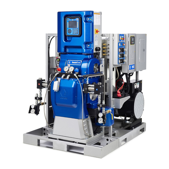
Graco Reactor 2 H-30 Operation
Hydraulic proportioning systems
Hide thumbs
Also See for Reactor 2 H-30:
- Repair parts (110 pages) ,
- Repair manual (102 pages) ,
- Manual (102 pages)
Table of Contents
Advertisement
Operation
Reactor® 2 2 2 Hydraulic
Reactor®
Reactor®
Systems
Systems
Systems
Hydraulic, heated,
heated, plural
plural component
Hydraulic,
Hydraulic,
heated,
plural
Not for
for outdoor
outdoor use.
use. For
For professional
Not
Not
for
outdoor
use.
For
Not approved
approved for
for use
use in in in explosive
Not
Not
approved
for
use
Important
Important Safety
Important
Safety Instructions
Safety
Read all warnings and instructions in this manual. Save these
instructions.
For model information, see page 9.
Hydraulic Proportioning
Proportioning
Hydraulic
Proportioning
component proportioner
proportioner for
component
proportioner
professional use
use only.
only.
professional
use
only.
explosive atmospheres
atmospheres or or or hazardous
explosive
atmospheres
Instructions
Instructions
PROVEN QUALITY. LEADING TECHNOLOGY.
for spraying
spraying polyurethane
polyurethane foam
for
spraying
polyurethane
hazardous (classified)
(classified) locations.
hazardous
(classified)
334945J
foam and
and polyurea
polyurea coatings.
foam
and
polyurea
locations.
locations.
EN
coatings.
coatings.
Advertisement
Table of Contents

Related Manuals for Graco Reactor 2 H-30


Summary of Contents for Graco Reactor 2 H-30
- Page 1 Operation Reactor® 2 2 2 Hydraulic Hydraulic Proportioning Proportioning Reactor® Reactor® Hydraulic Proportioning Systems Systems Systems 334945J Hydraulic, heated, heated, plural plural component component proportioner proportioner for for spraying spraying polyurethane polyurethane foam foam and and polyurea polyurea coatings. coatings. Hydraulic, Hydraulic, heated,...
-
Page 2: Table Of Contents
Dimensions ............74 System 2 ............. 38 Notes ............... 75 System 3 ............. 38 System 4 ............. 38 Technical Specifications........76 Recipes............39 California Proposition 65 ........77 Cellular Screen ..........39 Run Mode ........... 40 Graco Extended Warranty ........78 334945J... -
Page 3: Warnings
Warnings Warnings Warnings Warnings The following warnings are for the setup, use, grounding, maintenance, and repair of this equipment. The exclamation point symbol alerts you to a general warning and the hazard symbols refer to procedure-specific risks. When these symbols appear in the body of this manual or on warning labels, refer back to these Warnings. - Page 4 Warnings WARNING WARNING WARNING SKIN SKIN SKIN INJECTION INJECTION INJECTION HAZARD HAZARD HAZARD High-pressure fluid from dispensing device, hose leaks, or ruptured components will pierce skin. This may look like just a cut, but it is a serious injury that can result in amputation. Get immediate surgical surgical treatment.
- Page 5 Warnings WARNING WARNING WARNING THERMAL THERMAL THERMAL EXPANSION EXPANSION HAZARD EXPANSION HAZARD HAZARD Fluids subjected to heat in confined spaces, including hoses, can create a rapid rise in pressure due to the thermal expansion. Over-pressurization can result in equipment rupture and serious injury.
- Page 6 Warnings WARNING WARNING WARNING EQUIPMENT EQUIPMENT EQUIPMENT MISUSE MISUSE HAZARD MISUSE HAZARD HAZARD Misuse can cause death or serious injury. • Do not operate the unit when fatigued or under the influence of drugs or alcohol. • Do not exceed the maximum working pressure or temperature rating of the lowest rated system component.
-
Page 7: Important Isocyanate Information
Important Isocyanate Information Important Isocyanate Isocyanate Information Information Important Important Isocyanate Information Isocyanates (ISO) are catalysts used in two component materials. Isocyanate Conditions Conditions Isocyanate Isocyanate Conditions Spraying or dispensing fluids that contain isocyanates creates potentially harmful mists, vapors, and atomized particulates. - Page 8 Important Isocyanate Information Material Self Self - - - Ignition Ignition Moisture Sensitivity Sensitivity of of of Isocyanates Isocyanates Material Material Self Ignition Moisture Moisture Sensitivity Isocyanates Exposure to moisture (such as humidity) will cause ISO to partially cure, forming small, hard, abrasive crystals that become suspended in the fluid.
-
Page 9: Models
Models Models Models Models Reactor Reactor Reactor 2 2 2 H H H - - - 30 30 and and H H H - - - 30 30 Elite Elite Elite H H H - - - 30 30 Model Model H H H - - - 30 30 Elite... - Page 10 Models Reactor 2 2 2 H H H - - - 40 40 and and H H H - - - 40 40 Elite, Elite, Reactor Reactor Elite, 200–240V 200–240V 200–240V H H H - - - 40 40 Model Model Model H H H - - - 40...
- Page 11 Models Reactor 2 2 2 H H H - - - 40 40 and and H H H - - - 40 40 Elite, Elite, Reactor Reactor Elite, 350–415V (Continued) (Continued) 350–415V 350–415V (Continued) H H H - - - 40 40 Model Model Model...
- Page 12 Models Reactor 2 2 2 H H H - - - 50 50 and and H H H - - - 50 50 Elite Elite Reactor Reactor Elite H H H - - - 50 50 Model Model H H H - - - 50 50 Elite Elite Model Model...
- Page 13 Models Reactor 2 2 2 H H H - - - XP2 XP2 and and H H H - - - XP2 XP2 Elite Elite Reactor Reactor Elite H H H - - - XP2 XP2 Model Model Model H H H - - - XP2 XP2 Elite Elite Elite Model...
- Page 14 Models Reactor 2 2 2 H H H - - - XP3 XP3 and and H H H - - - XP3 XP3 Elite Elite Reactor Reactor Elite H H H - - - XP3 XP3 Model Model Model H H H - - - XP3 XP3 Elite Elite Elite Model...
-
Page 15: Accessories
Integrated PowerStation, Tier 4 Final, no air *979201 Integrated PowerStation, Tier 4 Final, 20 cfm *979202 Integrated PowerStation, Tier 4 Final, 35 cfm NOTE: The Integrated PowerStation is only * NOTE: NOTE: compatible with Reactor 2 H-30 and H-XP2 proportioning systems. 334945J... -
Page 16: Supplied Manuals
3A3009 Inlet Sensor Kit, Instructions-Parts 3A1907 Remote Display Module Kit, Instructions-Parts 332735 Air Manifold Kit, Instructions-Parts 3A3010 Caster Kit, Instructions-Parts 3A6738 Ratio Monitoring Retrofit Kit, Instructions-Parts 3A3084 Elite Kit, Instructions-Parts 3A6335 Integrated PowerStation, Instructions Manuals are available at www.graco.com. 334945J... -
Page 17: Typical Installation, Without Circulation
Typical Installation, without circulation Typical Installation, Installation, without without circulation circulation Typical Typical Installation, without circulation Figure 1 * Shown exposed for clarity. Wrap with tape during operation. Reactor Proportioner Fluid Supply Lines Heated Hose Feed Pumps Fluid Temperature Sensor (FTS) Agitator Heated Whip Hose Desiccant Dryer... -
Page 18: Typical Installation, With System Fluid Manifold To Drum Circulation
Typical Installation, with system fluid manifold to drum circulation Typical Installation, Installation, with with system system fluid fluid manifold manifold to to to drum drum Typical Typical Installation, with system fluid manifold drum circulation circulation circulation Figure 2 * Shown exposed for clarity. Wrap with tape during operation. Reactor Proportioner Fluid Supply Lines Heated Hose... -
Page 19: Typical Installation, With Gun Fluid Manifold To Drum Circulation
Typical Installation, with gun fluid manifold to drum circulation Typical Installation, Installation, with with gun gun fluid fluid manifold manifold to to to drum drum Typical Typical Installation, with fluid manifold drum circulation circulation circulation Figure 3 * Shown exposed for clarity. Wrap with tape during operation. Reactor Proportioner Fluid Supply Lines Heated Hose... -
Page 20: Component Identification
Component Identification Component Identification Identification Component Component Identification Figure 4 334945J... - Page 21 Component Identification ISO Side Pressure Relief Outlet RES Side Pump RES Side Pressure Relief Outlet Red Stop Button Advanced Display Module (ADM) Remote Display Module (optional) Electrical Cord Strain Relief ISO Side PRESSURE RELIEF/SPRAY Valve Electric Motor (behind shroud) RES Side PRESSURE RELIEF/SPRAY Valve ISO Side Fluid Manifold Inlet ISO Side Pressure Transducer (behind...
-
Page 22: Advanced Display Module (Adm)
Advanced Display Module (ADM) Advanced Display Display Module Module (ADM) (ADM) Advanced Advanced Display Module (ADM) Table 1 1 1 : : : ADM ADM Keys Keys and and Indicators Indicators The ADM display shows graphical and text Table Table Keys Indicators information related to setup and spray operations. - Page 23 Advanced Display Module (ADM) Figure 6 ADM Back View Flat Panel Mount (VESA 100) Model and Serial Number USB Port and Status LEDs CAN Communication Cable Connection Module Status LEDs Accessory Cable Connection Token Access Cover Backup Battery Access Cover Table Table 2 2 2 ADM Table...
-
Page 24: Adm Display Details
Advanced Display Module (ADM) ADM Display Display Details Details Display Details System Mode Mode System System Mode The current system mode is displayed at the lower Power Up Up Screen Screen Power Power Screen left of the menu bar. System System Errors System Errors... - Page 25 Advanced Display Module (ADM) Icons Icons Icons Icon Function Icon Function Icon Icon Function Function Icon Icon Function Function Component A Alarm. Troubleshoot Errors, page 67 for more information. Component B Pump Moving Left Pump Moving Right Estimated Supply Material Hose Temperature in Hose Pressure FTS Mode...
- Page 26 Advanced Display Module (ADM) Soft Keys Keys Soft Soft Keys Icons next to the soft keys indicate which mode or Icon Function Icon Icon Function Function action is associated with each soft key. Soft keys Toggle between upper-case, lower-case, that do not have an icon next to them are not active and numbers and special characters.
-
Page 27: Electrical Enclosure
Electrical Enclosure Electrical Enclosure Enclosure Electrical Electrical Enclosure H-40, H-40, H-50, H-40, H-50, H-XP3 H-50, H-XP3 H-XP3 H-30, H-30, H-30, H-XP2 H-XP2 H-XP2 AAA Temperature Control Module (TCM) AAB Hydraulic Control Module (HCM) AAC Enclosure Fan(s) AAD Wiring Terminal Blocks (H-30/H-XP2 only) AAE Power Supply AAF Sacrificial Surge Protector (SSP) AAG Hose Breaker... -
Page 28: Hydraulic Control Module (Hcm)
Module Status LEDs see LED Status Table CAN Communication Connections Motor Over-Temperature A Pump Output Pressure B Pump Output Pressure A Fluid Inlet Sensor B Fluid Inlet Sensor Pump Position Switches Graco Insite ™ Motor Contactor and Solenoids Rotary Switch 334945J... -
Page 29: Temperature Control Module (Tcm) Cable
Temperature Control Module (TCM) Cable Connections Temperature Control Control Module Module (TCM) (TCM) Cable Cable Connections Connections Temperature Temperature Control Module (TCM) Cable Connections Table 4 4 4 TCM TCM Module Module LED LED (7) (7) Status Status Descriptions Descriptions Figure 8 Table Table... -
Page 30: Installation
Installation Installation Mounting the the System System Installation Installation Mounting Mounting System Assemble the the Proportioner Proportioner Assemble Assemble Proportioner Reactor 2 proportioners arrive in a shipping configuration. Before mounting the system, assemble To prevent serious injury due to system tipping the proportioner in the upright position. -
Page 31: Setup
Setup Setup General Equipment Equipment Guidelines Guidelines Setup Setup General General Equipment Guidelines NOTICE NOTICE NOTICE Grounding Grounding Grounding Failure to properly size the equipment may result in damage. To avoid damage to the equipment, follow the guidelines listed below. •... -
Page 32: Connect Power
(ISO) (ISO) Pump: Pump: Fill ISO lube reservoir Pump: (LR) with Graco Throat Seal Liquid (TSL), part 206995 (supplied). 1. Lift the lubricant reservoir (LR) out of the bracket (RB) and remove the container from the cap. All electrical wiring must be done by a qualified electrician and comply with all local codes and regulations. -
Page 33: Install Fluid Temperature Sensor
NOTICE NOTICE NOTICE To avoid damage to the hose, only connect Reactor 2 proportioners to genuine Graco heated hoses. Refer to your heated hose manual for detailed connection instructions. 1. Turn off main power switch (MP). 2. Remove cover (CV). -
Page 34: Advanced Display Module (Adm)
Advanced Display Module (ADM) Operation Advanced Display Display Module Module (ADM) (ADM) Operation Operation Advanced Advanced Display Module (ADM) Operation When main power is turned on by turning the main If Hose Resistance Mode is enabled, a reminder power switch (MP) to the ON position, the power up prompt will appear when the ADM becomes active. - Page 35 Advanced Display Module (ADM) Operation Setup Mode Mode Setup Setup Mode The ADM will start in the Run screens at the Home screen. From the Run screens, press to access the Setup screens. The system defaults with no password, entered as 0000. Enter the current password then press .
- Page 36 Advanced Display Module (ADM) Operation Setup Screens Screens Navigation Navigation Setup Setup Screens Navigation ti36889a 334945J...
-
Page 37: Advanced Setup Screens
Advanced Display Module (ADM) Operation Advanced Setup Setup Screens Screens Advanced Advanced Setup Screens Advanced setup screens enable users to set units, adjust values, set formats, and view software information for each component. Press to scroll through the Advanced setup screens. Once in the desired Advanced setup screen, press to access the fields and make changes. -
Page 38: System 1
Advanced Display Module (ADM) Operation System 1 1 1 System 3 3 3 System System System System Use this screen to enable pressure imbalance alarms Use this screen to select Hose Control and deviations, set pressure imbalance values, Mode and perform calibration. See enable inlet sensors, and enable low chemical Hose Control Modes, page 54 for information... -
Page 39: Recipes
2. Use to highlight the next field and use the NOTE: After resetting your Reactor key, all operators NOTE: NOTE: using the Graco Reactor 2 App must reconnect to number pad to enter a value. Press to save. the Reactor. NOTE:... -
Page 40: Run Mode
Advanced Display Module (ADM) Operation Run Mode Mode Mode The ADM will start in the Run screens at the “Home” screen. Press to navigate through the Run Mode screens. From the Run screens, press to access the Setup screens. ti36890a Run Screens Navigation Diagram Figure 9 334945J... - Page 41 Advanced Display Module (ADM) Operation Home Home Home Screen Screen - - - System Screen System System Off Home Home Screen Home Screen Screen - - - System System Active System Active Active This is the home screen when the system is off. When the system is active, the home screen displays This screen displays actual temperatures, actual actual temperature for heat zones, actual pressures...
- Page 42 Advanced Display Module (ADM) Operation Home Home Home Screen Screen - - - System Screen System With System With With Error Error Error Maintenance Maintenance Screen Maintenance Screen Screen Active errors are shown in the status bar. The error Use this screen to view daily and lifetime cycles or code, alarm bell, and description of the error will gallons that have been pumped and gallons or liters scroll in the status bar.
- Page 43 Advanced Display Module (ADM) Operation Events Events Events Screens Screens Screens Errors Errors Screens Errors Screens Screens This screen shows the date, time, event code, and This screen shows the date, time, error code, and description of all events that have occurred on description of all errors that have occurred on the the system.
- Page 44 68, for more information on error codes. To quickly view online help for a given error code, scan the displayed QR code with your smartphone. Alternately, visit help.graco.com and search for the error code to view online help for that code. 334945J...
- Page 45 Advanced Display Module (ADM) Operation Diagnostic Diagnostic Diagnostic Screen Screen Screen Cycles Cycles Cycles • CPM — cycles per minute Use this screen to view information for all system components. NOTE: If not visible, this screen may • Total Cycles — lifetime cycles be on the Setup Systems screen (see Setup Mode).
- Page 46 Advanced Display Module (ADM) Operation System Events Events System System Events Use the table below to find a description for all system non-error events. All events are logged in the USB log files. Description Event Event Code Event Code Code Description Description Recipe Selected...
-
Page 47: Startup
Startup Startup Startup Startup 5. Confirm main power switch is OFF before starting generator. To prevent serious injury, only operate Reactor with all covers and shrouds in place. NOTICE NOTICE NOTICE 6. Ensure the main breaker on the generator is in Proper system setup, startup, and shutdown the off position. - Page 48 Startup 9. Switch on the air compressor, air dryer, and e. Open fluid inlet valves (FV). Check for leaks. breathing air, if included. 10. For first startup of new system, load fluid with Cross-contamination can result in cured feed pumps. material in fluid lines which could cause serious injury or damage equipment.
- Page 49 Startup 11. Press to activate ADM. Thermal expansion can cause over-pressurization, resulting in 12. If necessary, setup the ADM in Setup Mode. See equipment rupture and serious injury, Advanced Display Module (ADM) Operation, including fluid injection. Do not page pressurize system when preheating 13.
-
Page 50: Fluid Circulation
Fluid Circulation Fluid Circulation Circulation Fluid Fluid Circulation Circulation Through Through Reactor Reactor Circulation Circulation Through Reactor 4. Set temperature targets. See Targets Screen, page NOTICE NOTICE NOTICE 5. Before starting the motor, unlock the hydraulic compensator knob, then rotate counter-clockwise until it ceases to move. -
Page 51: Circulation Through Gun Manifold
Fluid Circulation Circulation Through Through Gun Gun Manifold Manifold Circulation Circulation Through Manifold 2. Route circulation lines back to respective component A or B supply drum. Use hoses rated for the maximum working NOTICE NOTICE NOTICE pressure of this equipment. See Technical Specifications, page To prevent equipment damage, do not circulate 3. -
Page 52: Spraying
Spraying Spraying Spraying Spraying 6. Open fluid inlet valve (FV) located at each pump inlet. The Fusion AP gun is shown. 1. Engage gun piston safety lock and close gun fluid inlet valves A and B. 7. Press to start motor and pumps. Fusion Fusion Fusion... -
Page 53: Spray Adjustments
Spraying 9. Check fluid pressure gauges (GA, GB) to 11. Disengage gun piston safety lock. ensure proper pressure balance. If imbalanced, reduce pressure of higher component by slightly slightly slightly turning PRESSURE RELIEF/SPRAY valve for that component toward PRESSURE RELIEF/CIRCULATION until gauges show balanced pressures. -
Page 54: Hose Control Modes
Hose FTS Mode or Hose Resistance Mode. Only use designed to be used for a limited Hose Resistance Mode with genuine Graco heated amount of time until the FTS hoses. issues are fixed, or a calibration... -
Page 55: Enable Hose Resistance Mode
Spraying Enable Hose Hose Resistance Resistance Mode Mode Enable Enable Hose Resistance Mode NOTE: Hose Resistance Mode controls the NOTE: NOTE: average fluid temperature of the A and B fluid. Set the hose temperature set point halfway This mode requires a calibration factor to run (see between the A and B temperature set points Calibration Procedure, page 57). -
Page 56: Enable Hose Manual Mode
Spraying Enable Hose Hose Manual Manual Mode Mode Enable Enable Hose Manual Mode Hose Current Current Settings Settings Hose Hose Current Current Hose Hose Current Settings Hose Current 1. Enter Setup Mode and navigate to System Default screen 3. Maximum 4. -
Page 57: Calibration Procedure
Spraying Calibration Procedure Procedure Calibration Calibration Procedure 3. Wait while the system measures the hose resistance. NOTICE NOTICE NOTICE To prevent damage to the heated hose, a hose calibration is required if any of the following conditions are true: • The hose has never been calibrated before. •... -
Page 58: Standby
Spraying NOTE: This feature is disabled from the factory. 4. Accept or cancel the hose calibration. NOTE: NOTE: NOTE: A temperature estimate will be displayed NOTE: NOTE: To activate or deactivate standby: if the system was able to measure the hose wire resistance. -
Page 59: Shutdown
Spraying Shutdown Shutdown Shutdown 6. Turn off the air compressor, air dryer, and NOTICE NOTICE NOTICE breathing air. Proper system setup, startup, and shutdown procedures are critical to electrical equipment reliability. The following procedures ensure steady voltage. Failure to follow these procedures will cause voltage fluctuations that can damage electrical equipment and void the warranty. -
Page 60: Purge Air Procedure
Spraying Purge Air Air Procedure Procedure Purge Purge Procedure 5. Set the PRESSURE RELIEF/SPRAY valves (SA, SB) to PRESSURE RELIEF/CIRCULATION NOTE: NOTE: NOTE: Perform this procedure any time air is introduced into the system. 6. Adjust the pressure in the feed pump air supply 1. - Page 61 Spraying 11. To relieve air pressure from the feed pumps, 13. Set the PRESSURE RELIEF/SPRAY valves disconnect the air supply lines (G) from the feed (SA, SB) to PRESSURE RELIEF/CIRCULATION pumps (K). 14. Listen for a “spitting” sound from the bleed lines (N) or recirculation lines (R).
-
Page 62: Pressure Relief Procedure
Spraying Pressure Relief Relief Procedure Procedure Pressure Pressure Relief Procedure 4. Close gun fluid inlet valves A and B. Follow the Pressure Relief Procedure whenever you see this symbol. 5. Shut off feed pumps and agitator, if used. 6. Route fluid to waste containers or supply tanks. Turn PRESSURE RELIEF/SPRAY valves (SA, SB) to PRESSURE RELIEF/CIRCULATION This equipment stays pressurized until pressure... -
Page 63: Flushing
Spraying Flushing Flushing Flushing To flush feed hoses, pumps, and heaters separately from heated hoses, set PRESSURE RELIEF/SPRAY valves (SA, SB) to PRESSURE To avoid fire and explosion: RELIEF/CIRCULATION . Flush through bleed lines (N). • Flush equipment only in a well-ventilated area. •... -
Page 64: Maintenance
Maintenance Maintenance Maintenance Maintenance Table 5 5 5 Frequency Frequency of of of Oil Oil Changes Changes Table Table Frequency Changes Ambient Ambient Ambient Recommended Recommended Recommended Temperature Frequency Temperature Temperature Frequency Frequency 0° to 90° F 1000 hours or 12 months, Prior to performing any maintenance procedures, whichever comes first (-17°... -
Page 65: Flush Inlet Strainer Screen
Maintenance Gun Check Check Check Valve Valve Screens Valve Screens Screens 1. Close the fluid inlet valve at the pump inlet and shut off the appropriate feed pump. This prevents Clean gun check valve screens regularly. See gun material from being pumped while cleaning the manual. -
Page 66: Pump Lubrication System
Maintenance Pump Lubrication Lubrication System System Pump Pump Lubrication System 5. Thread the reservoir onto the cap assembly and place it in the bracket. Check the condition of the ISO pump lubricant daily. 6. Push the larger diameter supply (ST) tube Change the lubricant if it becomes a gel, its color approximately 1/3 of the way into the reservoir. -
Page 67: Errors
Otherwise, manually navigate to reached a level requiring attention, but not sufficient help.graco.com and search for the active error. enough to stop the system at this time. Advisories are indicated by . -
Page 68: Troubleshooting
Troubleshooting See your system repair manual or visit help.graco.com for causes and solutions to each error code, or call your Graco contact listed on the To avoid injury due to unexpected machine back page of this manual. operation initiated by a remote controller, disconnect the Reactor 2 App cellular module, if equipped, from the system prior to troubleshooting. -
Page 69: Usb Data
Event Event Log Event Windows® Explorer. 6. Open GRACO folder. The event log file name is 1–EVENT.CSV and is stored in the DATAxxxx folder. 7. Open the system folder. If downloading data from more than one system, there will be more The event log maintains a record of the last 49,000 than one folder. -
Page 70: System Configuration Settings
The Blackbox log maintains a record of how the • A side temperature set point system runs and the features that are used. This log • B side temperature set point will help Graco troubleshoot system errors. • Hose temperature set point Diagnostics Log Log File... -
Page 71: Custom Language File
Strings Strings than one system, there will be more than one folder within the GRACO folder. Each folder is The custom language file is a tab-delimited text file labeled with the corresponding serial number of that contains two columns. The first column consists the ADM. -
Page 72: Performance Charts
Performance Charts Performance Charts Charts Performance Performance Charts Use this chart to help identify the proportioner that will work most efficiently with each mix chamber. Flow rates are based on a material viscosity of 60 cps. NOTICE NOTICE NOTICE To prevent system damage, do not pressurize the system above the line for the gun tip size being used. - Page 73 Performance Charts Coatings Performance Performance Chart Chart Coatings Coatings Performance Chart Table Table 7 7 7 Coatings Table Coatings Coatings Performance Performance Chart Performance Chart Chart ti26345a 3500 (24.1, 241) 3000 (20.7, 207) 2500 (17.2, 172) 2000 G = H-XP2 at 50 Hz (13.8, 138) H = H-XP2 at 60 Hz PRESSURE psi...
-
Page 74: Dimensions
Dimensions Dimensions Dimensions Dimensions 334945J... -
Page 75: Notes
Notes Notes Notes Notes 334945J... -
Page 76: Technical Specifications
Technical Specifications Technical Specifications Specifications Technical Technical Specifications Reactor 2 2 2 Hydraulic Hydraulic Proportioning Proportioning System System Reactor Reactor Hydraulic Proportioning System U.S. U.S. U.S. Metric Metric Metric Maximum Fluid Fluid Working Working Pressure Pressure for for Bare Bare Proportioners Proportioners Maximum Maximum... -
Page 77: California Proposition 65
California Proposition 65 Supply Voltage Voltage Tolerance Tolerance Supply Supply Voltage Tolerance 200–240V nominal, 1 phase 195–264 VAC, 50/60 Hz (H-30, H-XP2 only) 200–240V nominal, 3 phase 195–264 VAC, 50/60 Hz 350–415V nominal, 3 phase 338–457 VAC, 50/60 Hz Amperage Requirement Requirement (phase) (phase) Amperage... -
Page 78: Graco Extended Warranty
Graco will, for a period as defined in the table below from the date of sale, repair or replace any part of the equipment determined by Graco to be defective.
Need help?
Do you have a question about the Reactor 2 H-30 and is the answer not in the manual?
Questions and answers