Graco RTX 900 Repair Manual
Interior texture sprayers
Hide thumbs
Also See for RTX 900:
- Operation manual (19 pages) ,
- Repair manual (35 pages) ,
- Troubleshooting manual (24 pages)
Advertisement
Table of Contents
Repair
Interior Texture Sprayers
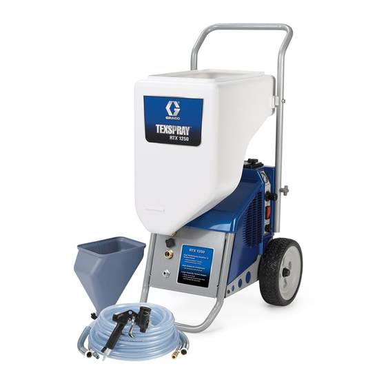
RTX 900 & RTX 1250
Models: 254974 and 254975
70 psi (0.49 MPa, 4.9 bar)
Maximum Fluid Working Pressure
Important Safety Instructions
Read all warnings and instructions in this manual.
Save these instructions.
Related Manuals
311777
311768
Graco Inc. P.O. Box 1441 Minneapolis, MN 55440-1441
Copyright 2006, Graco Inc. is registered to I.S. EN ISO 9001
For Water-Based Materials Only
Model 254975 Shown
US
C
Conforms to ANSI/UL
standard 1450
311772G
ti8867a
Advertisement
Table of Contents

Related Manuals for Graco RTX 900


Summary of Contents for Graco RTX 900
- Page 1 Repair Interior Texture Sprayers RTX 900 & RTX 1250 For Water-Based Materials Only Models: 254974 and 254975 70 psi (0.49 MPa, 4.9 bar) Maximum Fluid Working Pressure Important Safety Instructions Read all warnings and instructions in this manual. Save these instructions.
- Page 2 The following are general warnings related to the setup, use, grounding, maintenance and repair of this equipment. Additional, more specific warnings may be found throughout the body of this manual where applicable. Symbols appearing in the body of the manual refer to these general warnings. When these symbols appear through the manual, refer back to these pages for a description of the specific hazard.
- Page 3 Warnings Warnings Electric Shock Hazard To reduce the risk of electric shock: • Be sure sprayer is adequately grounded through electrical outlet, page 6. • Use only 3-wire, extension cords. • Make sure ground prongs are intact on sprayer and extension cords. •...
- Page 4 Warnings CAUTION Water or material remaining in unit when temperatures are below freezing can damage motor and/or delay pump startup. To insure water and material are completely drained out of unit: 1. Remove material line from sprayer. 2. Tip sprayer up as shown. ti9016a Before adding material or starting unit in cold weather, run warm water through pump.
-
Page 5: Component Identification
Pump Hose Outlet Air Hose Outlet Material Flow Gauge Material Flow Control ON/OFF Switch Selector Switch (Hopper Gun/Sprayer) Material Hopper - 10 gallon, RTX 900 Material Hopper - 12 gallon, RTX 1250 311772G Item Burp Guard Material/Air Hose Accessories Bag... -
Page 6: Pressure Relief Procedure
Pressure Relief Procedure To reduce risk of injury, follow this procedure whenever you see this symbol throughout this manual, Also, perform this procedure whenever you: • Stop spraying • Check or repair any part of this system • Install or clean spray nozzle 1. -
Page 7: Shroud Removal
Shroud Removal Disassembly 1. Relieve Pressure, page 6. 2. Unplug sprayer from outlet. ti2810b 3. Loosen bottom hopper fitting by hand and pull hopper up and off from handle. ti8871a 4. Loosen and remove 2 knobs (14) on sprayer handle (12). - Page 8 Reassembly 1. Angle left shroud half (5) into base and push down into place. Then replace right shroud half (7). ti9015a 2. Replace and tighten second screw (30). 3. Swing access door down (RTX 1250) and tighten knob (42). 4. Tighten screw (70) into lower right corner of side access plate.
- Page 9 RotoFlex™ II Pump (RTX 900) RotoFlex™ II Pump (RTX 900) Disassemble 1. Relieve Pressure, page 6. 2. Unplug sprayer from outlet. ti2810b 3. Remove Shroud, page 7. 4. Loosen and remove screw (28) on hose bracket. ti9009a 5. Remove hose bracket (25).
- Page 10 RotoFlex™ II Pump (RTX 1250) Disassemble 1. Relieve Pressure, page 6. 2. Unplug sprayer from outlet. ti2810b 3. Loosen knob (42) on side access panel. ti8870a 4. Remove screw (70) from side access panel. ti8874a 5. Pull access panel (13) out to release 3 fastening tabs and flip up to expose side access to pump.
- Page 11 RotoFlex™ II Pump (RTX 1250) Reassemble 1. Bend hose (16) so colored dots on hose fittings face each other. 2. Slide new pump hose (16) in from side access panel. Move pump rollers by hand until or flip power switch to rotate rollers until they are positioned cor- rectly with pump hose.
- Page 12 Use Compressor Repair Kit, 288612. Disassembly 1. Relieve Pressure, page 6. 2. Unplug sprayer from outlet. ti2810b 3. Remove Shroud, page 7. ™ 4. Remove RotoFlex II Pump hose; page 9 or 10. 5. Unscrew and remove grounding screw (49) from compressor.
- Page 13 Compressor Reassembly 1. Carefully position compressor back into sprayer body. Make sure piston head facing front of sprayer. ti8950a 2. Replace and tighten grounding screw (49). ti8941a 3. Reattach air lines to compressor. 4. Reattach 2 wires to compressor see Wiring Diagram, page 27.
- Page 14 Use Piston/Cylinder Repair Kit 288609. Disassembly 1. Relieve Pressure, page 6. 2. Unplug sprayer from outlet. ti2810b 3. Remove Shroud, page 7. ™ 4. Remove RotoFlex II Pump hose; page 9 or 10. 5. Remove Compressor, page 12. 6. Remove muffler (110) from head (74) by pulling straight out by hand.
- Page 15 Piston/Cylinder Reassembly CAUTION Piston and cylinder come packaged together. Do NOT let piston and cylinder come apart. If they do, make sure you drop the piston down through the top of the cylinder and tilt the piston as you pull it through the cylinder. Do NOT push the piston up from the bottom.
-
Page 16: Valve Plate
Use Valve Plate Repair Kit 288610. Disassembly 1. Relieve Pressure, page 6. 2. Unplug sprayer from outlet. ti2810b 3. Remove Shroud, page 7. ™ 4. Remove RotoFlex II Pump hose; page 9 or 10. 5. Remove Compressor, page 12. 6. Remove muffler (110) from head (74) by pulling straight out by hand. - Page 17 Motor Use Motor Repair Kit 288613. Disassembly 1. Relieve Pressure, page 6. 2. Unplug sprayer from outlet. ti2810b 3. Remove Shroud, page 7. ™ 4. Remove RotoFlex II Pump hose; page 9 or 10. 5. Remove Compressor, page 12. 6. Remove compressor from sprayer body and place it in a vice.
- Page 18 Reassembly 1. Angle motor pulley through compressor belt (84) and pull motor (71) into position. When replacing motor (71), make sure the square-shaped hole (SQ) is facing toward the out- side of the compressor. This hole will be used to torque the mounting bolts.
-
Page 19: Cooling Tube
Cooling Tube Use Cooler Repair Kit 288614. The cooling tube is extremely hot and can cause serious burns. Allow unit to completely cool before servicing the cooling tube. Disassembly 1. Relieve Pressure, page 6. 2. Unplug sprayer from outlet. ti2810b 3. - Page 20 Reassembly 1. Insert new cooling tube fitting and use 5/8 in. wrench to tighten. 2. Insert cooling tube (79) and push into new fitting (86). Make sure tube is fully seated. CAUTION When replacing cooling tube, make sure coil is facing up when you push the tubing into the fitting.
- Page 21 Idler Use Idler Repair Kit 288611. Disassembly 1. Relieve Pressure, page 6. 2. Unplug sprayer from outlet. ti2810b 3. Remove Shroud, page 7. ™ 4. Remove RotoFlex II Pump hose; page 9 or 10. 5. Remove Compressor, page 12. 6. Remove compressor belt, page 17. 7.
- Page 22 Use Roller Pulley Repair Kit 288616. Disassembly 1. Relieve Pressure, page 6. 2. Unplug sprayer from outlet. ti2810b 3. Remove Shroud, page 7. ™ 4. Remove RotoFlex II Pump hose; page 9 or 10. 5. Remove Compressor, page 12. 6. Use 7/32 in. allen wrench to loosen roller mounting bolt (87) and remove roller pulley (73).
- Page 23 Selector Switch Knob Use Knob Repair Kit 288756. Disassembly 1. Turn selector switch knob clockwise as far as it will 2. Use wrench to remove nut from knob. 3. Pull knob straight off from sprayer. Once knob has been removed, don’t move the exposed spline.
-
Page 24: Regulator Valve
Use Regulator Repair Kit 288757. Disassembly 1. Remove Knob, page 23. 2. Remove Shroud, page 7. 3. Use wrench to push against fitting (86) and carefully pull cooling tube (79) out. 4. Use phillips screwdriver to remove two screws. 5. Remove old regulator valve. Regulator Valve Assembly 1. -
Page 25: Troubleshooting
Troubleshooting Problem Sprayer won’t run Pump won’t pump material Material runs out of bottom of sprayer Pump hose worn out No air from compressor 311772G Troubleshooting Cause Power switch not on No power at wall outlet Wrong size generator Breaker tripped Air lock Selector switch in wrong position Mix too thick... - Page 26 Problem Speed of application slow or slower Intermittent flow/sputtering Quick disconnect does not stay con- nected. Gun will not shut off Fluid leaking at Flow Adjustment Nut Damaged seal. Fluid leaking out of either plug Needle adjustment won’t adjust Cause Material too thick Nozzle too small Too much air being used.
-
Page 27: Wiring Diagram
Wiring Diagram Green Wire (GND) Power Cord Black Wire RTX 900 Air Valve Cylinder Relief Valve Manifold on Compressor Air Outlet 311772G Wiring Diagram White Wire Motor Switch Air Diagram Cylinder ti9232a Compressor ti8937a RTX 1250 Gauge Air Valve Regulator... - Page 28 Parts Parts Models 254974 and 254975 (RTX 900) (RTX 1250) (RTX 900) ti8901c (RTX 900) (RTX 900) 311772G...
- Page 29 Parts • RTX 1250 Only 311772G Parts Models 254974 and 254975 RTX 1250 Only • • • ti8902b...
- Page 30 ™ 288757 120744 120637 15C753 SCREW, machine, hex 111831 15H912 GUARD, burp 15K323 LABEL, hopper, RTX 900 15K329 LABEL, control, RTX 900 15K335 LABEL, front, RTX 900 15K338 LABEL, shroud, RTX 900 120215 120567 115099 ▲ Additional warning labels are available at no cost.
- Page 31 Parts Ref Part Description 288386 PLATE, front, RTX 15J600 TOOLBOX 15H069 SUPPORT, hopper, RTX 288384 FRAME, back, RTX (painted) 288650 COVER, shroud 277319 SHIELD, bottom 288382 COVER, shroud (painted) 15J671 AXLE, RTX 1250 115094 WHEEL, 10 112612 CAP, hub 288314 HANDLE, RTX (painted) 15H641 KNOB 288336 FITTING, bulkhead, assembly 288623 HOSE, coupled...
- Page 32 Ref. Part Description 288856 KIT, repair, compressor, complete (includes all items) RTX 900 288651 KIT, repair, compressor, complete (includes all items) RTX 1250 288612 KIT, repair, compressor, rebuild (includes 100, 74, 86, 75, 76, 77, 87) 288613 KIT, repair, motor, universal, 120v...
-
Page 33: Technical Data
16 AWG, 3-wire, 25 ft Model 254974: 8 gallons Model 254975: 10 gallons Gun material hopper: 3/4 gallon RTX 900 - 0.9 gpm (3.4 lpm) RTX 1250 - 1.25 gpm (4.7 lpm) 23 in. (584 mm) with handle 18 in. (456 mm) 40 in. -
Page 34: Graco Standard Warranty
Graco Standard Warranty Graco Standard Warranty Graco warrants all equipment referenced in this document which is manufactured by Graco and bearing its name to be free from defects in material and workmanship on the date of sale the original purchaser for use. With the exception of any special, extended, or limited warranty published by Graco, Graco will, for a period of twelve months from the date of sale, repair or replace any part of the equipment determined by Graco to be defective.
Need help?
Do you have a question about the RTX 900 and is the answer not in the manual?
Questions and answers