Advertisement
Quick Links
*18762*
18762
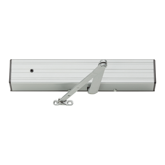
Door closer with electronic release & Multi-point hold open
1
Closer Installation
1a
Closer Information
Closer is handed at the factory. The hand of the closer must match
the hand of the door (see the door handing diagram below).
1b
Voltage
Voltage supplied to the door frame MUST match voltage of the
solenoid.
1c
Before beginning this step, determine which type of
wiring option will be used, and follow the
corresponding instructions:
Concealed Wiring: see Figure 3 on page 3.
a. Prepare the frame per the
proper template on page
4. Be sure all the holes are
dimensioned correctly before
drilling and tapping.
b. Assemble the conduit
connector provided to the
flexible conduit, then attach to
the hole in the mounting plate.
c. Secure the mounting plate
to the frame with the screws
provided.
Surface Wiring: see Figure 4 on
page 3.
L NOTE: Remove the knockout in the top of the cover.
a. Prepare the frame per the proper template on page 4. Be sure
all the holes are dimensioned correctly before drilling and
tapping.
b. Secure the mounting plate to the frame with the screws
provided.
c. Attach the surface run Z\x" EMT conduit to the hole in the
bracket on the mounting plate. Be sure the conduit is securely
attached to the bracket.
Customer Service
1-877-671-7011
www.allegion.com/us
4310ME Series
!
WaRNiNg
!
HaZaRDOUS VOLTagE
CaN SHOCK aND CaUSE
SEVERE iNJURY
Disconnect power before
making any electrical
connections or performing
maintenance.
HOW TO TELL HAND OF DOOR:
LEFT
HAND
DOOR
1d
Wiring Connections
Make the wiring connections at this time. Connect the two black
wires to the input voltage (polarity is not important). The green wire
MUST be connected to an earth ground (see Figures 3 & 4 on page
3).
1e
Spacer/Arm
Place the spacer on the closer shaft, slide the arm onto the closer
shaft, and secure it with the arm shaft screw (see Figure 1 on page
3).
1f
Track Roller
Insert the track roller into the track, and end caps into both ends of
the track. Place track plugs in the track where needed. Using the
fasteners provided, mount the track on the door per the template on
page 4.
!
1g
Set Screw
Loosen the set screw in the end of the arm, open the door
approximately 30˚, pull the arm over the top of the door and
connect to the track roller. Tighten the set screw firmly.
1h
Electric Checkout
Regulate the closer and perform an electrical checkout, as
instructed on page 2, before installing the closer cover.
1i
Disengage the Swing Free Arm
To disengage the swing-free action of the arm, insert the locking
screw (stored in the tube portion of the arm) into the shaft end of
the arm, and tighten securely.
RIGHT
HAND
DOOR
Installation Instructions
33 ft-lbs
=
45 N-m
58 N
MAXIMUM OPENING FORCE
© Allegion 2014
Printed in U.S.A.
18762 Rev. 01/14-m
Advertisement

Related Manuals for LCN 4310ME Series


Summary of Contents for LCN 4310ME Series
- Page 1 *18762* 4310ME Series 18762 Door closer with electronic release & Multi-point hold open Installation Instructions Wiring Connections Closer Installation Make the wiring connections at this time. Connect the two black Closer Information wires to the input voltage (polarity is not important). The green wire MUST be connected to an earth ground (see Figures 3 &...
- Page 2 Improper installation or regulation may result in personal counterclockwise injury or property damage. Follow all instructions carefully. to decrease For questions, call LCN at the holding force 877-671-7011 Electrical Checkout after completion of installation & wiring, and with the unit...
- Page 3 Figure 1 Mounting Bracket For Surface Run Conduit Cover Hole For Concealed Conduit Connection Spring Power Adjustment Track Roller Cover Screws Spacer Assy. Shaft Locking Screw Track Screw Plug Figure 2 Backcheck Main Speed Latch Speed Turns Latch Max. Main Speed Speed Backcheck...
- Page 5 Release Date White Paper D. myers m. Sasso 043228 01-01-14 Notes Title 1. printed two sides 4310mE Series Instruction Sheet 2. printed black Creation Date Number Revision 3. tolerance ± .13 05-10-10 4. printed in country may vary 18762 5. drawings not to scale...
Need help?
Do you have a question about the 4310ME Series and is the answer not in the manual?
Questions and answers