Table of Contents
Advertisement
Quick Links
Advertisement
Table of Contents

Subscribe to Our Youtube Channel
Related Manuals for ICOP Technology PPC-150P-D2N4N-GE


Summary of Contents for ICOP Technology PPC-150P-D2N4N-GE
- Page 1 User’s Manual PPC-150P DMP Vortex86 DX2 / DX3 Processor Compact Panel PC with 15” PCAP Touchscreen PPC-150P-D2 Series with DX2 processor PPC-150P-D3 Series with DX3 processor (Revision 1.0A) PPC-150P User’s Manual IUMPPC150P-01 Ver.1.0A Aug, 2018...
- Page 2 REVISION DATE VERSION DESCRIPTION 2018/8/31 Version 1.0A New Release PPC-150P User’s Manual IUMPPC150P-01 Ver.1.0A Aug, 2018...
- Page 3 No part of this manual may be reproduced, copied, translated or transmitted, in whole or in part, in any form or by any means without the prior written permission of the ICOP Technology Inc. Copyright 2018 ICOP Technology Inc. Manual # IUMPPC150P-01 Ver.1.0A Aug, 2018 TRADEMARKS ACKNOWLEDGMENT Vortex86DX2...
- Page 4 SAFETY INFORMATION Read these Safety instructions carefully. Please carry the unit with both hands, handle carefully. Make sure the voltage of the power source is correct before connecting the equipment to the power outlet. Do not expose your Panel PC to rain or moisture in order to prevent shock and fire hazard.
-
Page 5: Table Of Contents
Content Content ........................... iv Ch. 1 General Information ....................1 1.1 Product Description ....................2 1.2 Product Specifications .................... 3 1.3 Inspection standard for TFT-LCD Panel ..............5 1.4 Product Dimensions ....................8 1.5 Panel Mounting Instruction ................... 10 1.6 Ordering Information ..................... 12 Ch. -
Page 6: Ch. 1 General Information
General Information 1.1 Product Description 1.2 Product Specifications 1.3 Inspection standard for TFT-LCD Panel 1.4 Product Dimensions 1.5 Mounting Instruction 1.6 Ordering Information PPC-150P User’s Manual IUMPPC150P-01 Ver.1.0A Aug, 2018... -
Page 7: Product Description
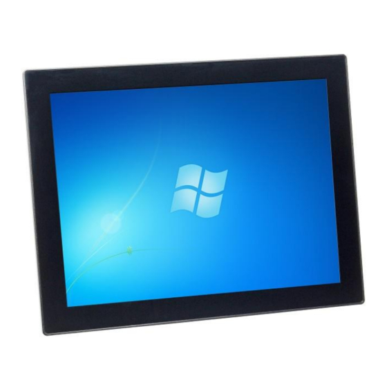
1.1 Product Description ICOP Technology Inc. is proudly going to release a brand new Panel PC, which offers fanless design, low power consumption, and IP65 front panel. The PPC-150P is powered by DMP’s latest Vortex86DX2 and DX3 SoCs, the 3... -
Page 8: Product Specifications
1.2 Product Specifications CPU BOARD SPECIFICATIONS DM&P Vortex86DX2- 933MHz / DX3-1GHz DX2: L1:16KB I-Cache, 16KB D-Cache L2: 256KB Cache Cache DX3: L1:32KB I-Cache, 32KB D-Cache L2: 512KB Cache BIOS AMI BIOS Memory 512MB / 1GB / 2GB DDR2(DDR3) onboard Software Programmable from Watchdog Timer 30.5u to 512 seconds x 2 sets Integrated 10/100M Ethernet X1... - Page 9 0~+50°C (+32~+122°F) / Operating Temperature -20~+60°C (-4~+140°F; DX2 with 800MHz) Storage Temperature -30~+70°C (-22~ +158°F) Operating Humidity 0% ~ 90% Relative Humidity, Non-Condensing Dimensions 354.85x280.85x54.9mm (13.97"x11.06"x2.16") Weight 4.00 Kg Protection IP65 Front Panel Certification CE / FCC / VCCI / Vibration/ Shock LCD SPECIFICATIONS Display Type 15”...
-
Page 10: Inspection Standard For Tft-Lcd Panel
1.3 Inspection standard for TFT-LCD Panel DEFECT TYPE LIMIT Note φ<0.15mm Ignore 0.15mm≦φ≦0.5mm N≦4 SPOT Note1 0.5mm<φ 0.03mm<W≦0.1mm, L≦5mm N≦3 FIBER Note1 VISUAL 1.0mm<W, 1.5mm<L INTERNAL DEFECT φ<0.15mm Ignore POLARIZER 0.15mm≦φ≦0.5mm N≦2 Note1 BUBBLE 0.5mm<φ It’ OK if mura is slight visible through 6%ND filter Mura A Grade B Grade... - Page 11 (a) White / Black Spot (b) Polarizer Bubble [ Note 2 ] Bright dot is defined through 6% transmission ND Filter as following. [ Note 3 ] Display area C Area: Center of display area O Area: Outer of display area [ Note 4 ] Judge the defect dot and the adjacent dot as following.
- Page 12 R Defect Dot Adjacent Dot The defects that are not defined above and considered to be problem shall be reviewed and discussed by both parties. Defects on the Black Matrix, out of Display area, are not considered as a defect or counted. PPC-150P User’s Manual IUMPPC150P-01 Ver.1.0A Aug, 2018...
-
Page 13: Product Dimensions
1.4 Product Dimensions PPC-150P User’s Manual IUMPPC150P-01 Ver.1.0A Aug, 2018... - Page 14 PPC-150P User’s Manual IUMPPC150P-01 Ver.1.0A Aug, 2018...
-
Page 15: Panel Mounting Instruction
1.5 Panel Mounting Instruction Cut a mounting hole in the panel. (Refer to PPC‐150P Dimensions on page 11~12.) (Note 1) Check and remove the twelve M3 screws in a diagonal pattern as image below if necessary. Place PPC‐090T face‐down on a clean, flat surface. Slide the panel cutout around the back of PPC‐150P, until the panel rests directly on the gasket. - Page 16 Note 1: It is strongly recommended that a professional machine shop cut the mounting hole in the panel. Note 2: The length for all twelve M3 screws will be according to the thickness of mounting panel. For example: The length of standard M3 screws for PPC-150P is 6mm. If the thickness of your mounting panel is 3mm and washer thickness is 1mm, you have to use 10mm M3 screw.
-
Page 17: Ordering Information
1.6 Ordering Information Product CPU Type CPU Clock Flash onboard Code Size 090T D2 (DX2) W(800MH) 3(512B) N (No Flash) GE (GigaLAN) 104T D3 (DX3) N(933MHz) 4 (1GB) A (256MB) G7C (GigaLAN + 7 COMs) 150T G (1GHz) 5 (2GB) B (512MB) G7CP (GigaLAN + 7 COMs + PoE) 150P... - Page 18 PART NUMBER DESCRIPTION 15” Panel PC w/DX2/1GB Memory/PCAP Touch/ PPC-150P-D2N4N 3USB/AUDIO/LAN/2COM/DC12~24V 15” Panel PC w/DX2/1GB Memory/PCAP Touch/ PPC-150P-D2N4N-GE 3USB/AUDIO/LAN/GIGA LAN/2COM/ DC12~24V 15" Panel PC w/DX2/1GB Memory/PCAP Touch/ PPC-150P-D2N4N-G7CP 3USB/AUDIO/LAN/GIGA LAN/7COM/PoE 15" Panel PC w/DX2-800MHz/1GB Memory/ PCAP PPC-150P-D2W4N-GE Touch/3USB/AUDIO/LAN/GIGA/LAN/2COM/ DC12~24V/Wide Temp 15”...
-
Page 19: Ch. 2 System Installation
System Installation 2.1 CPU Board Outline 2.2 Connector Summary 2.3 Connector Pin Assignments 2.4 External I/O Overview 2.5 External I/O Pin Assignment 2.6 Watchdog Timer PPC-150P User’s Manual IUMPPC150P-01 Ver.1.0A Aug, 2018... -
Page 20: Cpu Board Outline
2.1 CPU Board Outline PPC CPU Board PPC-150P User’s Manual IUMPPC150P-01 Ver.1.0A Aug, 2018... -
Page 21: Connector Summary
2.2 Connector Summary Description Type of Connections Pin # Power Terminal Connector External Power Plug 3-pin COM1 (RS232/422/485) External D-Sub Male Connector 9-pin External USB Connector 6-pin External USB Connector 6-pin PS/2Keyboard External Mini DIN Socket 6-pin External USB Connector 6-pin (WLAN Optional) Internal USB Connector... -
Page 22: Connector Pin Assignments
2.3 Connector Pin J7: USB Assignments Pin # Signal Name Pin # Signal Name USBD4- J1: Power Terminal Connector USBD4+ Pin # Signal Name +12~24V J8: USB (WLAN Optional) Pin # Signal Name Pin # Signal Name USBD1- J3 & J14: COM1 & 2 (RS232/422/485) USBD1+ Pin # Signal Name... - Page 23 J33/J34/J35/J36: GPIO 180-pin (Optional for I/O extension board on Ch.5) Signal Signal Signal Signal Signal Signal Signal Signal Pin# Pin# Pin# Pin# Pin# Pin# Pin# Pin# Name Name Name Name Name Name Name Name SBHE GP34 GP35 RSTDRV IRQ3 GP36 GP37 GP90 GP91...
-
Page 24: External I/O Overview
2.4 External I/O Overview GIGA Ethernet (Optional) PS/2 KB USB 2.0 PORT Audio-Out Power Switch 10/100Mbps RS-232/422/485 Ethernet +12 ~ 24VDC NOTE GIGA LAN, Wireless are optional RS232/422/485 is selected by BIOS setting PPC-150P User’s Manual IUMPPC150P-01 Ver.1.0A Aug, 2018... -
Page 25: External I/O Pin Assignment
J4/J5/J7: USB External Pin # Signal Name Assignment USB0- USB0+ Power Switch Pin # Status GGND GGND RJ45 Signal Signal Power Connector DC-IN +12~24V Pin # Pin # Name Name Pin # Signal Name FTXD+ FTXD- +12~24V FRXIN+ FRXIN- PS/2 Keyboard Pin # Signal Name KBCLK... -
Page 26: Watchdog Timer
2.6 Watchdog Timer There are two watchdog timers in PPC-150P, we also provide DOS, Linux and WinCE example for your reference. For more technical support, please visit: http://tech.icop.com.tw or download the PDF file: dmp.com.tw/tech PPC-150P User’s Manual IUMPPC150P-01 Ver.1.0A Aug, 2018... -
Page 27: Ch. 3 Hardware Installation
Hardware Installation PPC-150P supports various kinds of storages for industrial application, divided into SATA Slim, CompactFlash or SD card (optional). 3.1 Installing the SATA Slim 3.2 Installing the Compact Flash PPC-150P User’s Manual IUMPPC150P-01 Ver.1.0A Aug, 2018... -
Page 28: Installing The Sata Slim
3.1 Installing the SATA Slim [SPEC] JEDEC SFF-8156 standard form factor 53 x 32 x 4.0 mm [SATA SLIM MLC LIST] Operating Temperature 0℃ ~ +70℃ SDM-SST-SLIM(M)-4G 0℃ ~ +70℃ SDM-SST-SLIM(M)-8G 0℃ ~ +70℃ SDM-SST-SLIM(M)-16G 0℃ ~ +70℃ SDM-SST-SLIM(M)-32G 0℃ ~ +70℃ ISATA-SLIM(M)-8G 0℃... - Page 29 Place the SATA slim horizontally aligned and gently put into the socket until you feel a click. Insert all eight screws into the screw holes. PPC-150P User’s Manual IUMPPC150P-01 Ver.1.0A Aug, 2018...
-
Page 30: Installing The Compact Flash
3.2 Installing the Compact Flash [STEP] Remove the nine screws in a diagonal pattern as the image below. ○ ○ ○ ○ ○ ○ ○ ○ Gently insert the CF card along the track. Caution: Please watch out for the direction which the CF card has to be face up. -
Page 31: Ch. 4 Driver Installation
Driver Installation 4.1 PPC-150P Development Note 4.2 BIOS Default Setting 4.3 Serial Ports Setting (RS232/RS422/RS485) PPC-150P User’s Manual IUMPPC150P-01 Ver.1.0A Aug, 2018... - Page 32 The Vortex86DX2 / DX3 processor is integrated RDC Display chip which is an ultra-low powered graphics chipset with total power consumption at around 1-1.5 W. The Vortex86DX2 / DX3 processor is integrated 10/100Mbps Ethernet controller that supports both 10/100BASE-T and allows direct connection to your 10/100Mbps Ethernet based Local Area Network for full interaction with local servers, wide area networks such as the Internet.
-
Page 33: Ppc-150P Development Note
4.1 PPC-150P Development Note < WINDOWS DEVELOPMENT GUIDE > Windows Embedded CE 6.0 BSP, Windows Embedded Compact 7 BSP, and Windows Embedded Standard 2009 trial image with development notes, please visit technical website to get more information at http://tech.icop.com.tw/. < LINUX INSTALLATION NOTE> Please visit Linux... -
Page 34: Bios Default Setting
4.2 BIOS Default Setting If the system cannot be booted after BIOS changes are made, Please follow below procedures in order to restore the CMOS as default setting. Press < End > Key, when the power on Press < Del > to enter the AMI BIOS setup Press <... -
Page 35: Serial Ports Setting (Rs232/422/485)
4.3 Serial Ports Setting (RS232/422/485) For DX2 processor: Please press <Del> to get into the BIOS settings after booting the machine, and follow the steps below: [Step 1] Use the arrow key to select the category “Chipset” on the top of the menu, then select SouthBridge Configuration in the sub menu and press <Enter>... - Page 36 [Step 2] Use the arrow key to select “TXDEN Serial Port Type Configuration” and press <ENTER> [Step 3] Choose the port you would like to change. For example, choose TXDEN1 for COM1 and press <Enter>. You will then see three options; select the desired type and press <Enter>...
- Page 37 The Serial Ports setting is finished [Step 4] Press <Esc> twice to get back to the T op Menu. Use the arrow key to the category “Exit”, and select the option “Save Changes and Exit”. PPC-150P User’s Manual IUMPPC150P-01 Ver.1.0A Aug, 2018...
- Page 38 Press <Enter> and choose [OK] to keep your changes, then the device will reboot automatically. PPC-150P User’s Manual IUMPPC150P-01 Ver.1.0A Aug, 2018...
- Page 39 For DX3 processor: Please press <Del> to get into the BIOS settings after booting the machine, and follow the steps below: [Step 1] Use the arrow key to select the category “Advanced” on the top of the menu, then select "Serial/Parallel Port Configuration" in the sub menu and press <Enter> [Step 2] Choose the port you would like to change.
- Page 40 The Serial Ports setting is finished [Step 3] Press <Esc> twice to get back to the T op Menu. Use the arrow key to the category “Exit”, and select the option “Save Changes and Exit”. PPC-150P User’s Manual IUMPPC150P-01 Ver.1.0A Aug, 2018...
- Page 41 Press <Enter> and choose [OK] to keep your changes, then the device will reboot automatically. PPC-150P User’s Manual IUMPPC150P-01 Ver.1.0A Aug, 2018...
-
Page 42: Ch. 5 Extension I/O (Optional)
Extension I/O (Optional) 5.1 Extension I/O Overview 5.2 External I/O Pin Assignment PPC-150P User’s Manual IUMPPC150P-01 Ver.1.0A Aug, 2018... -
Page 43: Extension I/O Overview (Optional)
5.1 Extension I/O Overview (Optional) NOTE: Those COM ports are only for RS232 signals. DSub-25pin only can be set to be either one of COM5 & COM6 16-bit GPIO by hardware settings, and user can't change hardware setting there. Thus, please contact your region sales person to order correct part number in advance. -
Page 44: Extension I/O Pin Assignment (Optional)
5.2 Extension I/O Pin Assignment (Optional) COM3, 4 and 9 (RS232) (Change setting by BIOS) Pin # Signal Name Pin # Signal Name DCD1 RXD1 TXD1 DTR1 DSR1 RTS1 CTS1 COM5 & 6 (RS232) / 16-bit GPIO Pin # Signal Name Pin # Signal Name VCC (+5V_Output) -
Page 45: Warranty
Merchandise Authorization (RMA) number. Returned goods should always be accompanied by a clear problem description. All Trademarks appearing in this manuscript are registered trademark of their respective owners. All Specifications are subject to change without notice. © ICOP Technology Inc. 2018 PPC-150P User’s Manual IUMPPC150P-01 Ver.1.0A Aug, 2018...
Need help?
Do you have a question about the PPC-150P-D2N4N-GE and is the answer not in the manual?
Questions and answers