Table of Contents
Advertisement
Quick Links
421AA1898
SPECIFICATIONS
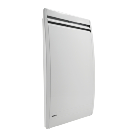
One design, two comfort solutions. The Allegro is a natural
convection unit with a unique design and all the CONVECTAIR
advantages. Use it with the optional CONVECTAIR Programmer
module (pilot wire) allowing scheduled temperature set-backs in
periods of prolonged absence. Same comfort, more savings.
PLANNING THE INSTALLATION
CONVECTAIR recommends that the Allegro be installed by
a qualified electrician, in accordance with national codes,
local authority having jurisdiction.
If you plan to control the Allegro with CONVECTAIR's
Programmer module, the installation must be done using
three-conductor wiring (3/12). You may also use regular
two-conductor wire combined with a FAS 105 2/18 using only
one of the two wires (please refer to the installation guide of
the Programmer 7392 or contact CONVECTAIR for more
information).
1. Choose the location where the Allegro will be installed
(Fig. 2). It must be installed 4 in (10 cm) from the floor.
2. Ensure that there are no restrictions to the minimum
clearances permitted which are: 20 in (52 cm) in front,
6 in (15 cm) on each side and 4 in (10 cm) on top
of the Allegro.
USE MOUNTING BRACKET
AS A TEMPLATE
FOR MARKING
WALL
FLOOR
ALLEGRO
INSTALLATION NOTICE
READ BEFORE OPERATING / INSTALLING DO NOT DISCARD
LOCKING
BRACKET
B MARK
8 1
1
2 /
i n
7 4
m c
7 1/8 in
18 cm
Fig. 1
7300 BB or BM
INSTALLATION
To avoid unnecessary length of cable behind the unit, be sure
that the supply cable comes out from the wall at the correct height
(Fig. 4). Should the unit be installed on an outside wall, it is
suggested to take out the supply wire behind the middle of the
unit since it is hard to reinsert excess wiring in an outside wall.
1. Free the mounting bracket by pressing and pulling both
locking brackets (Fig. 2).
2. Use the mounting bracket as a template by holding against
the wall flush to the floor. Use the B mark to locate the
bottom fasteners (Fig. 1).
3. Relocate the mounting bracket to match the marks with the
holes for the bottom fasteners.
4. Make sure that the mounting bracket is level then mark
the 3 or 4 holes for fastening.
5. Place the mounting bracket and fasten it with screws.
Catalog
Wattage
number
240V
7300-C07
750W
7300-C10
1000W
7300-C12
1250W
7300-C15
1500W
7300-C17
1750W
7300-C20
2000W
7
0 5
W
W i d t h
A
0 1
i n
2
5 , 5
m c
C a b l e
e n t r y
5
2 / 1
i n
4 1
m c
2 1
i n
0 3
m c
Height
Width
208V
cm in
cm
563W
47 18 1/2
48,9
750W
47 18 1/2
56,9
938W
47 18 1/2
64,9
1125W
47 18 1/2
76,9
1313W
47 18 1/2
84,9
1500W
47 18 1/2
84,9
O t h e r w a t
3
3
8 /
i n
A
7 , 8
m c
8 1
1
2 /
i n
7 4
m c
W i d t h
A
in
cm
in
19 1/4
17,8
7
22 1/2
24,8
9 3/4
25 1/2
32
12 1/2
30 1/4
40,5
16
33 3/8
40,5
16
33 3/8
40,5
16
t a g e s
0 1
i n
2
5 , 5
m c
C a b l e
e n t r y
5
2 / 1
i n
4 1
m c
2 1
i n
0 3
m c
Fig. 2
Advertisement
Table of Contents

Subscribe to Our Youtube Channel
Related Manuals for CONVECTAIR Allegro 7300-C07


Summary of Contents for CONVECTAIR Allegro 7300-C07
- Page 1 One design, two comfort solutions. The Allegro is a natural To avoid unnecessary length of cable behind the unit, be sure convection unit with a unique design and all the CONVECTAIR that the supply cable comes out from the wall at the correct height advantages.
- Page 2 This wire will be used only if the Allegro is First, detach the unit from the wall bracket. Behind the setting dial, connected to CONVECTAIR’s Programmer module. two pins are provided. Remove the pins with pliers by rotating 6. Carefully put back all wires inside the junction box, gently.
- Page 3 5 years on heating elements. out through the louvres. This coloration can be reduced by cleaning the louvres on a weekly basis. All CONVECTAIR units are subject to a double warranty: 2 years on all parts and manufacturing defects and 5 years MAINTENANCE on the heating elements themselves.
Need help?
Do you have a question about the Allegro 7300-C07 and is the answer not in the manual?
Questions and answers