Table of Contents
Advertisement
Quick Links
Advertisement
Table of Contents

Related Manuals for Sanwa SP21


Summary of Contents for Sanwa SP21
- Page 1 SP21 マルチテスタ MULTITESTER 取扱説明書 INSTRUCTION MANUAL...
-
Page 2: Table Of Contents
目 次 【1】安全に関する項目〜ご使用前に必ずお読みください〜… …………1 1-1 警告マークなどの記号説明… ………………………………………1 1-2 安全使用のための警告文… …………………………………………1 1-3 最大過負荷保護入力値… ……………………………………………3 【2】用途と特長… ……………………………………………………………5 2−1 用 途… … ……………………………………………………………5 2−2 特 長… … ……………………………………………………………5 【3】各部の名称… ……………………………………………………………6 【4】指示の読み取り方… ……………………………………………………7 【5】機能説明… ………………………………………………………………9 5−1 つまみ・調整器… … …………………………………………………9 5−2 スタンドの使い方… … ………………………………………………9 【6】測定方法… …………………………………………………………11 6−1 始業点検… … ……………………………………………………11 6−2 レンジの設定方法 (最適レンジの設定) … … …………………13 6−3 測定前の準備… … ………………………………………………13 6−4 電圧... - Page 3 7-3 How to Replace Battery and Fuse ………………………… 35 7-4 Storage ………………………………………………………… 38 【8】AFTER-SALE SERVICE ………………………………………… 38 8-1 Repair ………………………………………………………… 38 8-2 For Information or Enquiries ………………………………… 40 8-3 Sanwa Web Site ……………………………………………… 40 ……………………………………………… 42 【9】SPECIFICATIONS 9-1 General Specification ………………………………………… 42 9-2 Optional Accessories ………………………………………… 42...
-
Page 4: 1】安全に関する項目〜ご使用前に必ずお読みください
【1】安全に関する項目〜ご使用の前に必ずお読みください〜 このたびはアナログマルチメータ SP21 型をお買い上げいただき、 誠にありがとうございます。 ご使用前にはこの取扱説明書をよくお読みいただき、正しく安全 にご使用ください。そして常にご覧いただけるように製品と一緒に して大切に保管してください。 ・・・ ・ 本文中の“ 警告”および“ 注意”の記載事項は、や けどや感 ・ 電 などの事故防止のため、必ずお守りください。 1-1 警告マークなどの記号説明 本器および 『取扱説明書』 に使用されている記号と意味について :安全に使用するための特に重要な事項を示します。 ・警告文はやけどや感電などの人身事故を防止するためのものです。 ・注意文は本器を壊すおそれのあるお取り扱いについての注意 文です。 :直流電圧 (DCV) … :グランド 〜:交流電圧 (ACV) … +:プラス Ω:抵抗… −:マイナス :ブザー… :ヒューズ :ヒューズとダイオードによる回路保護… :二重絶縁または強化絶縁 :耐落下 1-2 安全使用のための警告文 警 告... -
Page 5: Explanation Of Warning Symbols
【1】 …………SAFETY PRECAUTIONS:Before use,read the following safety precautions This instruction manual explains how to use your multimeter SP21 safely. Before use,please read this manual thoroughly. After reading it,keep it together with the product for reference to it when necessary. The instruction given under the heading “ …WARNING” “ CAUTION”... -
Page 6: 最大過負荷保護入力値
……7.…ヒューズは必ず指定定格および仕様のものを使用すること 。 ヒューズの代用品を用いたり短絡することは絶対にしない こと。 ……8.…測定中はテストリードのつばよりテストピン側を持たないこと。 ……9.…測定中は他のファンクションまたは他のレンジに切り換え たりしないこと。 10.…測定ごとのレンジおよびファンクション確認を確実に行うこと。 11.…本器または手が水などでぬれた状態での使用はしないこと。 12.…強力な電磁波を発生するもの、帯電しているものの近くで は使用しないこと。 13.…内蔵電池および内蔵ヒューズ交換を除く修理・改造は行わ ないこと。 14.…年1回以上の点検は必ず行うこと。 15.…屋内使用。 1-3 最大過負荷保護入力値 … ファンクション(レンジ) … 入力端子… 最大定格入力値… 最大過負荷保護入力値 DCV…30〜600 DC…1000…V,AC…750…V または…PEAK…MAX…1100…V ACV…30〜600 DCV…0.3〜12 各レンジ *DC,AC…200…V 最大目盛値 または…PEAK…MAX…250…V ACV…12 DCA…30…m/0.3 +,− *DC,AC…0.5…A DCA…60μ *DC,AC…1…mA Ω… 電流・電圧 *DC,AC…200…V 入力禁止... -
Page 7: Maximum Overload Protection Input
5.…Never use meter if the meter or test leads are damaged or broken. 6.…Never use uncased meter. 7.…Be sure to use a fuse of the spesified rating or type. Never use a substitute of the fuse or never make a short circuit of the fuse. -
Page 8: 2】用途と特長
【2】用途と特長 2-1 用 途 本器は小容量電路の測定用に設計された、携帯用アナログマルチ メータです。小型通信機器や家電製品、電灯線電圧や各種電池の測 定などはもちろん、NULLメータやブザー機能で回路分析などにも 威力を発揮します。 2-2 特 長 ・耐ショック・トートバンドメータ搭載 ・スタンド機能付き ・ゼロセンター (NULL) メータにて±DCVの測定が可能 ・導通チェックブザー付き ・本体ケースおよび回路基板には難燃材を使用 ・回路保護はヒューズとダイオードによる二重保護 【2】APPLICATION AND FEATURES 2-1 Application This instrument is port able multimeter designated for measuremaent of week current circuit. 2-2 Features ・Band meter of drop shock type with high sensitivity has been employed. -
Page 9: 3】各部の名称
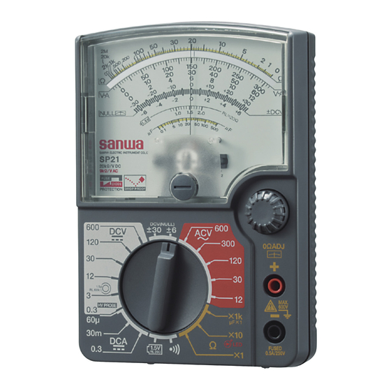
【3】各部の名称 NAME OF COMPONENT UNITS 目盛板 メータカバー Scale Meter cover 指針 パネル Pointer Panel 0…Ω・ メータ0位置調整器 調整つまみ Zero position adjuster 0 Ω・ adjuster knob +入力端子 +input terminal レンジ切り換えつまみ Range selector knob −入力端子 ・着脱式テストピンキャップ装着時 :CAT.III 600 V −input terminal ・着脱式テストピンキャップ未装着時:CAT.II 1000 V ・ When the removable test pin covers are mounted : CAT.III 600 V ・... -
Page 10: 4】指示の読み取り方
【4】指示の読み取り方 SCALE READING... - Page 11 使用レンジ 読み取り倍率 使用レンジ 読み取り倍率 Range Multiplier Range Multiplier Ω ×1 k × 1 k ( 1000) × 10 DCV 120 Ω×10 ×10 ×1 ① DCV 12 ④ Ω×1 ×1 ×10 ACV 120 ×0.1 ×1 DCV 30 ACV 12 DCV 3 ×0.01 ±DCV 30 ×1...
-
Page 12: 5】機能説明
【5】機能説明 DESCRIPUTION OF FUNCTIONS 5-1 つまみ・調整器 ○レンジ切り換えつまみ このつまみを回すと 、レンジおよびファンクションが切り換わります。 ○メータ0位調整器 この調整器つまみを回し、メータ指針を 0 位 置 (目盛板左端) に合 わせます。 ○0 Ω・ ……調整つまみ 抵抗や±DCV測定のとき使用します。 … ・ テストピンをショートし、Ωの時は目盛板の右端 (Ω目盛の0位 置) にこのつまみを回し指針を合わせます。 ±DCVの時は自動的に指針が振れますので目盛板の中央 (± DCV目盛の0位置) にこのつまみを回し指針を合わせます。 5-2 スタンドの使い方 リヤケース側にあるスタンドを図のようにして立ててご使用くだ さい。 5-1 Knob and Adjuster ○Range selector knob Turn this switch to turn on select the function and ranges. ○Zero position adjuster This adjuter knob is turn and meter pointer is adjusted to 0 point (scale left edge). - Page 13 ●スタンドの使い方 How to use the stand...
-
Page 14: 6】測定方法
【6】測定方法 6-1 始業点検 警 告 1.…本体およびテストリードが傷んでいたり、壊れている場合は 使用しないこと。 2.…テストリードが切れたりしていないことを確認すること。 【6】MEASUREMENT PROCEDURE 6-1 Start-up Inspection WARNING 1.…Never use meter if the meter or test leads are damaged or broken. 2.…Make sure that the test leads are not cut or otherwise damaged. - Page 15 スタート START 壊れている 本体および Damaged テストリードの外観が 壊れていませんか? Main unit and test leads damaged ? そのま ま使用 せず、修… 壊れていない 理を依頼してください。 No damaged Stop using it and have it repaired. テストリードおよび ヒューズの断線確認 Check continuity of test leads and fuse. 振れない 指針が大きく右 ①レンジ切り換えつまみを へ振れますか?...
-
Page 16: 6−2 レンジの設定方法 (最適レンジの設定
6-2 レンジの設定方法 (最適レンジの設定) ①電圧 (V) 、電流 (A) 測定時の最適なレンジ 6…Vを測定する場合は 12…V レンジ、15…Vの場合は 30…Vレンジと いうように、測定する値よりも大きく、かつ近いレンジを選び ます。 測定値の見当がつかない場合は最大レンジで測定してみます。 ②抵抗 (Ω) 測定時の最適なレンジ なるべく中央寄りの指示をするレンジを選びます。 例えば1…kΩの測定では×1…kではなく、×10を選びます。 6-3 測定前の準備 ①0位調整器を回して、指針を 0位置 (目盛板左端) に合わせます。 ②レンジ切り換えつまみを回して測定レンジを選択します。 6-2 How to Setup Range(Selection of a appropriate range) ①At the time of a voltage, a current measurement appropriate range. -
Page 18: 6−4 電圧 (V) 測定
6-4 電圧 (V) 測定 警 告 1.…各レンジの最大定格入力電圧を超えた入力信号を加えないこと。 2.…測定中は他のレンジに切り換えないこと。 3.…測定値の見当がつかない場合は、最大レンジで測定すること。 4.…測定中はテストリードのつばよりテストピン側を持たないこと。 6-4-1 直流電圧 (DCV ) 最大測定電圧 DC 600 V 1)測定対象 ……電池や直流回路の電圧を測ります。 2)測定レンジ ……0.3/3/12/30/120/600 ( 6レンジ) 6-4 Voltage Measurement WARNING 1. Never apply an input signals exceeding the maximum rating input value. 2. Be sure to disconnect the test pins from the circuit when changing the function. - Page 19 3)測定方法 ①テストリードの赤プラグを+入力端子に、黒プラグを−入力 端子に差し込みます。 ②レンジ切り換えつまみで DCV の最適なレンジに合わせます。 ③被測定回路のマイナス電位側に黒のテストピンを、プラス電 位側に赤のテストピンを接触させます。 ④V,A目盛にて指針の指示を読み取ります。 ⑤測定後は被測定回路から赤黒のテストピンをはずします。 ●電池の電圧測定を行う場合は レンジをご使用くださ 1.5V 1.5V い。実際に負荷をかけた状態で電池電圧が測定できます。 電池 Battery 3)Measurement procedure ① Connect the black plug of the test lead to the − input terminal and the red plug to the +input terminal. ②Set the range selector knob to an appropriate DCV range. ③Apply the black test pin to the negative potential side of the circuit to measure and the red test pin to the positive potential side.
-
Page 20: 6−4−2 直流電圧 (±Dcv
6-4-2 直流電圧 (±DCV ) 最大測定電圧 ±DC 30 V、6 V 1)測定対象 ……IC使用機器の直流電源回路のチェック等 2)測定レンジ ……±6/±30 ( 2レンジ) 3)測定方法 ①テストリードの赤プラグを+入力端子に、黒プラグを−入力 端子に差し込みます。 ②レンジ切り換えつまみで ±DCVの最適なレンジに合わせま す。 ③0Ω・ …調整つまみを指針を±DCV目盛の0位置に合わせます。 ④被測定回路のマイナス電位側に黒のテストピンを、プラス電 位側に赤のテストピンを接触させます。 ⑤±DCV目盛にて指針の指示を読み取ります。 ⑥測定後は被測定回路から赤黒のテストピンをはずします。 6-4-2 ±DCV Measurement ( ) Maximum rating input value ±30 V, ±6 VDC 1)Applications Direct current power supply circuit check of the equipment which uses IC. -
Page 22: 6−4−3 交流電圧 (Acv
6-4-3 交流電圧 (ACV〜) 最大測定電圧AC 600 V 1)測定対象 ……電灯線電圧などの正弦波交流電圧を測ります。 2)測定レンジ ……12/30/120/300/600 ( 5レンジ) 3)測定方法 ①テストリードの赤プラグを+入力端子に、黒プラグを−入力 端子に差し込みます。 ②レンジ切り換えつまみでACV〜の最適なレンジに合わせます。 ③被測定回路に赤黒のテストピンを接触させます。 ④V,A目盛にて指針の指示を読み取ります。 ⑤測定後は被測定回路から赤黒のテストピンをはずします。 ●正弦波交流以外の測定では誤差を生じます。 ●周波数が高くなると誤差が大きくなります。 6-4-3 ACV Measurement (〜) Maximum rating input value 600 VAC. 1)Applications Measures sine-wave AC voltages such as lighting voltages. 2)Measuring ranges ... -
Page 24: 6−5 直流電流 (Dca
6-5 直流電流 (DCA ) 測定 最大測定電流0.3 A 警 告 1.…入力端子には外部より の電圧を絶対に加えな いこと。 (×) 2.…必ず負荷を通して直列 (○) に接続すること。 … *右図参照 3.…入力端子に最大定格電 流を超える入力を加え ないこと。 1)測定対象 ……電池や直流回路の電流を測ります。 2)測定レンジ ……60…μ/30…m/0.3…A (3レンジ) 6-5 DCA Measurement( ) Maximum rating input value 0.3 ADC WARNING 1. Never apply voltage to Powre Powre the input terminals. 2. - Page 25 3)測定方法 ①テストリードの赤プラグを+入力端子に、黒プラグを−入力 端子に差し込みます。 ②レンジ切り換えつまみでDCA の最適なレンジに合わせます。 ③被測定回路のマイナス電位側に黒のテストピンを、プラス電 位側に赤のテストピンを接触させます。 ④V,A目盛にて指針の指示を読み取ります。 ⑤測定後は被測定回路から赤黒のテストピンをはずします。 ●電流測定では、電流レンジの内部抵抗が直列に入り、この分だ け電流が減少しますので低抵抗回路では影響が大きくなります。 電池 Battery 抵抗器 Resistor 3)Measurement procedure ①Connect the black plug of the test lead to the −input terminal and the red plug to the +input terminal. ②Set the range selector knob to an appropriate DCA range. ③Apply the black test pin to the negative potential side of the circuit to measure and the red test pin to the positive potential side.
-
Page 26: 6−6 抵抗 (Ω) 測定
6-6 抵抗 (Ω) 測定 最大測定抵抗2 MΩ 警 告 入力端子には外部よりの電圧を絶対に加えないこと。 1)測定対象 ……抵抗器や回路の抵抗を測ります。 2)測定レンジ ……×1/×10/×1…k ( 3レンジ) 3)測定方法 ①テストリードの赤プラグを+入力端子に、黒プラグを−入力 端子に差し込みます。 ②レンジ切り換えつまみでΩの最適なレンジに合わせます。 ③赤、黒のテストピンをショートして0… Ω・ … … 調整つまみを 回し、指針をΩ目盛の0位置に合わせます。 ④被測定物に、赤、黒のテストピンをそれぞれ関係なくあてて 測定します。 ⑤Ω目盛にて指針の指示を読み取ります。 ⑥測定後は被測定物から赤黒のテストピンをはずします。 6-6 Resistance Measurement (Ω) WARNING Never apply voltage to the input terminals. 1)Application Resistance of resistors and circuits are measured. 2)Measuring ranges ... - Page 27 ●Ωレンジの極性:Ω レンジでは、赤のテストピンがマイナス電位 に、黒のテストピンがプラス電位になっています。したがって、 ダイオードの導通テストでは 、赤のテストピンをカソード側に、黒 のテストピンをアノード側にあてると順方向のテストが行えます。 ●LED のテスト:本器のΩ レンジは3… V で動作させていますので LEDの点灯テストが行えます。 ×10レンジでのテストが最適です。 ●人体の影響:テストピンに指をあてて測定すると、人体の抵抗の 影響を受け誤差を生じます。 ( 特に×1…kレンジ) ●ヒューズの抵抗:定格500… mA/250… V より小さなヒューズや消弧 剤入りヒューズを使用すると、ヒューズの抵抗の影響で×1レン ジの0… Ω 調整ができなくなったり、測定精度が低下します。同仕 様、同定格のヒューズをご使用ください。 注意:×1 レンジで0… Ω調整ができない場合には、電池が消耗し ていますので新しい電池と交換してください。 ●×1レンジでは0…Ω調 整時、約 150…mAの電 流が流れます。長時間 テストピンをショー トさせたままですと、 0…Ω 位置が変化した 抵抗器 Resistor り、電池が早く消耗...
-
Page 28: 6−7 電池負荷電圧測定
6-7 電池負荷電圧測定 警 告 入力端子には電池電圧 (1.5…V) 以上の電圧を絶対に加えないこと。 1)測定対象 … … マンガン電池 (単1/R20、単2/R14、単 3/R6P) やアルカリ電池… (LR20、LR14、LR6)の20…Ω負荷時の測定、アルカリボタン 型電池 (LR43、LR44等) 、酸化銀電池 (SR43、SR44等) の60… kΩ 負荷時における測定 2)測定レンジ … / 1.5V 1.5V ……* ……はDC…3…Vと同レンジ使用 1.5V 3)測定方法 ①テストリードの赤プラグを+入力端子に、黒プラグを−入力 端子に差し込みます。 ②レンジ切り換えつまみで測定する電池によって ……または、 1.5V のレンジに合わせます。 1.5V 6-7 Battery check WARNING Never apply an input signals exceeding the battery voltage to the input terminals. - Page 29 ③被測定電池のマイナス電位側に黒のテストピンを、プラス電 位側に赤のテストピンを接触させます。 ④ ……の場合は ……目盛で、 …………の場合はV,A目盛にて指針 1.5V 1.5V 1.5V の指示を読み取ります。 ⑤測定後は被測定電池から赤黒のテストピンをはずします。 注意:ボタン型を ……レンジで測定しないでください。 1.5V 電池 Battery ③Apply the black test pin to the negative potential side of the circuit to measure and the red test pin to the positive potential side. ④Read the move of the pointer by or V・A scale. 1.5V ⑤After measurement, remove the red and black test pins from the battery measured.
-
Page 30: 6−8 導通 ( ) チェック
6-8 導通 ( ) チェック 警 告 入力端子には外部よりの電圧を絶対に加えないこと。 1)測定対象 ……配線の導通確認や選定に用います。 2)使用方法 ①テストリードの赤プラグを+入力端子に、黒プラグを−入力 端子に差し込みます。 ②レンジ切り換えつまみを …に合わせます。 ③被測定回路または導線に赤黒のテストピンをそれぞれあてて チェックします。 ④ブザーが鳴るか鳴らないかで導通を確認します。 ⑤測定後は被測定物から赤、黒のテストピンをはずします。 6-8 Checking Continuity ( ) WARNING Never apply voltage to the input terminals. 1)Application Checking the continuity of wiring and selecting wires. 2)How to use ①... - Page 31 ●チェック可能抵抗範囲:約100…Ω 以下 ●Checking resistance range:Approx. 100 Ω Max.
-
Page 32: 6−9 静電容量 (Μf) 測定
6-9 静電容量 (μF) 測定 警 告 1.入力端子には外部よりの電圧を絶対に加えないこと。 2.充電状態のコンデンサの測定は絶対に行わないこと。 1)測定対象 ……大容量のコンデンサの概略値測定 2)測定レンジ ……μF×1 ……*Ω×1…kと同レンジ使用 3)測定方法 ①テストリードの赤プラグを+入力端子に、黒プラグを−入力 端子に差し込みます。 ②レンジ切り換えつまみをμF×1レンジに合わせます。 ③赤、黒のテストピンをショートして0…Ω 調整つまみを回し、 指針をΩ目盛0位置に合わせます。 6-9 Measuring Capacity ( μF) WARNING 1.Never apply voltage to the input terminals. 2.Do not measure as for a condenser of a charged condition. 1)Application ... - Page 33 ④テストピンをコンデンサの端子にあてます。 注意:有極性コンデンサでは+極側にテストピンの黒を、−極 側にテストピンの赤を接続してください。 ⑤メータ指針の振れの最大到達点をμF目盛で読み取ります。 ⑥測定後は被測定物から赤黒のテストピンをはずします。 ④Apply the black and red test pin to the measured capacitor. ⑤The pointer moves full scale by the charge current to the capacitor. However, the pointer starts gradual returning from a certain point. Read the indicated maximam value on μF scale.
-
Page 34: 6−10
6-10 別売直流高圧プローブ (HV-20) による測定 最大測定電圧DC 30 kV 警 告 1.このプロープは微小電流回路測定用です。送電線などの強電 用には使用しないこと。 2.プローブの最大測定電圧 (DC… 30… kV) を超える電圧は印加しな いこと。 3.測定中は他のレンジに切り換えないこと。 4.測定中はプローブのつばより測定ピン側を持たないこと。 1)測定対象 テレビなどのブラウン管などのアノード電圧、フォーカス用 高電圧など高インピーダンス回路の電圧測定 2)測定レンジ HV…PROBE……… (DC…0.3…V)レンジ 3)測定方法 ①高圧プローブの赤プラグを本体+入力端子に、黒プラグを− 入力端子に差し込みます。 ②レンジ切り換えつまみで……HV…PROBE……レンジに合わせます。 6-10 DC High Voltage measurement ( Oputinal HV Probe) WARNING 1. The probe is designed for the measurement of very small direct current circuit. - Page 35 ③被測定物のアースラインに黒のクリップをまず接続し、被測 定個所にプローブ先端のピンをあてます。 ④V,A目盛0〜30をkV単位で指針の指示を読み取ります。 ⑤測定後は被測定回路からピンを離してから、クリップをはず します。 3)Measurement procedure ①Connect the black plug of the HV Probe to the −input terminal and the red plug to the +input terminal. ②Set the range selector knob to HV PROBE range. ③First, connect the clip(black)of the probe to the earth line (−)in the circuit to be measured, and then apply the measuring pin on the probe body to your measuring point.
-
Page 36: 6−11
6-11 測定の終了 測定が終了しましたら 、DCまたはACの最高電圧レンジ (600…Vレン… ジ) に合わせてください。 ( 抵抗・電流レンジへの電圧印加防止のため) 【7】保守管理について 警 告 1.…この項目は安全上重要です。本説明書をよく理解して管理を 行ってください。 2.…安全と確度の維持のために 1 年に 1 回以上は校正、点検を実施 してください。 7-1 保守点検 1)外 観 ・落下などにより、外観が壊れていないか? 2)テストリードと内蔵ヒューズ ・入力端子にプラグを差し込んだときに緩みはないか? ・テストリードのコード部分が傷んでいないか? ・テストリードのどこかの箇所から芯線が露出していないか? 以上の項目に該当するものはそのまま使用せず、修理を依頼し てください。 ●テストリードが切れたりしていないことを、P.11 6-1 を参照し て確認してください。 7-2 校 正 校正、点検については三和テスメックス (株) サービス課までお問 い合わせください。 ( P.39[送り先]参照)... -
Page 37: 7】Maintenance
6-11 End of Measurement Be a maximum range of DCV or ACV (600 V)if measurement terminated it. 【7】MAINTENANCE WARNING 1. This section is very important for safety. Read and understand the following instruction fully and maintain your instrument properly. 2. The instrument must be calibrated and inspected at least once a year to maintain the safety and accuracy. -
Page 38: 7−3 内蔵電池・ヒューズの交換
7-3 内蔵電池の交換 警 告 1.…入力端子に入力が加わった状態でリヤケースや電池ふたをは ずすと感電のおそれがあります。必ず入力が加わっていない ことを確認してから作業を行うこと。 2.…交換用ヒューズは同定格のものを使用すること。ヒューズの 代用品を用いたり、短絡することは絶対にしないこと。 3.…電池ふたをはずしたとき、ヒューズおよび電池以外の内部の 部品や配線に手を振れないこと。 〈内蔵電池の交換方法〉 ①電池ふたにねじ止めされているねじをプラスねじ回しではずし ます。 ②電池ふたをはずし、消耗した電池を取り出します。 ③ 、 …の極性を間違えぬよう注意し、新品の電池と交換します。 ④電池ふたを取り付け、ねじ止めをします。 7-3 How to Replace Battery and Fuse WARNING 1. If the rear case or the battery lid is removed with input applied to the input terminals, you may get electrical shock. Before starting the work, always make sure that no inputs is applied. - Page 39 〈内蔵ヒューズの交換方法〉 使用ヒューズ定格 F500…mAH/250…V (φ5×20…mm)しゃ断容量 300…A ①電池ふたを止めているねじ (2 本) をプラスねじ回しで外します。 ②リヤケースの先端部を (1) 親指で→方向に押しながら (2) 上方↑ へ引き上げるようにしてリヤケースを外します。 ③基板上のホルダから溶断したヒューズを外し新品のヒューズと 差し替えます。 ④元通りにリヤケース、電池ふたをねじ止めし、各測定レンジの 指示が正常かどうかを確認します。 ●電池ふた内側の予備ヒューズをご使用ください。 ねじ Screw 電池ふた ヒューズ Battery…lid Fuse リヤケース先端部 (2) Head…of…rear…case 電池 Battery (1) リヤケース Rear…case パネル Panel 〈How to replace the fuse〉 Fuse of the specified rating and type F500 mAH/250 V (φ5×20 mm) Blowout capacity 300 A ①Remove the screw with a screwdriver.
-
Page 40: 7−4 保管について
7-4 保管について 注 意 1.…パネル、ケース等は揮発性溶剤に弱いため、シンナーやアル コールなどでふいたりしないでください。お手入れをする場 合は、乾いた柔らかい布などで軽くふきとってください。 2.…パネル、ケース等は熱に弱いため、高熱を発するもの (はんだ こて等) の近くに置かないでください。 3.…振動の多い場所や落下のおそれがある場所には保管しないで ください。 4.…直射日光下や高温または低温、多湿、結露のある場所での保 管は避けてください。 5.…長期間使用されない場合、内蔵電池を必ず抜いておいてくだ さい。 … 以上の注意項目を守り、環境の良い場所 (P.41【9】参照) に保管し てください。 【8】アフターサービスについて 8-1 保証期間について 本製品の保証期間は、お買い上げの日より 3 年間です。ただし、 日本国内で購入し日本国内でご使用いただく場合に限ります。また、 製品本体の確度および許容差は1年保証、製品付属の電池、ヒュー ズ、テストリード等は保証対象外とさせていただきます。 8-2 修理について 1)修理依頼の前に次の項目をご確認ください。 ・内蔵電池の容量はありますか?装着の極性は正しいですか? ・テストリードは断線していませんか? ・内蔵ヒューズは切れていませんか? 2)保証期間中の修理 ・保証書の記載内容によって修理させていただきます。 3)保証期間経過後の修理 ・修理によって本来の機能が維持できる場合、ご要望により有 料で修理させていただきます。 ・修理費用や輸送費用が製品価格より高くなる場合もあります ので、事前にお問い合わせください。... -
Page 41: 8】After-Sale Service
Sanwa authorized agent or distributor. Sanwa reserves the right to inspect all warranty claims to determine the extent to which the warranty policy shall apply. This warranty shall not apply to fuses, disposables batteries, or... -
Page 42: 8−3 お問い合わせ
……金額は 2014 年 4 月現在のもので消費税を含みます。… 8-3 お問い合わせ 本社… :TEL(03) 3253 − 4871 / FAX(03) 3251 − 7022 大阪営業所… :TEL(06) 6631 − 7361 / FAX(06) 6644 − 3249 … 製品についての: ……0120-51-3930 … 問い合わせ… 受付時間 9:30 〜 12:00 13:00 〜 17:00 … … (土日祭日および弊社休日を除く) ホームページ… :http://www.sanwa-meter.co.jp... -
Page 43: Repair
Repair after the warranty period has expired: In some cases, repair and transportation cost may become higher than the price of the product. Please contact Sanwa authorized agent / service provider in advance. The minimum retention period of service functional parts is 6 years after the discontinuation of manufacture. -
Page 44: 9】仕 様
【9】仕 様 9-1 一般仕様 AC整流方式… :半波整流方式 メータ仕様… :内磁型トートバンド方式 許容差保証温湿度範囲…:21〜25…℃ 75…%RH以下 結露のないこと 使用温湿度範囲…:3〜43…℃ 80…%RH以下 結露のないこと 保存温湿度範囲…:−10〜50…℃ 70…%RH以下 結露のないこと 使用環境条件… :高度2000…m以下 環境汚染度Ⅱ 内蔵電池… :単3 ( R6P) 1.5…V×2 *出荷時の電池について 工場出荷時にモニター用電池が組み込まれていますので、 本来の電池寿命に満たない うちに切れることがあります。 モニター用電池とは製品の機能や性能をチェックするための電池のことです。 内蔵ヒューズ… : φ 5×20…mm…F500…mAH/250…V … … 速断ヒューズ しゃ断容量 300…A 寸法・質量… :144 ( H ) ×99 ( W ) ×41 ( D) mm・約270…g 付属品…... -
Page 45: 9】Specifications
【9】SPECIFICATIONS 9-1 General Specifications AC Rectifier Form :Half-wave rectifier form Meter type :Internal magnet type, Taut band meter Accuracy Assurance Temperature/Humidity Range :21〜25 ℃ 75 %RH max. No condensation Operating Temperature/Humidity Range :3〜43 ℃ 80 %RH max. No condensation Storage temperature/Humidity Range :−10〜50 ℃... -
Page 46: 9−3 測定範囲および許容差
9-3 測定範囲および許容差 許容差保証条件:23…℃±2…℃ 45〜75…%RH 結露のないこと 姿 勢:水平 (±5…° ) ACVレンジは正弦波交流 (50…Hzまたは60…Hz) で規定 … ファンクション… レンジ (最大目盛値) … 許……容……差… 備 考… 内部抵抗 5…kΩ 直流電圧 最大目盛値の (DCV ) ±3…%以内 3/12/30/120/600 内部抵抗 20…kΩ/V 直流電圧 最大目盛値の (±DCV) ± 6/±30 内部抵抗 20…kΩ/V ±5…%以内 NULL 内部抵抗 9…kΩ/V 交流電圧 最大目盛値の 周波数特性 12/30/120/300/600 (ACV 〜) ±3…%以内 40…Hz〜100…kHz … ±3…%…F.S. (AC…12…Vレンジ)... -
Page 47: Measurement Range And Accuracy
9-3 Measurement Range and Accuracy Accuracyassurance range :23 ℃±2 ℃ 45〜75 %RH max. No condensaition Attitude :Horizontal(±5 ° ) ACV accuracy in the case of sine wave AC. Function full scale value Accuracy Remaks Input impedance 5 kΩ ±3 % against DCV…... - Page 48 MEMO...
-
Page 49: 保証書
保証書 ご氏名 SP21 型 名 様 製造 No. ご住所 この製品は厳密なる品質管理を経てお 〒 届けするものです。 本保証書は所定項目をご記入の上保管 していただき、アフターサービスの際 ご提出ください。 ※本保証書は再発行はいたしませんの で大切に保管してください。 保証期間 ご購入日 年 月より 3 年間 本社 = 東京都千代田区外神田2−4−4 ・ 電波ビル (製品の許容差については1年間) 郵便番号 = 101-0021・電話 = 東京 (03) 3253−4871(代) 保証規定 保証期間内に正常な使用状態のもとで、万一故障が発生した場合には無償で修理いたします。 但し、保証期間内であっても下記の場合には保証の対象外とさせていただきます。 記 1.…取扱説明書に基づかない不適当な取扱い (保管状態を含む) または使用による故障... - Page 52 本社 = 東京都千代田区外神田 2−4−4・電波ビル 郵便番号 = 101-0021・電話 = 東京 (03) 3253−4871 ( 代) 大阪営業所 = 大阪市浪速区恵美須西2 − 7 − 2 郵便番号 = 556-0003・ 電話 = 大阪 (06) 6631 − 7361 ( 代) SANWA ELECTRIC INSTRUMENT CO.,LTD. Dempa Bldg,Sotokanda2-Chome Chiyoda-Ku,Tokyo,Japan 植物油インキを使用しています。 18-1805…2040…2040…...
Need help?
Do you have a question about the SP21 and is the answer not in the manual?
Questions and answers